Page 105 of 180

WARNING!
• Take care to avoid the radiator coolingfan whenever the hood is raised. It can
start anytime the ignition switch is ON.
You can be injured by moving fan blades.
WARNING!
• Remove any metal jewelry such as rings,watch bands and bracelets that could
make an inadvertent electrical contact.
You could be seriously injured.
• Batteries contain sulfuric acid that can
burn your skin or eyes and generate
hydrogen gas which is flammable and
explosive. Keep open flames or sparks
away from the battery.
1. Apply the parking brake, shift the auto- matic transmission into PARK and turn
the ignition to LOCK.
2. Turn off the heater, radio, and all unnec- essary electrical accessories.
3. If using another vehicle to jump-start the battery, park the vehicle within the jumper
cables reach, set the parking brake and
make sure the ignition is OFF.
WARNING!
Do not allow vehicles to touch each other
as this could establish a ground connec-
tion and personal injury could result.
Jump Starting Procedure
WARNING!
Failure to follow this jump starting proce-
dure could result in personal injury or
property damage due to battery explosion.
CAUTION!
Failure to follow these procedures could
result in damage to the charging system of
the booster vehicle or the discharged ve-
hicle.
Connecting The Jumper Cables
1. Connect the positive (+)end of the jumper
cable to the positive (+)post of the dis-
charged vehicle.
Battery Posts
1 — Positive Battery Post
2 — Negative Battery Post
103
Page 106 of 180
 jumper cable to the positive (+)post of
the booster battery.
3. Connect the negative (-)end of the jumper
cable to the negative (-)post of the
booster ba")
2. Connect the opposite end of the positive(+) jumper cable to the positive (+)post of
the booster battery.
3. Connect the negative (-)end of the jumper
cable to the negative (-)post of the
booster battery.
4. Connect the opposite end of the negative (-)jumper cable to a good engine ground
(exposed metal part of the discharged
vehicle’s engine) away from the battery
and the fuel injection system.
WARNING!
Do not connect the jumper cable to the
negative (-) post of the discharged battery.
The resulting electrical spark could cause
the battery to explode and could result in
personal injury. Only use the specific
ground point, do not use any other exposed
metal parts.
5. Start the engine in the vehicle that has the booster battery, let the engine idle a
few minutes, and then start the engine in
the vehicle with the discharged battery. 6. Once the engine is started, remove the
jumper cables in the reverse sequence:
Disconnecting The Jumper Cables
1. Disconnect the negative (-)end of the
jumper cable from the engine ground of
the vehicle with the discharged battery.
2. Disconnect the opposite end of the nega- tive (-)jumper cable from the negative (-)
post of the booster battery.
3. Disconnect the positive (+)end of the
jumper cable from the positive (+)post of
the booster battery.
4. Disconnect the opposite end of the posi- tive (+)jumper cable from the positive (+)
post of the vehicle with the discharged
battery.
If frequent jump-starting is required to start
your vehicle you should have the battery and
charging system inspected at an authorized
dealer.
CAUTION!
Accessories plugged into the vehicle
power outlets draw power from the vehi-
cle’s battery, even when not in use (i.e.,
cellular devices, etc.). Eventually, if
plugged in long enough without engine
operation, the vehicle’s battery will dis-
charge sufficiently to degrade battery life
and/or prevent the engine from starting.
IGNITION KEY REMOVAL OVERRIDE
This vehicle is equipped with a Key Ignition
Park Interlock which requires the transmis-
sion to be in PARK before the ignition switch
can be turned to the LOCK/OFF (key removal)
position. To remove the key manually, pro-
ceed as follows:
1. Firmly apply the parking brake.
2. Remove the Allen Key located in the rear cargo area, in the tool bag (if equipped) or
on the left side in the cargo box.
3. Unlock the steering column, pull the tilt/ telescoping control handle down.IN CASE OF EMERGENCY
104
Page 107 of 180

4. Pull the steering wheel outward until it isin the end of the travel position, then lock
the steering column in position, push the
control handle up until fully engaged.
5. Using the Allen Key, undo the lower steer- ing column cover screws, and remove the
lower cover.
6. Pull the release tab downwards using one hand and with the other one remove the
key, sliding it outwards.
7. Once the key is removed, reinstall the steering column cover.
CAUTION!
It is advisable to contact your authorized
dealer to have the reinstall procedure car-
ried out. If you would like to proceed in
performing the reinstall procedure special
attention must be paid to the correct cou-
pling of the clips. Otherwise damage to the
cover or noise might be heard due to incor-
rect fastening of the lower cover.
GEAR SELECTOR OVERRIDE
If a malfunction occurs and the gear selector
cannot be moved out of the PARK position,
you can use the following procedure to tem-
porarily move the gear selector:
1. Turn the engine OFF.
2. Firmly apply the parking brake.
3. Using a screwdriver or similar tool, care-
fully separate the gear selector boot from
the center console. 4. Press and maintain firm pressure on the
brake pedal.
5. Insert a small screwdriver or a similar tool into the gear selector override access hole
(at the right front corner of the gear selec-
tor assembly), then push and hold the
override release lever down. While holding
the override release lever down, push the
lock button on the gear selector and move
the gear selector to the NEUTRAL
position.
Gear Selector Boot LocationGear Selector Override Access Hole
105
Page 108 of 180

6. The vehicle may then be started inNEUTRAL.
7. Reinstall the gear selector boot.
IF YOUR ENGINE OVERHEATS
In any of the following situations, you can
reduce the potential for overheating by taking
the appropriate action.
• On the highways — slow down.
• In city traffic — while stopped, place the transmission in NEUTRAL, but do not in-
crease the engine idle speed while prevent-
ing vehicle motion with the brakes.
NOTE:
There are steps that you can take to slow
down an impending overheat condition:
• If your air conditioner (A/C) is on, turn it off. The A/C system adds heat to the engine
cooling system and turning the A/C off can
help remove this heat. • You can also turn the temperature control
to maximum heat, the mode control to floor
and the blower control to high. This allows
the heater core to act as a supplement to
the radiator and aids in removing heat from
the engine cooling system.
WARNING!
You or others can be badly burned by hot
engine coolant (antifreeze) or steam from
your radiator. If you see or hear steam
coming from under the hood, do not open
the hood until the radiator has had time to
cool. Never try to open a cooling system
pressure cap when the radiator or coolant
bottle is hot.
CAUTION!
Driving with a hot cooling system could
damage your vehicle. If the temperature
gauge reads HOT (H), pull over and stop
the vehicle. Idle the vehicle with the air
conditioner turned off until the pointer
drops back into the normal range. If the
pointer remains on HOT (H), and you hear
CAUTION!
continuous chimes, turn the engine off
immediately and call for service.
FREEING A STUCK VEHICLE
If your vehicle becomes stuck in mud, sand,
or snow, it can often be moved using a rock-
ing motion. Turn the steering wheel right and
left to clear the area around the front wheels.
Push and hold the lock button on the gear
selector. Then shift back and forth between
DRIVE and REVERSE, while gently pressing
the accelerator. Use the least amount of ac-
celerator pedal pressure that will maintain
the rocking motion, without spinning the
wheels or racing the engine.
NOTE:
Shifts between DRIVE and REVERSE can
only be achieved at wheel speeds of 5 mph
(8 km/h) or less. Whenever the transmission
remains in NEUTRAL for more than two sec-
onds, you must press the brake pedal to
engage DRIVE or REVERSE.
IN CASE OF EMERGENCY
106
Page 109 of 180

CAUTION!
Racing the engine or spinning the wheels
may lead to transmission overheating and
failure. Allow the engine to idle with the
transmission in NEUTRAL for at least one
minute after every five rocking-motion
cycles. This will minimize overheating and
reduce the risk of transmission failure dur-
ing prolonged efforts to free a stuck ve-
hicle.
NOTE:
Push the "ESC Off" switch, to place the Elec-
tronic Stability Control (ESC) system in "Par-
tial Off" mode, before rocking the vehicle.
Refer to “Electronic Brake Control System”
in “Safety” in the Owner’s Manual at
www.mopar.com/en-us/care/owners-manual.html
(U.S. Residents) or www.owners.mopar.ca
(Canadian Residents) for further information.
Once the vehicle has been freed, push the
"ESC Off" switch again to restore "ESC On"
mode.
WARNING!
Fast spinning tires can be dangerous.
Forces generated by excessive wheel
speeds may cause damage, or even failure,
of the axle and tires. A tire could explode
and injure someone. Do not spin your ve-
hicle's wheels faster than 30 mph
(48 km/h) or for longer than 30 seconds
continuously without stopping when you
are stuck and do not let anyone near a
spinning wheel, no matter what the speed.
CAUTION!
• When “rocking” a stuck vehicle by shift- ing between DRIVE and REVERSE, do
not spin the wheels faster than 15 mph
(24 km/h), or drivetrain damage may
result.
• Revving the engine or spinning the
wheels too fast may lead to transmission
overheating and failure. It can also dam-
age the tires. Do not spin the wheels
above 30 mph (48 km/h) while in gear
(no transmission shifting occurring).
107
Page 110 of 180

TOWING A DISABLED VEHICLE
This section describes procedures for towing
a disabled vehicle using a commercial towing
service.
Towing ConditionWheel OFF The Ground ALL MODELS
Flat Tow NONENOT ALLOWED
Wheel Lift Or Dolly Tow Front
OK
Rear NOT ALLOWED
Flatbed ALL
BEST METHOD
Refer to your Owner’s Manual at
www.mopar.com/en-us/care/owners-manual.html
(U.S. Residents) or www.owners.mopar.ca
(Canadian Residents) for further information.
CAUTION!
Towing this vehicle in violation of the
above requirements can cause severe
transmission damage. Damage from im-
proper towing is not covered under the
New Vehicle Limited Warranty.
ENHANCED ACCIDENT RESPONSE
SYSTEM (EARS)
This vehicle is equipped with an Enhanced
Accident Response System.
Please refer to “Occupant Restraint Sys-
tems” in “Safety” for further information on
the Enhanced Accident Response System
(EARS) function.
EVENT DATA RECORDER (EDR)
This vehicle is equipped with an Event Data
Recorder (EDR). The main purpose of an EDR
is to record data that will assist in under-
standing how a vehicle’s systems performed
under certain crash or near crash-like situa-
tions, such as an air bag deployment or hit-
ting a road obstacle.
Please refer to “Occupant Restraint Sys-
tems” in “Safety” for further information on
the Event Data Recorder (EDR).IN CASE OF EMERGENCY
108
Page 111 of 180
SERVICING AND MAINTENANCE
SCHEDULED SERVICING..........110
Maintenance Plan..............111
ENGINE COMPARTMENT .........114
Engine Compartment — 2.4L .......114
RAISING THE VEHICLE...........115
TIRES .................... .115
Tire Safety Information..........115
Tires — General Information .......123
Tire Types ...................127
Spare Tires — If Equipped .........128
Wheel And Wheel Trim Care .......130
DEPARTMENT OF TRANSPORTATION
UNIFORM TIRE QUALITY GRADES . . . .132
Treadwear...................132
Traction Grades ...............132
Temperature Grades .............132
INTERIORS................. .133
Seats And Fabric Parts...........133
Plastic And Coated Parts ..........133
Leather Parts .................134
SERVICING AND MAINTENANCE
109
Page 112 of 180

SCHEDULED SERVICING
Your vehicle is equipped with an automatic
oil change indicator system. The oil change
indicator system will remind you that it is
time to take your vehicle in for scheduled
maintenance.
Based on engine operation conditions, the oil
change indicator message will illuminate.
This means that service is required for your
vehicle. Operating conditions such as fre-
quent short-trips, trailer tow, extended en-
gine idle time, extremely hot or cold ambient
temperatures will influence when the “Oil
Change Required” message is displayed. Se-
vere Operating Conditions can cause the
change oil message to illuminate as early as
3,500 miles (5,600 km) since last reset.
Have your vehicle serviced as soon as pos-
sible, within the next 500 miles (805 km).Your authorized dealer will reset the oil
change indicator message after completing
the scheduled oil change. If a scheduled oil
change is performed by someone other than
your authorized dealer, the message can be
reset by referring to the steps described un-
der “Oil Change Reset” in “Instrument Clus-
ter Display” in “Getting To Know Your Instru-
ment Panel” in the Owner’s Manual at
www.mopar.com/en-us/care/owners-manual.html
(U.S. Residents) or www.owners.mopar.ca
(Canadian Residents) for further information.
NOTE:
Under no circumstances should oil change
intervals exceed 10,000 miles (16,000 km),
350 hours of engine run time or twelve
months, whichever comes first. The 350
hours of engine run or idle time is generally
only a concern for fleet customers.
Severe Duty All Models
Change Engine Oil at 4,000 miles
(6,500 km) or 350 hours of engine run time
if the vehicle is operated in a dusty and off
road environment or is operated predomi-
nantly at idle, or only very low engine RPM’s.
This type of vehicle use is considered Severe
Duty.
SERVICING AND MAINTENANCE
110
 1
1 2
2 3
3 4
4 5
5 6
6 7
7 8
8 9
9 10
10 11
11 12
12 13
13 14
14 15
15 16
16 17
17 18
18 19
19 20
20 21
21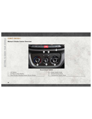 22
22 23
23 24
24 25
25 26
26 27
27 28
28 29
29 30
30 31
31 32
32 33
33 34
34 35
35 36
36 37
37 38
38 39
39 40
40 41
41 42
42 43
43 44
44 45
45 46
46 47
47 48
48 49
49 50
50 51
51 52
52 53
53 54
54 55
55 56
56 57
57 58
58 59
59 60
60 61
61 62
62 63
63 64
64 65
65 66
66 67
67 68
68 69
69 70
70 71
71 72
72 73
73 74
74 75
75 76
76 77
77 78
78 79
79 80
80 81
81 82
82 83
83 84
84 85
85 86
86 87
87 88
88 89
89 90
90 91
91 92
92 93
93 94
94 95
95 96
96 97
97 98
98 99
99 100
100 101
101 102
102 103
103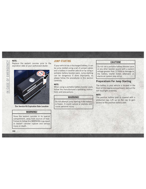 104
104 105
105 106
106 107
107 108
108 109
109 110
110 111
111 112
112 113
113 114
114 115
115 116
116 117
117 118
118 119
119 120
120 121
121 122
122 123
123 124
124 125
125 126
126 127
127 128
128 129
129 130
130 131
131 132
132 133
133 134
134 135
135 136
136 137
137 138
138 139
139 140
140 141
141 142
142 143
143 144
144 145
145 146
146 147
147 148
148 149
149 150
150 151
151 152
152 153
153 154
154 155
155 156
156 157
157 158
158 159
159 160
160 161
161 162
162 163
163 164
164 165
165 166
166 167
167 168
168 169
169 170
170 171
171 172
172 173
173 174
174 175
175 176
176 177
177 178
178 179
179