Page 297 of 318

In addition to the load-bearing index, load rat-
ing:may be imprinted after the letters that
identify speed rating on the sidewall of the tire
(
Ypage 293).
RIf no spec")
Load index
Load index (example)
In addition to the load-bearing index, load rat-
ing:may be imprinted after the letters that
identify speed rating on the sidewall of the tire
(
Ypage 293).
RIf no specification is given: no text (as in the
example above), represents a standard load
(SL) tire
RRF or Reinforced: represents a reinforced tire.
Alternatively, depending on the manufac-
turer, the designation XL (Extra Load) can be
used.
RLight Load: represents a light load tire
RC, D, E: represents a load range that depends
on the maximum load that the tire can carry at
a certain pressure
iTire data is vehicle-specific and may deviate
from the data in the example.
Maximum tire load
Example: maximum tire load
Maximum tire load :is the maximum permis-
sible weight for which the tire is approved.
Do not overload the tires by exceeding the
specified load limit. The maximum permissible load can be found on the vehicle's Tire and
Loading Information placard on the B-pillar on
the driver's side (
Ypage 290).
iThe actual values for tires are specific to
each vehicle and may deviate from the values
in the illustration.
DOT, Tire Identification Number (TIN)
U.S. tire regulations stipulate that every tire
manufacturer or retreader must imprint a TIN in
or on the sidewall of each tire produced.
The TIN is a unique identification number. The
TIN enables the tire manufacturers or retreaders
to inform purchasers of recalls and other safety-
relevant matters. It makes it possible for the
purchaser to easily identify the affected tires.
The TIN is made up of manufacturer identifica-
tion code ;, tire size =, tire type code ?and
manufacturing date A.
DOT (Department of Transportation): tire
symbol :indicates that the tire complies with
the requirements of the U.S. Department of
Transportation.
Manufacturer identification code: manufac-
turer identification code ;provides details on
the tire manufacturer. New tires have a code
with two symbols. Retreaded tires have a code
with four symbols.
Further information about retreaded tires
(
Ypage 279).
Tire size: identifier=describes the tire size.
Tire type code: tire type code?can be used by
the manufacturer as a code to describe specific
characteristics of the tire.
Date of manufacture: date of manufactureA
provides information about the age of a tire. The first and second positions represent the week of
manufacture, starting with "01" for the first cal-
endar week. Positions three and four represent
What you should know about wheels and tires295
Wheels and tires
Z
Page 298 of 318

the year of manufacture. For example, a tire that
is marked with "3208" was manufactured in
week 32 in 2008.
iTire data is vehicle-specific and may deviate
from the data in the example.
Tire characteristics
This information describes the type of tire cord
and the number of layers in sidewall :and
under tire tread ;.
iTire data is vehicle-specific and may deviate
from the data in the example.
Definitions for tires and loading
Tire structure and characteristics
Describes the number of layers or the number of
rubber-coated belts in the tire tread and the tire
wall. These consist of steel, nylon, polyester,
and other materials.
Bar
Metric unit for tire pressure. 14.5038 pounds
per square inch (psi) and 100 kilopascals (kPa)
are the equivalent of 1 bar.
DOT (Department of Transportation)
DOT marked tires fulfill the requirements of the
United States Department of Transportation.
Average weight of vehicle occupants
The number of occupants for which the vehicle
is designed multiplied by 68 kilograms (150 lbs).
Uniform Tire Quality Grading Standards
A uniform standard to grade the quality of tires
with regard to tread quality, traction and tem-
perature characteristics. The quality grading
assessment is made by the manufacturer fol-
lowing specifications from the U.S government.
The quality grade of a tire is imprinted on the
sidewall of the tire.
Recommended tire pressure
The recommended tire pressures are the pres-
sures specified for the tires mounted on the
vehicle at the factory.
The tire and load information table
1contains the
recommended tire pressures for cold tires, the
maximum permissible load and the maximu
m
permissible vehicle speed.
The tire pressure table contains the recommen-
ded tire pressure for cold tires under various
operating conditions, i.e. loading and/or speed
of the vehicle.
Increased vehicle weight due to optional
equipment
The combined weight of all standard and
optional equipment available for the vehicle,
regardless of whether it is actually installed on
the vehicle or not.
Wheel rim
The part of the wheel on which the tire is moun-
ted.
GAWR (Gross Axle Weight Rating)
GAWR is the maximum gross axle weight rating.
The actual load on an axle must never exceed
the gross axle weight rating. You can find the
maximum gross axle weight rating on the B-pillar
on the driver's side (
Ypage 305).
Speed index
The speed index is part of the tire identification. It specifies the speed range for which the tire is
approved.
GTW (Gross Trailer Weight)
GTW is the total of weight of a trailer and the
weight of the load, accessories etc. on the
trailer.
1Only for vehicles with a gross weight of less than 10,000 lbs (4536 kg).
296What you should know about wheels and tires
Wheels and tires
Page 299 of 318

The gross vehicle weight includes the weight of
the vehicle including fuel, tools, spare wheel,
accessories installed, occupants, luggage and
the drawbar noseweight if appli")
GVW (Gross Vehicle Weight)
The gross vehicle weight includes the weight of
the vehicle including fuel, tools, spare wheel,
accessories installed, occupants, luggage and
the drawbar noseweight if applicable. The gross
vehicle weight must never exceed the permissi-
ble gross weight (GVWR) specified on the
B-pillar on the driver's side (
Ypage 305).
GVWR (Gross Vehicle Weight Rating)
The GVWR is the maximum permitted gross
weight of the fully laden vehicle (weight of the
vehicle including all accessories, occupants,
fuel, luggage and the drawbar noseweight if
applicable). The permissible gross weight is
specified on the vehicle identification plate on
the B-pillar on the driver's side (
Ypage 305).
Maximum weight of the laden vehicle
The maximum weight is the sum of:
Rthe curb weight of the vehicle
Rthe weight of the accessories
Rthe load limit
Rthe weight of the factory installed optional
equipment
Kilopascal (kPa)
Metric unit for tire pressure. 6.9 kPa are the
equivalent of 1 psi. Another tire pressure unit is
bar. 100 kilopascals (kPa) are the equivalent of
1 bar.
Load index
In addition to the load bearing index, a load
index can be stamped onto the sidewall of the
tire. It specifies the load-bearing capacity of the
tire more precisely.
Curb weight
The weight of a vehicle with standard equipment
including the maximum filling capacity of fuel,
oil, and coolant. It also includes the air-condi-
tioning system and optional equipment if these
are installed on the vehicle, but does not include
passengers or luggage.
Maximum tire load
The maximum tire load in kilograms or pounds is
the maximum weight for which a tire is
approved.
Maximum permissible tire pressure
Maximum permissible tire pressure for one tire.
Maximum load on one tire
Maximum load on one tire. This is calculated by
dividing the maximum axle load of one axle by
two.
PSI (Pounds per square inch)
Standard unit of measurement for tire pressure.
Aspect ratio
Relationship between tire height and width in
percent.
Tire pressure
Pressure inside the tire applying an outward
force to every square inch of the tire's surface.
Tire pressure is specified in pounds per square
inch (psi), in kilopascal (kPa) or in bar. Tire pres-
sure should only be corrected when the tires are
cold.
Cold tire pressure
The tires are cold:
Rif the vehicle has been parked for at least
three hours without direct sunlight on the
tires, and
Rif the vehicle has not been driven further than
1 mile (1.6 km)
Tire tread
The part of the tire that comes into contact with
the road.
Tire bead
The tire bead ensures that the tire sits securely
on the wheel. There are several steel wires in the bead to prevent the tire from coming loose from
the wheel rim.
Sidewall
The part of the tire between the tread and the
tire bead.
Weight of optional extras
The combined weight of those optional extras
that weigh more than the replaced standard
parts and more than 2.3 kg (5 lbs). These
optional extras, such as high-performance
brakes, a roof rack or a high-performance bat-
tery, are not included in the curb weight and theweight of the accessories.
What you should know about wheels and tires297
Wheels and tires
Z
Page 300 of 318

A unique identification number which can be
used by a tire manufacturer to identify tires, for
example for a product recall, and thus identify
the purchasers. The TIN")
TIN (Tire Identification Number)
A unique identification number which can be
used by a tire manufacturer to identify tires, for
example for a product recall, and thus identify
the purchasers. The TIN is composed of the
manufacturer identification code, tire size, tire
model code and manufacturing date.
Load bearing index
The load bearing index (also load index) is a code
that contains the maximum load bearing capa-
city of a tire.
Traction
Traction is the result of friction between the tires
and the road surface.
TWR (permissible trailer drawbar load)
The TWR is the maximum permissible weight
that may act on the ball coupling of the trailer
tow hitch.
Wear indicator
Narrow bars (tread wear bars) that are distrib-
uted over the tire tread. If the tire tread is level
with the bars, the wear limit of áin (1.6 mm)
has been reached.
Distribution of the vehicle occupants
The distribution of vehicle occupants over des-
ignated seat positions in a vehicle.
Maximum permissible payload weight
Nominal load and goods/luggage load plus
68 kg (150 lb s)multiplied by the number of
seats in the vehicle.
Changing wheels
Rotating the wheels
GWARNING
Interchanging the front and rear wheels may
severely impair the driving characteristics if
the wheels or tires have different dimensions. The wheel brakes or suspension components
may also be damaged. There is a risk of acci-
dent.
Rotate front and rear wheels only if the wheels and tires are of the same dimensions.
!On vehicles equipped with a tire pressure
monitor, electronic components are located
in the wheel.
Tire-mounting tools should not be used near
the valve. This could damage the electronic
components.
Only have tires changed at a qualified spe-
cialist workshop.
Always observe the instructions and safety
notes under "Mounting a wheel" (
Ypage 299).
The wear patterns on the front and rear tires
differ, depending on the operating conditions.
Rotate the wheels before a clear wear pattern
has formed on the tires. Front tires typically
wear more on the shoulders and the rear tires in the center.
If your vehicle's tire configuration allows, you
can rotate the tires according to the intervals in
the tire manufacturer's warranty book in your
vehicle documents. If no warranty book is avail-
able, the tires should be rotated every 3,000 to
6,000 miles (5,000 to 10,000 km) or earlier if
tire wear requires. Do not change the direction
of rotation.
Clean the contact surfaces of the wheel and the
brake disc thoroughly every time a wheel is rota-
ted. Avoid oily or greasy cleaning agents.
Check the tire pressure and reactivate the tire
pressure monitor if necessary.
Direction of rotation
Tires with a specified direction of rotation have
additional benefits, e.g. if there is a risk of hydro-
planing. You will only gain these benefits if the
correct direction of rotation is observed.
An arrow on the sidewall of the tire indicates its
correct direction of rotation.
You may mount a spare wheel against the direc-tion of rotation. Observe the time restriction on
use as well as the speed limitation specified on
the spare wheel.
Storing wheels
Store wheels that are not being used in a cool,
dry and preferably dark place. Protect the tires
from contact with oil, grease and fuel.
298Changing wheels
Wheels and tires
Page 301 of 318

Mounting a wheel
Vehicle preparation
XStop the vehicle as far away as possible from
traffic and on a level, firm and non-slip sur-
face.
XIf your vehicle poses a risk to approaching
traffic, switch on the hazard warning lamps.
XApply the parking brake.
XTurn the front wheels to the straight-ahead
position.
XShift the transmission to position P.
XSwitch off the engine.
XPassengers should leave the vehicle. Make
sure that the passengers are not endangered
as they do so.
XMake sure that no one is near the danger area
while the wheel is being changed. Anyone
who is not directly assisting in the wheel
change should, for example, stand behind the
barrier.
XPlace the warning triangle or warning lamp at
a suitable distance.
Observe the legal requirements on the cor-
rect use of the warning triangle or warning
lamp for the country in which you are cur-
rently driving
XSecure the vehicle to prevent it from rolling
away.
Observe the safety notes on parking under
"Driving and parking" (
Ypage 135)
XOn level terrain: place chocks or other suit-
able objects under the front and rear of the
wheel that is diagonally opposite the wheel to
be changed.
XOn slight inclines: place chocks or other
suitable objects under the wheels on the front and rear axles opposite the wheel to be
changed.
XIf included in the vehicle equipment, take the
tire-changing tool kit out of the vehicle tool kit
(
Ypage 272).
Apart from some country-specific variants,
vehicles are not equipped with tire-changing
tools. Some tools for changing a wheel are
specific to the vehicle. Consult a qualified
specialist workshop for more information on
which tools are required to perform a wheel
change on your vehicle.
XIf included in the vehicle equipment, remove
the spare wheel from the spare wheel bracket (
Ypage 303). Observe the safety notes listed
under "Spare wheel" (Ypage 303).
XCarefully remove the hub caps.
XUsing lug wrench :, loosen the wheel bolts
on the wheel to be changed counter-clock-
wise by about one full turn. Do not remove the
wheel bolts.
Raising the vehicle
GWARNING
If you do not position the jack correctly at the
appropriate jacking point of the vehicle, the
jack could tip over with the vehicle raised.
There is a risk of injury.
Only position the jack at the appropriate jack-
ing point of the vehicle. The base of the jack
must be positioned vertically, directly under
the jacking point of the vehicle.
GWARNING
On uphill and downhill slopes, the jack could
tip over with the vehicle raised. There is a risk
of injury.
Do not change wheels on uphill or downhill
gradients. Notify a qualified specialist work-
shop.
!Only position the jack on the jacking points
intended for this purpose. You could other-
wise damage the vehicle.
Observe the following when raising the vehicle:
RTo raise the vehicle, only use the vehicle-spe-
cific jack that has been tested and approved
by Mercedes-Benz. If the jack is used incor-
Changing wheels299
Wheels and tires
Z
Page 302 of 318

rectly, it could tip over while the vehicle is
raised.
RThe vehicle's jack is intended only to raise the
vehicle for a short time when changing a
wheel. It is not suited for performing mainte-
nance work under the vehicle.
RAvoid changing the wheel on uphill and down-
hill slopes.
RBefore raising the vehicle, secure it from roll-
ing away by applying the parking brake and
inserting wheel chocks. Never disengage the
parking brake while the vehicle is raised.
RThe jack must be placed on a firm, flat and
non-slip surface. On a loose surface, a large,
load-bearing underlay must be used. On a
slippery surface, a non-slip underlay must be
used, e.g. rubber mats.
RMake sure that the distance between the
underside of the tires and the ground does not
exceed 1.2 in(3 cm).
RNever place your hands or feet under the
raised vehicle.
RNever lie under the raised vehicle.
RNever start the engine when the vehicle is
raised.
RNever open or close a door or the tailgate/
door when the vehicle is raised.
RMake sure that no persons are present in the
vehicle when the vehicle is raised.
Jacking points :(rubber stoppers) are located
just behind the front wheel arches and just in
front of the rear wheel arches.
XPlace jack ;beneath corresponding jacking
points :.
XTurn handwheel =until jack plate ;sits
securely on jacking point :.
XMake sure the base of jack ;is positioned
vertically beneath jacking point :.
XAssemble adapter?and ratchet Afrom the
vehicle tool kit.
XPlace adapter ?and ratchet Aon the hex-
agon nut of jack ;so that the lettering AB/
DOWN is visible.
XTurn ratchet Ain the AUF/UP direction until
the tire is a maximum of 3 cm off the ground.
When doing so, jack ;may move to one of
the side support surfaces.
Removing a wheel
!Do not place wheel bolts in sand or on a dirty
surface. The bolt and wheel hub threads could
otherwise be damaged when you screw them
in.
XUnscrew the wheel bolts.
XRemove the wheel.
Mounting a new wheel
GWARNING
Oiled or greased wheel bolts or damaged
wheel bolts/hub threads can cause the wheel bolts to come loose. As a result, you could
lose a wheel while driving. There is a risk of
accident.
Never oil or grease wheel bolts. In the event of
damage to the threads, contact a qualified
specialist workshop immediately. Have the
damaged wheel bolts or hub threads
replaced/renewed. Do not continue driving.
GWARNING
If you tighten the wheel bolts or wheel nuts
when the vehicle is raised, the jack could tip
over. There is a risk of injury.
Only tighten the wheel bolts or wheel nuts
when the vehicle is on the ground.
Always observe the instructions and safety
notes on "Changing a wheel" (
Ypage 298).
300Changing wheels
Wheels and tires
Page 303 of 318

Only use wheel bolts that have been designed
for the wheel and the vehicle. For safety rea-
sons, Mercedes-Benz recommends that you
only use wheel bolts which have been approved
for Mercedes-Benz vehicles and the respective
wheel.
!On vehicles equipped with a tire pressure
monitor, electronic components are located
in the wheel.
Tire-mounting tools should not be used near
the valve. This could damage the electronic
components.
Only have tires changed at a qualified spe-
cialist workshop.
XClean the wheel and wheel hub contact sur-
faces.
XSlide the new wheel onto the wheel hub and
push it on.
XScrew in the wheel bolts and tighten them
lightly.
Lowering the vehicle
GWARNING
The wheels could work loose if the wheel nuts and bolts are not tightened to the specified
tightening torque. There is a risk of accident.
Have the tightening torque immediately
checked at a qualified specialist workshop
after a wheel is changed.
:—AWheel bolts
XPlace the adapter and the ratchet on the hex-
agon head nut of the jack such that the let-
tering AB/DOWN is visible.
XTurn the ratchet in the AB/DOWNdirection
until the vehicle is once again standing firmly
on the ground.
XPut the jack aside.
XTighten the wheel bolts evenly in a crosswise
pattern in the sequence indicated (: toA).
Tighten the wheel bolts to the following tight-
ening torques:
RSteel wheel 147 lb-ft(200 Nm)
RAlloy wheel 133 lb-ft(180 Nm)
XTurn the jack back to its out-of-use position.
XStow the jack and the rest of the tire-change
tool kit in the vehicle again.
XWheel with hub cap: position the opening for
the tire valve in the hub cap over the tire valve.
XPush the edge of the hub cap with both hands
against the wheel until it clicks into place.
Make sure the hub cap retaining catches
engage on the steel wheel.
XIf included in the vehicle equipment, secure
the faulty wheel in the spare wheel bracket
(
Ypage 303). Otherwise, transport the faulty
wheel in the cargo compartment.
XCheck the tire pressure of the newly mounted
wheel and adjust it if necessary.
Observe the recommended tire pressure
(
Ypage 282).
Vehicles with the tire pressure monitor sys-
tem: all mounted wheels must be equipped
with functioning sensors.
XRetighten the wheel bolts or wheel nuts to the
specified tightening torque after the vehicle
has been driven for 30 miles (50 km).
Changing wheels301
Wheels and tires
Z
Page 304 of 318
. Observe the
specified tig")
When using a wheel/spare wheel with a new or
newly painted wheel rim, have the wheel bolts/
nuts retightened again after approximately 600
to 3,000 miles (1,000 to 5,000 km). Observe the
specified tightening torque.
Wheel and tire combination
General notes
!
Retreaded tires are neither tested nor rec-
ommended by Mercedes-Benz, since previ-
ous damage cannot always be detected on
retreaded tires. As a result, Mercedes-Benz
cannot guarantee vehicle safety if retreaded
tires are mounted. Do not mount used tires if you have no information about their previous
usage.
!For safety reasons, Mercedes-Benz recom-
mends that you only use tires, wheels and
accessories which have been specially
approved by Mercedes-Benz for your vehicle.
These tires have been specially adapted for
use with the driving safety systems, such as
ABS or ESP
®.
Only use tires, wheels or accessories tested
and approved by Mercedes-Benz. Certain
characteristics, e.g. handling, vehicle noise
emissions or fuel consumption, may other-
wise be adversely affected. In addition, when
driving with a load, tire dimension variations
could cause the tires to come into contact
with the bodywork and axle components. This could result in damage to the tires or the vehi-
cle.
Mercedes-Benz accepts no liability for dam-
age resulting from the use of tires, wheels or
accessories other than those tested and
approved.
Further information on wheels, tires and
approved combinations can be obtained from
any qualified specialist workshop.
!Large wheels: the lower the section width
for a certain wheel size, the lower the ride
comfort is on poor road surfaces. Roll comfort and suspension comfort are reduced and the
risk of damage to the wheels and tires as a
result of driving over obstacles increases.
You will find a table with the recommended tire
pressures for various vehicle loads on the inside
of your vehicle's fuel filler flap or under "Tire
pressure tables" (
Ypage 290). You can find fur-
ther information under "Tire pressure"
(
Ypage 282).
Check tire pressures regularly and only when
the tires are cold.
Notes on the vehicle equipment – always equip
the vehicle:
Rwith tires of the same size across an axle
(left/right)
Rwith the same type of tires on all wheels at a
given time (summer tires, winter tires)
iNot all wheel/tire combinations can be
installed at the factory in all countries.
Tires
R 17
TiresSteel wheels
225/55 R17 RF (XL) 101V6.5 J x 17 H2 ET 50
225/55 R17 RF (XL) 101H6.5 J x 17 H2 ET 50
R 17
TiresAlloy wheels
225/55 R17 RF (XL) 101V7 J x 17 H2 ET 51
225/55 R17 RF (XL) 101H7 J x 17 H2 ET 51
302Wheel and tire combination
Wheels and tires
 1
1 2
2 3
3 4
4 5
5 6
6 7
7 8
8 9
9 10
10 11
11 12
12 13
13 14
14 15
15 16
16 17
17 18
18 19
19 20
20 21
21 22
22 23
23 24
24 25
25 26
26 27
27 28
28 29
29 30
30 31
31 32
32 33
33 34
34 35
35 36
36 37
37 38
38 39
39 40
40 41
41 42
42 43
43 44
44 45
45 46
46 47
47 48
48 49
49 50
50 51
51 52
52 53
53 54
54 55
55 56
56 57
57 58
58 59
59 60
60 61
61 62
62 63
63 64
64 65
65 66
66 67
67 68
68 69
69 70
70 71
71 72
72 73
73 74
74 75
75 76
76 77
77 78
78 79
79 80
80 81
81 82
82 83
83 84
84 85
85 86
86 87
87 88
88 89
89 90
90 91
91 92
92 93
93 94
94 95
95 96
96 97
97 98
98 99
99 100
100 101
101 102
102 103
103 104
104 105
105 106
106 107
107 108
108 109
109 110
110 111
111 112
112 113
113 114
114 115
115 116
116 117
117 118
118 119
119 120
120 121
121 122
122 123
123 124
124 125
125 126
126 127
127 128
128 129
129 130
130 131
131 132
132 133
133 134
134 135
135 136
136 137
137 138
138 139
139 140
140 141
141 142
142 143
143 144
144 145
145 146
146 147
147 148
148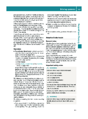 149
149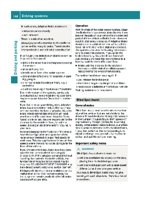 150
150 151
151 152
152 153
153 154
154 155
155 156
156 157
157 158
158 159
159 160
160 161
161 162
162 163
163 164
164 165
165 166
166 167
167 168
168 169
169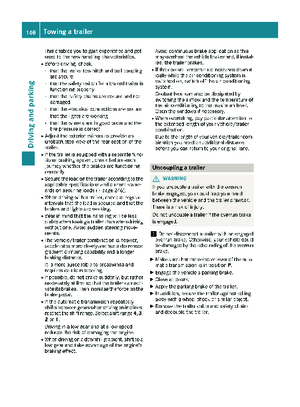 170
170 171
171 172
172 173
173 174
174 175
175 176
176 177
177 178
178 179
179 180
180 181
181 182
182 183
183 184
184 185
185 186
186 187
187 188
188 189
189 190
190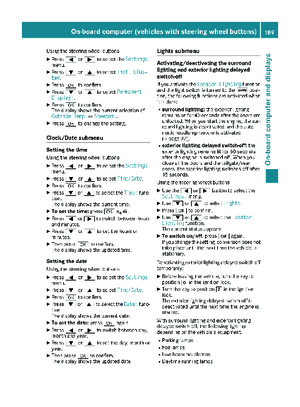 191
191 192
192 193
193 194
194 195
195 196
196 197
197 198
198 199
199 200
200 201
201 202
202 203
203 204
204 205
205 206
206 207
207 208
208 209
209 210
210 211
211 212
212 213
213 214
214 215
215 216
216 217
217 218
218 219
219 220
220 221
221 222
222 223
223 224
224 225
225 226
226 227
227 228
228 229
229 230
230 231
231 232
232 233
233 234
234 235
235 236
236 237
237 238
238 239
239 240
240 241
241 242
242 243
243 244
244 245
245 246
246 247
247 248
248 249
249 250
250 251
251 252
252 253
253 254
254 255
255 256
256 257
257 258
258 259
259 260
260 261
261 262
262 263
263 264
264 265
265 266
266 267
267 268
268 269
269 270
270 271
271 272
272 273
273 274
274 275
275 276
276 277
277 278
278 279
279 280
280 281
281 282
282 283
283 284
284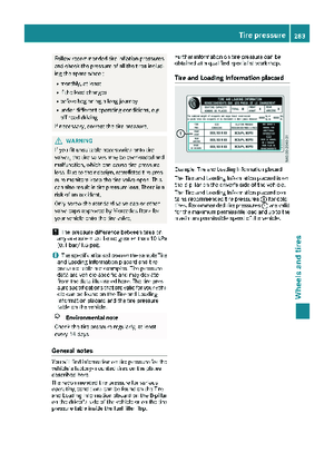 285
285 286
286 287
287 288
288 289
289 290
290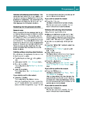 291
291 292
292 293
293 294
294 295
295 296
296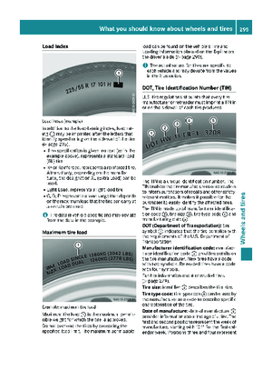 297
297 298
298 299
299 300
300 301
301 302
302 303
303 304
304 305
305 306
306 307
307 308
308 309
309 310
310 311
311 312
312 313
313 314
314 315
315 316
316 317
317