2018 MERCEDES-BENZ G-CLASS tow
[x] Cancel search: towPage 157 of 294
This also applies if you have activated cruise
control or the speed limiter.
XIf necessary, shift the transfer case toLOW
RANGE (Ypage 149).
This will use the braking effect of the engine,
so that less braking will be required to main-
tain the speed. This relieves the load on the
brake system and prevents the brakes from
overheating and wearing too quickly. If you
need additional braking, depress the brake
pedal repeatedly rather than continuously.
The maximum permissible speed for vehicle/
trailer combinations depends on the type of
trailer. Before beginning the journey, check the
trailer's documents to see what the maximum
permitted speed is. Observe the maximum per-
missible speed in the relevant country.
For certain Mercedes-Benz vehicles, the maxi-
mum permissible rear axle load is increased
when towing a trailer. See the "Technical data"
section to find out whether this applies to your
vehicle (
Ypage 291). In the event of increased
rear axle load, the car/trailer combination may
not exceed a maximum speed of 60 mph
(100 km/h) for reasons concerning the operat-
ing permit. This also applies in countries in
which the maximum permissible speed for car/ trailer combinations is greater than 60 mph
(100 km/h).
When towing a trailer, your vehicle's handling
characteristics will be different in comparison to
when driving without a trailer and it will con-
sume more fuel.
Driving tips
RMaintain a greater distance from the vehicle
in front than when driving without a trailer.
RAvoid braking abruptly. If possible, brake gen-tly at first to allow the trailer to run on. Then,
increase the braking force rapidly.
RThe values given for gradient-climbing capa-
bilities from a standstill refer to sea level.
When driving in mountainous areas, note that
the power output of the engine and, conse-
quently, the vehicle's gradient-climbing capa-
bility, decreases with increasing altitude.
If the trailer swings from side to side:
XDo not accelerate.
XDo not counter-steer.
XBrake if necessary.
Assembling the ball coupling
GWARNING
The ball coupling can be damaged if the nut on
the ball coupling is tightened using the incor-
rect torque. As a result, the trailer may
detach. There is a risk of an accident.
Immediately after installing, have the tighten-
ing torque checked at a qualified specialist
workshop.
!Mercedes-Benz recommends that you only
use ball couplings tested and approved for
use on Mercedes-Benz vehicles. This helps to avoid damage to the vehicle.
Observe the manufacturer's installation
instructions if you use a ball coupling other
than the one supplied.
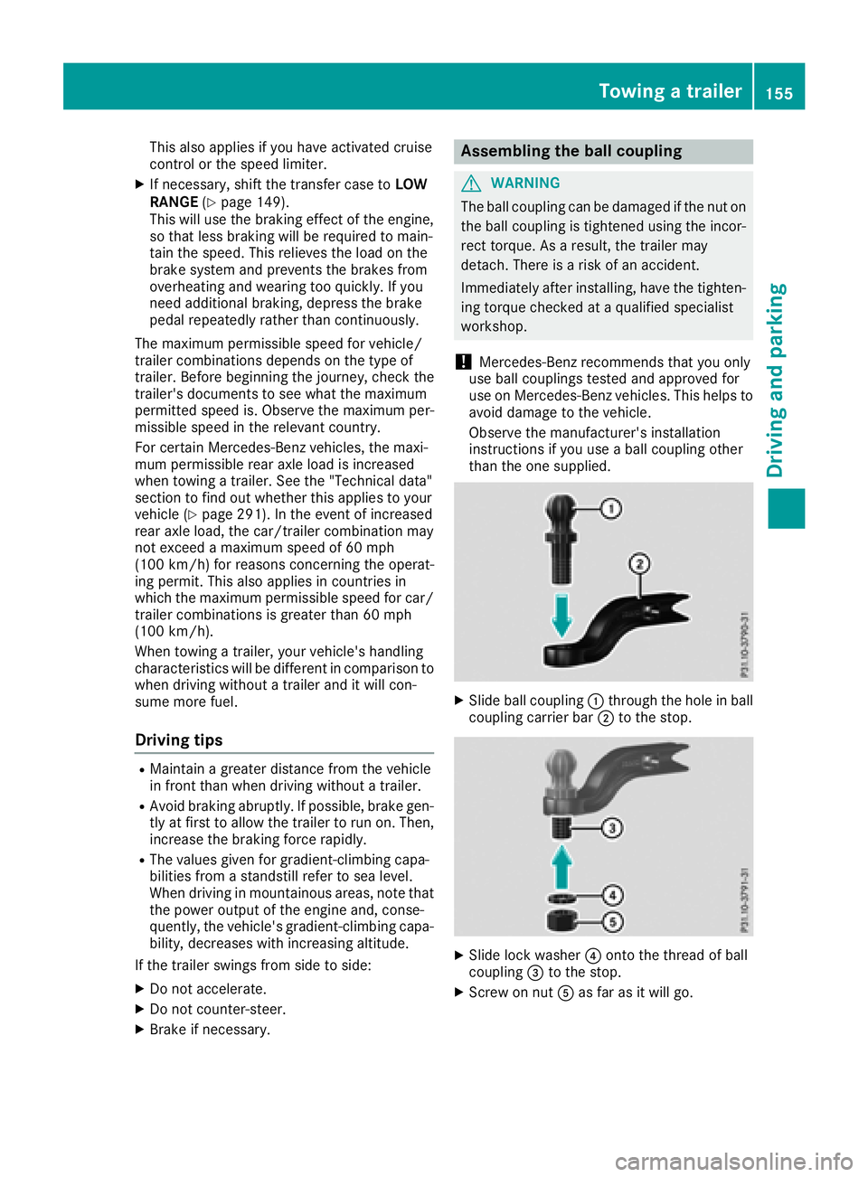
XSlide ball coupling :through the hole in ball
coupling carrier bar ;to the stop.
XSlide lock washer ?onto the thread of ball
coupling =to the stop.
XScrew on nut Aas far as it will go.
Towing a trailer155
Driving and parking
Z
Page 158 of 294
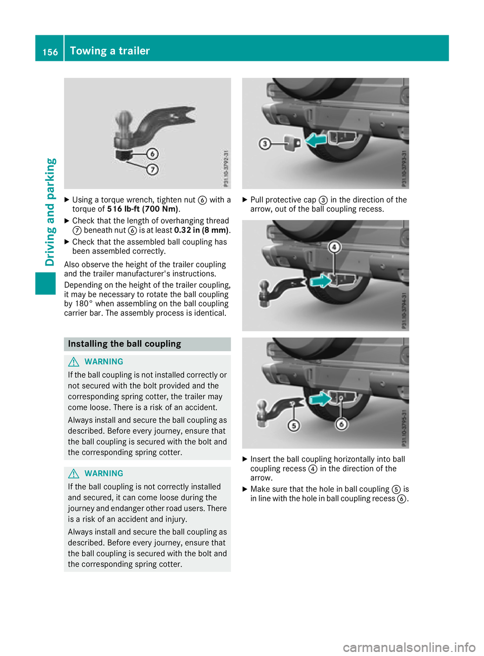
XUsing a torque wrench, tighten nutBwith a
torque of 516 lb-ft (700 Nm) .
XCheck that the length of overhanging thread
Cbeneath nut Bis at least 0.32 in (8 mm) .
XCheck that the assembled ball coupling has
been assembled correctly.
Also observe the height of the trailer coupling
and the trailer manufacturer's instructions.
Depending on the height of the trailer coupling,
it may be necessary to rotate the ball coupling
by 180° when assembling on the ball coupling
carrier bar. The assembly process is identical.
Installing the ball coupling
GWARNING
If the ball coupling is not installed correctly or not secured with the bolt provided and the
corresponding spring cotter, the trailer may
come loose. There is a risk of an accident.
Always install and secure the ball coupling as
described. Before every journey, ensure that
the ball coupling is secured with the bolt and
the corresponding spring cotter.
GWARNING
If the ball coupling is not correctly installed
and secured, it can come loose during the
journey and endanger other road users. There is a risk of an accident and injury.
Always install and secure the ball coupling as
described. Before every journey, ensure that
the ball coupling is secured with the bolt and
the corresponding spring cotter.
XPull protective cap =in the direction of the
arrow, out of the ball coupling recess.
XInsert the ball coupling horizontally into ball
coupling recess ?in the direction of the
arrow.
XMake sure that the hole in ball coupling Ais
in line with the hole in ball coupling recess B.
156Towing a trailer
Driving and parking
Page 159 of 294
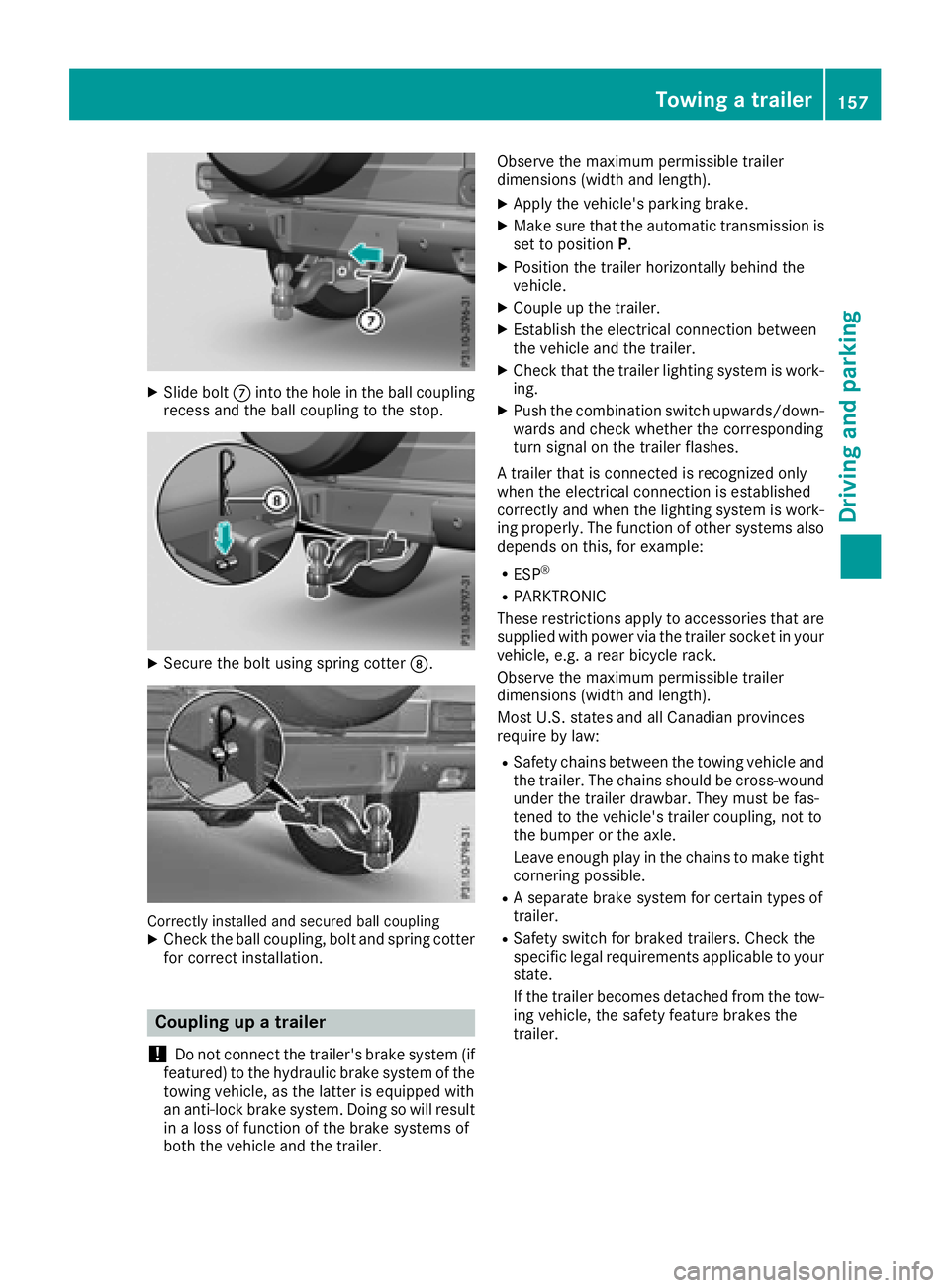
XSlide boltCinto the hole in the ball coupling
recess and the ball coupling to the stop.
XSecure the bolt using spring cotter D.
Correctly installed and secured ball couplingXCheck the ball coupling, bolt and spring cotter
for correct installation.
Coupling up a trailer
!
Do not connect the trailer's brake system (if
featured) to the hydraulic brake system of the
towing vehicle, as the latter is equipped with
an anti-lock brake system. Doing so will result
in a loss of function of the brake systems of
both the vehicle and the trailer. Observe the maximum permissible trailer
dimensions (width and length).
XApply the vehicle's parking brake.
XMake sure that the automatic transmission is
set to position
P.
XPosition the trailer horizontally behind the
vehicle.
XCouple up the trailer.
XEstablish the electrical connection between
the vehicle and the trailer.
XCheck that the trailer lighting system is work-
ing.
XPush the combination switch upwards/down-
wards and check whether the corresponding
turn signal on the trailer flashes.
A trailer that is connected is recognized only
when the electrical connection is established
correctly and when the lighting system is work-
ing properly. The function of other systems also
depends on this, for example:
RESP®
RPARKTRONIC
These restrictions apply to accessories that are
supplied with power via the trailer socket in your
vehicle, e.g. a rear bicycle rack.
Observe the maximum permissible trailer
dimensions (width and length).
Most U.S. states and all Canadian provinces
require by law
:
RSafety chains between the towing vehicle and
the trailer. The chains should be cross-wound
under the trailer drawbar. They must be fas-
tened to the vehicle's trailer coupling, not to
the bumper or the axle.
Leave enough play in the chains to make tight
cornering possible.
RA separate brake system for certain types of
trailer.
RSafety switch for braked trailers. Check the
specific legal requirements applicable to your
state.
If the trailer becomes detached from the tow-
ing vehicle, the safety feature brakes the
trailer.
Towing a trailer157
Driving and parking
Z
Page 160 of 294

Towing a trailer
There are several legal requirements for towing
a trailer, e.g. the maximum permissible speed.
Make sure that your car/trailer combination
complies with the local regulations:
Rin your place of residence
Rat your destination
The police and local authorities can provide reli- able information.
In order to accumulate driving experience and
accustom yourself to the new handling charac-
teristics, practice the following at a location
where there is no traffic:
RCornering
RStopping
RBacking up
Before driving, check the following:
RTrailer tow hitch
RSafety switch for braked trailers
RSafety chains
RElectrical connections
RLighting system
RWheels and tires
RLoad-securing measures
Adjust the exterior mirrors to provide an unob-
structed view of the rear section of the trailer.
Trailers with electronically controlled
brakes: pull away carefully in the vehicle/trailer
combination, brake manually using the brake
controller and check whether the brakes func-
tion correctly.
Check the load securing measures on a regular
basis.
When towing a trailer, your vehicle's handling
characteristics will be different in comparison
with when driving without a tra
iler.
The vehicle/trailer combination:
Ris heavier
Ris restricted in its acceleration and gradient-
climbing capability
Rhas an increased braking distance
Ris affected more by strong crosswinds
Rdemands more sensitive steering
Rhas a larger turning radius
Avoid sudden steering movements.
Avoid braking abruptly. If possible, brake gently
at first to allow the trailer to run on. Then,
increase the braking force rapidly. When overtaking, pay particular attention to the
extended length of your vehicle/trailer combi-
nation.
Due to the length of the vehicle/trailer combi-
nation, you require additional road space when
overtaking before you can change back to the
original lane.
If the automatic transmission repeatedly shifts
between gears on uphill or downhill gradients,
shift to a lower gear.
Driving in a lower gear and at a reduced speed
decreases the risk of engine damage.
Avoid constant braking. Otherwise, the vehicle
brakes and possibly also the trailer brakes may
overheat.
When driving downhill, shift to a lower gear to
utilize the engine's braking effect.
If the coolant temperature increases dramati-
cally while the air-conditioni ng s
ystem is
switched on, switch off the air-conditioning sys- tem.
Coolant heat can also be dissipated by opening
the windows and switching the ventilation
blower and the interior temperature to the high-
est level.
Decoupling a trailer
GWARNING
If you uncouple a trailer with the overrun
brake engaged, you could trap your hand
between the vehicle and the trailer drawbar.
There is a risk of injury.
Do not uncouple a trailer if the overrun brake
is engaged.
!Do not disconnect a trailer with an engaged
overrun brake. Otherwise, your vehicle could
be damaged by the rebounding of the overrun
brake.
XApply the parking brake.
XMake sure that the automatic transmission is
set to position P.
XSecure the vehicle and trailer against rolling
away.
XClose all doors, including the rear door.
XRemove the trailer cable.
XRemove the safety chains, if there are any.
XUncouple the trailer.
158Towing a trailer
Driving an d parking
Page 161 of 294
Permissible trailer and drawbar loads
Weight specifications
The gross trailer weight is calculated as the
weight of the trailer plus the weight of the load
and the trailer's equipment.
You will find permissible trailer loads under
"Technical data" (
Ypage 291).
Loading a trailer
RWhen loading the trailer, make sure that nei-
ther the permissible gross trailer weight nor
the permissible gross vehicle weight are
exceeded. The permissible gross vehicle
weight is indicated on the identification plate on the B-pillar on the driver's side of the vehi-
cle.
You can find the maximum permissible values
on the type plates of your vehicle and the
trailer. When calculating how much weight
the vehicle and trailer may carry, pay atten-
tion to the respective lowest values.
RThe trailer drawbar load on the ball coupling
must be added to the rear axle load to avoid
exceeding the permissible gross axle weight.
The permissible gross vehicle weight is indi-
cated on the identification plate on the B-pil-
lar on the driver's side of the vehicle.
Mercedes-Benz recommends a trailer load
where the trailer drawbar noseweight accounts
for 8% to 15% of the permissible gross trailer
weight.
Additional accessories, passengers and load
reduce the permissible trailer load and nose-
weight that your vehicle can tow.
Checking the vehicle and trailer weight
RHave the towing vehicle, including the driver,
passengers and load, and completely loaded
trailer weighed on a suitable weighing
machine. This will allow you to ensure that the
weights of the towing vehicle and trailer com-
ply with the maximum permissible values.
RCheck the gross axle weight rating of the front
and rear axles, the gross weight of the trailer
and trailer drawbar load.
Trailer power supply
!
You can connect accessories with a maxi-
mum power consumption of 180 W to the
permanent power supply.
You must not charge a trailer battery using the
power supply.
The trailer socket of your vehicle is equipped at
the factory with a permanent power supply.
The permanent power supply is supplied via
trailer socket pin 9.
A qualified specialist workshop can provide
more information about installing the trailer
electrics.
Trailer with 7-pin connector
General notes
Trailers with 7-pin connector: you can make a
connection to the 13-pin connector on the ball
coupling using an adapter plug or, if necessary,
an adapter cable. Both can be obtained in a
qualified specialist workshop.
Installing the adapter
!Make sure that there is enough slack in the
cable for cornering so that the cable cannot
become detached.
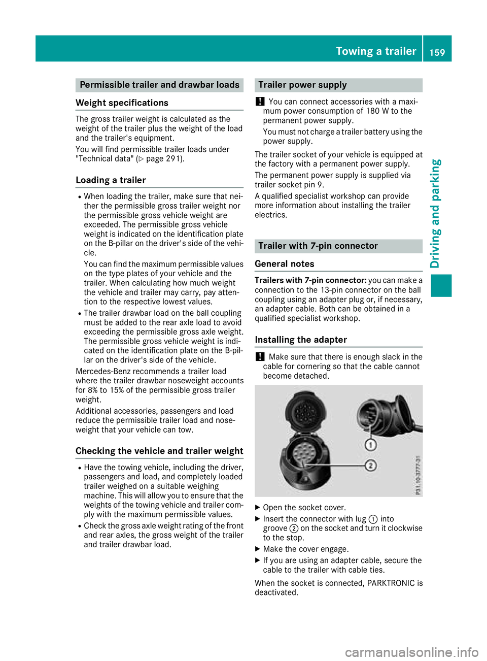
XOpen the socket cover.
XInsert the connector with lug :into
groove ;on the socket and turn it clockwise
to the stop.
XMake the cover engage.
XIf you are using an adapter cable, secure the
cable to the trailer with cable ties.
When the socket is connected, PARKTRONIC is
deactivated.
Towing a trailer159
Driving and parking
Z
Page 166 of 294
Navigation system menu
Displaying navigation instructions
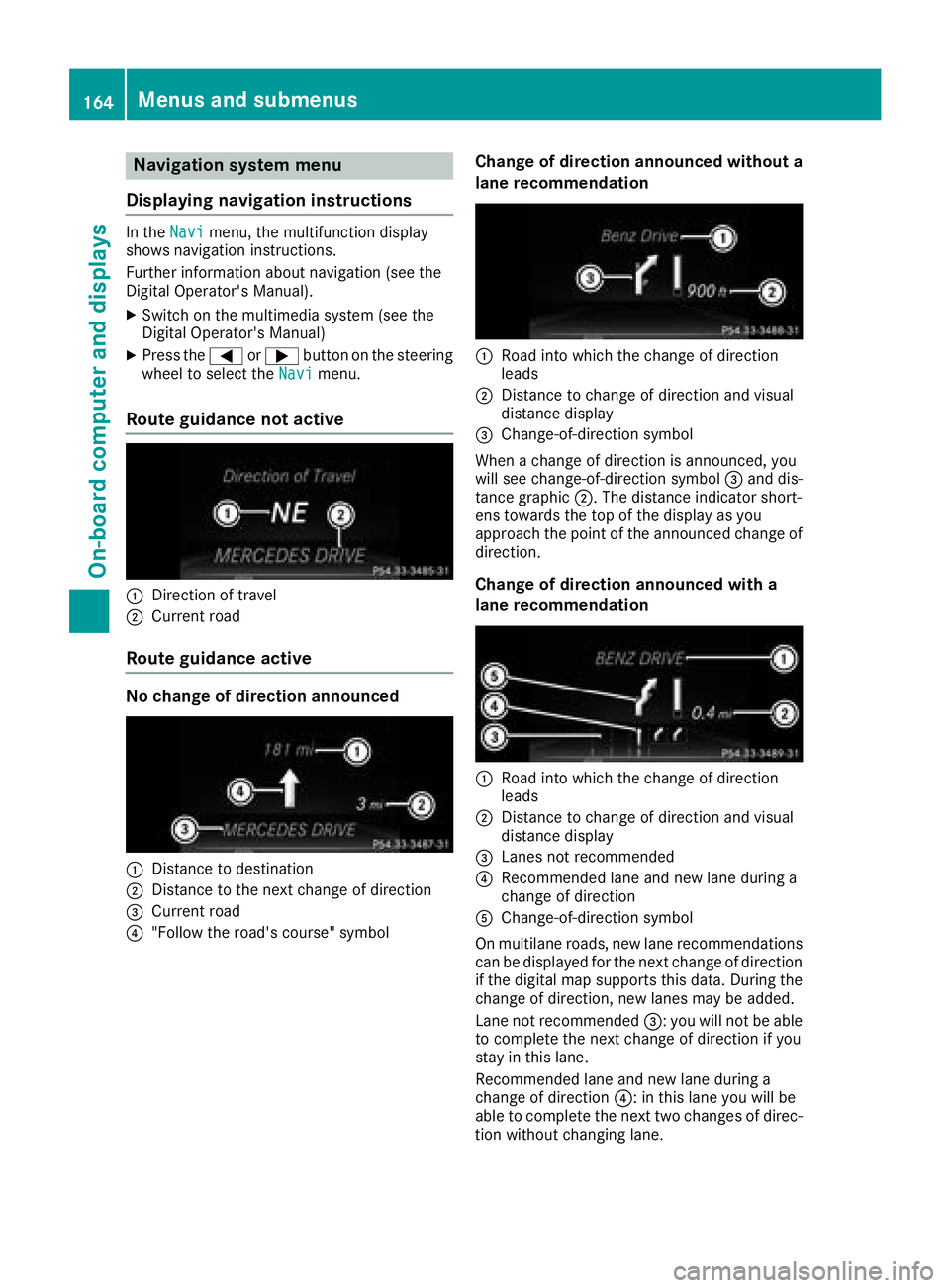
In the Navimenu, the multifunction display
shows navigation instructions.
Further information about navigation (see the
Digital Operator's Manual).
XSwitch on the multimedia system (see the
Digital Operator's Manual)
XPress the =or; button on the steering
wheel to select the Navimenu.
Route guidance not active
:Direction of travel
;Current road
Route guidance active
No change of direction announced
:Distance to destination
;Distance to the next change of direction
=Current road
?"Follow the road's course" symbol
Change of direction announced without a
lane recommendation
:Road into which the change of direction
leads
;Distance to change of direction and visual
distance display
=Change-of-direction symbol
When a change of direction is announced, you
will see change-of-direction symbol =and dis-
tance graphic ;. The distance indicator short-
ens towards the top of the display as you
approach the point of the announced change of
direction.
Change of direction announced with a
lane recommendation
:Road into which the change of direction
leads
;Distance to change of direction and visual
distance display
=Lanes not recommended
?Recommended lane and new lane during a
change of direction
AChange-of-direction symbol
On multilane roads, new lane recommendations can be displayed for the next change of direction
if the digital map supports this data. During the
change of direction, new lanes may be added.
Lane not recommended =: you will not be able
to complete the next change of direction if you
stay in this lane.
Recommended lane and new lane during a
change of direction ?: in this lane you will be
able to complete the next two changes of direc-
tion without changing lane.
164Menus and submenus
On-board computer and displays
Page 187 of 294

Display messagesPossible causes/consequences andMSolutions
Blind SpotAssistCurrently Unavaila‐ble
See Operator' sMan ‐ual
Blind Spot Assis tis temporarily inoperative. Possibl ecauses are:
RYou hav eestablished th eelectrical connection between th etrailer
and your vehicle.
RThe sensor sare dirty.
RFunction is impaire ddue to heav yrain or snow.
RThe radar sensor system is outside th eoperating temperature
range.
RThe radar sensor system is temporarily inoperative, e.g. due to
electromagneti cradiation emitted by nearby TV or radi ostation sor
other source sof electromagneti cradiation .
The yellow 9indicator lamp salso ligh tup in th eexterio rmirrors.
XWhe ntowin g atrailer ,confirm th edisplay message wit ha.
If you are drivin gwithout atrailer and th edisplay message does no t
disappear :
XPull overand stop th evehicl esafely as soo nas possible, payin g
attention to roa dand traffic conditions.
XApply th eparking brake.
XClean th esensor s (Ypage 239).
XRestart th eengine.
If th esystem detects that th esensor sare full yoperational, th edisplay
message disappears.
Blind Spot Assis tis operational again .
Blind SpotAssistNot Available Whe nTowingaTraile rSee Operator' sMan ‐ual
Blind Spot Assis tis deactivated while towin g atrailer .
You hav eestablished th eelectrical connection between th etrailer and
your vehicle.
XPress aon thesteering whee lto confirm th edisplay message .
Blind SpotAssist
Inoperative
Blind Spot Assis tis malfunctioning .
The yellow 9indicator lamp salso ligh tup in th eexterio rmirrors.
XVisit aqualified specialist workshop .
DISTRONIC PLUS
Off
DISTRONICPLU Shas been deactivated (Ypage 134).
If it was deactivated automatically, awarning tone also sounds.
DISTRONIC PLU S
Now Available
DISTRONICPLU Sis operational again after having been temporarily
unavailable .You can no wreactivat eDISTRONI CPLU S (Ypage 134).
Display messages185
On-board computer and displays
Z
Page 194 of 294
Safety
Seat belts
Warning/
indicator
lampNSignal type
Possible causes/consequences and M
Solutions
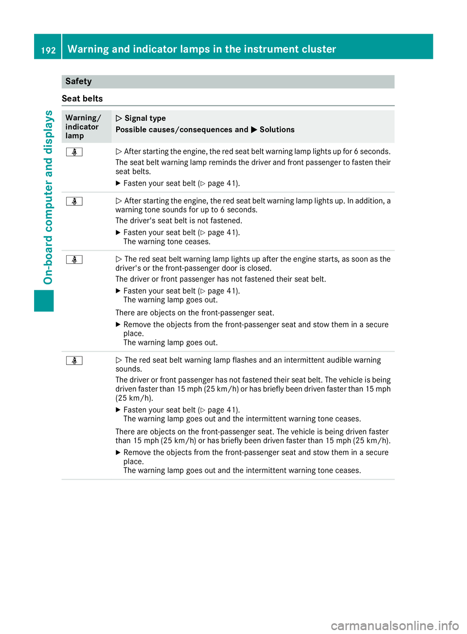
üNAfter starting the engine, the red seat belt warning lamp lights up for 6 seconds.
The seat belt warning lamp reminds the driver and front passenger to fasten their
seat belts.
XFasten your seat belt (Ypage 41).
üN After starting the engine, the red seat belt warning lamp lights up. In addition, a
warning tone sounds for up to 6 seconds.
The driver's seat belt is not fastened.
XFasten your seat belt (Ypage 41).
The warning tone ceases.
üN The red seat belt warning lamp lights up after the engine starts, as soon as the
driver's or the front-passenger door is closed.
The driver or front passenger has not fastened their seat belt.
XFasten your seat belt (Ypage 41).
The warning lamp goes out.
There are objects on the front-passenger seat.
XRemove the objects from the front-passenger seat and stow them in a secure
place.
The warning lamp goes out.
üN The red seat belt warning lamp flashes and an intermittent audible warning
sounds.
The driver or front passenger has not fastened their seat belt. The vehicle is being driven faster than 15 mph (25 km/h) or has briefly been driven faster than 15 mph
(25 km/h).
XFasten your seat belt (Ypage 41).
The warning lamp goes out and the intermittent warning tone ceases.
There are objects on the front-passenger seat. The vehicle is being driven faster
than 15 mph (25 km/h) or has briefly been driven faster than 15 mph (25 km/h).
XRemove the objects from the front-passenger seat and stow them in a secure
place.
The warning lamp goes out and the intermittent warning tone ceases.
192Warning and indicator lamps in the instrument cluster
On-board computer and displays