2018 MERCEDES-BENZ G-CLASS tow
[x] Cancel search: towPage 144 of 294
Collision warning
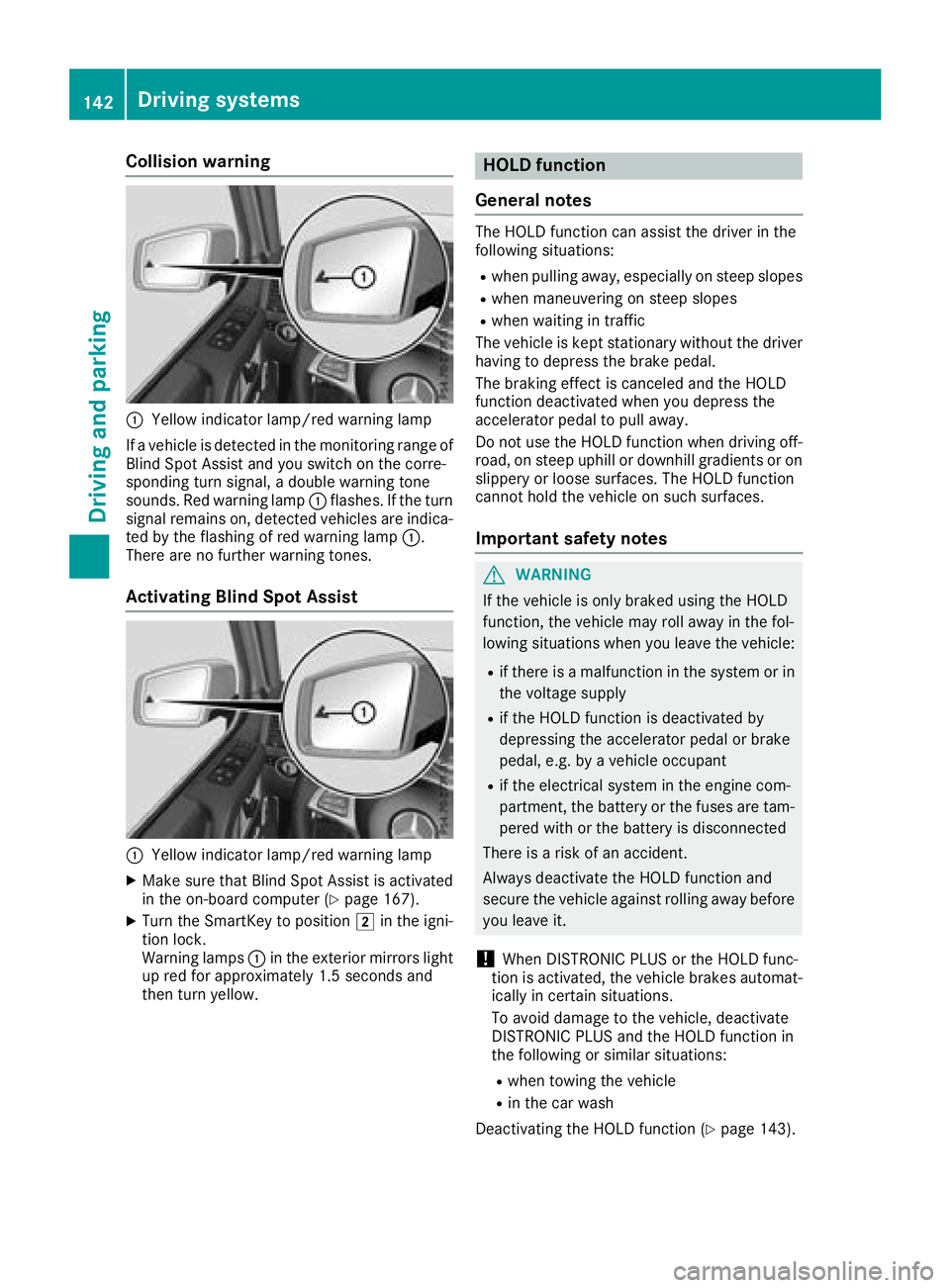
:Yellow indicator lamp/red warning lamp
If a vehicle is detected in the monitoring range of
Blind Spot Assist and you switch on the corre-
sponding turn signal, a double warning tone
sounds. Red warning lamp :flashes. If the turn
signal remains on, detected vehicles are indica-
ted by the flashing of red warning lamp :.
There are no further warning tones.
Activating Blind Spot Assist
:Yellow indicator lamp/red warning lamp
XMake sure that Blind Spot Assist is activated
in the on-board computer (Ypage 167).
XTurn the SmartKey to position 2in the igni-
tion lock.
Warning lamps :in the exterior mirrors light
up red for approximately 1.5 seconds and
then turn yellow.
HOLD function
General notes
The HOLD function can assist the driver in the
following situations:
Rwhen pulling away, especially on steep slopes
Rwhen maneuvering on steep slopes
Rwhen waiting in traffic
The vehicle is kept stationary without the driver having to depress the brake pedal.
The braking effect is canceled and the HOLD
function deactivated when you depress the
accelerator pedal to pull away.
Do not use the HOLD function when driving off-
road, on steep uphill or downhill gradients or on
slippery or loose surfaces. The HOLD function
cannot hold the vehicle on such surfaces.
Important safety notes
GWARNING
If the vehicle is only braked using the HOLD
function, the vehicle may roll away in the fol-
lowing situations when you leave the vehicle:
Rif there is a malfunction in the system or in the voltage supply
Rif the HOLD function is deactivated by
depressing the accelerator pedal or brake
pedal, e.g. by a vehicle occupant
Rif the electrical system in the engine com-
partment, the battery or the fuses are tam-
pered with or the battery is disconnected
There is a risk of an accident.
Always deactivate the HOLD function and
secure the vehicle against rolling away before
you leave it.
!When DISTRONIC PLUS or the HOLD func-
tion is activated, the vehicle brakes automat-
ically in certain situations.
To avoid damage to the vehicle, deactivate
DISTRONIC PLUS and the HOLD function in
the following or similar situations:
Rwhen towing the vehicle
Rin the car wash
Deactivating the HOLD function (
Ypage 143).
142Driving systems
Driving and parking
Page 145 of 294
Activationconditions
You can activat eth eHOLD function if:
Rth evehicl eis stationary
Rth eengin eis runnin gor if it has been auto -
matically switched off by th eECO start/sto p
function
Rth edriver's door is closed or your seat belt is
fastene d
Rtheparking brak eis release d
Rthetransmission is in position h,kori
RDISTRONI CPLU Sis deactivated
Activating the HOLD function
XMak esur ethat th eactivation condition sare
met .
XDepress th ebrak epedal .
XQuickl ydepress th ebrak epedal further until
ë appear sin th emultifunction display.
The HOLD function is activated. You can
release th ebrak epedal .
If depressing th ebrak epedal th efirst time does
no tactivat eth eHOLD function ,wait briefl yand
then tr yagain .
Deactivating the HOLD function
The HOLD function is deactivated automatically
if:
Ryou depress th eaccelerato rand th etrans -
mission is in position hork
Rthetransmission is in position j
Ryou depress thebrak epedal again wit h acer-
tai namount of pressur euntil ë disap-
pear sfrom th emultifunction display
Ryou activat eDISTRONI CPLU S
On steep uphil lor downhill inclines or if there is
a malfunction ,th etransmission may also be
automatically shifte dint oposition j.
Permanent all-wheel drive
!
Never to wthevehicl ewit hon eaxl eraised.
This may damag eth etransfer case. Damage
of this sor tis no tcovered by th eMercedes-
Benz Limited Warranty. All wheels mus t
remain either on th eground or be fully raised.
Observ eth einstruction sfor towin gth evehi-
cle wit hall wheels in full contact wit hth e
ground .
!When testing th eparking brake, only oper -
ate th evehicl ebriefl y(fo r a maximum of te n
seconds) on abrak edynamometer. Turn th e
SmartKey to position gor1 in th eignition
lock. You could otherwise damag eth edrive
train or th ebrak esystem.
!A function or performance test should only
be carrie dout on atwo-axle dynamometer.
Befor eyou operate th evehicl eon suc h a
dynamometer, pleas econsult aqualified
workshop .You could otherwise damag eth e
drive train or th ebrak esystem.
The all-whee ldrive system ensures that all four
wheels are permanentl ydriven .The all-whee l
drive system improve svehicl etraction together
wit hES P
®and 4ETS if adrive whee lspin sdue to
insufficien tgrip.
If adrive whee lspin sdue to insufficien tgrip:
ROnly depress th eaccelerato rpedal as far as
necessar ywhen pullin gaway.
RTak eyour foo toff th eaccelerator, slowly,
while th evehicl eis in motion .
In wintr ydrivin gconditions, always use winte r
tires (M+ Stires )and if necessary, snow chain s
(
Ypage 259). Only in this way can th emaximum
effec tof all-whee ldrive be achieved.
Fo rinformation on drivin goff-road, see
(
Ypage 129).
PARKTRONIC
Import ant safety notes
PARKTRONI Cis an electronic parking aid wit h
ultrasonic sensors. It monitors th earea around
your vehicl eusin gsix sensor sin th efron t
bumper and four sensor sin th erear bumper.
PARKTRONI Cindicates visually and audibly th e
distanc ebetween your vehicl eand an object.
PARKTRONI Cis only an aid. It is no t areplace -
men tfor your attention to your immediat esur -
roundings. You are always responsibl efor saf e
maneuvering, parking and exiting aparking
space. Mak esur ethat there are no persons,
animals or objects in th emaneuverin garea
while maneuverin gand parking in/leaving park -
ing spaces.
!When parking ,pay particular attention to
objects abov eor belo wthesensors, suc has
flower pot sor trailer drawbars .PARKTRONI C
does no tdetec tsuc hobjects when they are in
Driving systems143
Driving and parking
Z
Page 147 of 294

Warning displays
Warning display for the front area
:
Segments on the left-hand side of the vehi-
cle
;Segments on the right-hand side of the vehi-cle
=Segments showing operational readiness
The warning displays show the distance
between the sensors and the obstacle. The
warning display for the front area is located on
the dashboard above the center air vents. The
warning display for the rear area is located on
the headliner in the rear compartment.
The warning display for each side of the vehicle
is divided into five yellow and two red segments.
PARKTRONIC is operational if yellow segments
showing operational readiness =light up.
The selected transmission position and the
direction in which the vehicle is rolling deter-
mine which warning display is active when the
engine is running.
Transmission posi-
tionWarning display
hFront area activated
k, ior the vehicle
is rolling backwardsRear and front areas
activated
jNo areas activated
One or more segments light up as the vehicle
approaches an obstacle, depending on the vehi-
cle's distance from the obstacle.
From the:
Rsixth segment onwards, you will hear an inter-
mittent warning tone for approximately two
seconds.
Rseventh segment onwards, you will hear a
warning tone for approximately two seconds.
This indicates that you have now reached the minimum distance.
Deactivating/activating PARKTRONIC
:Indicator lamp
;Deactivates/activates PARKTRONIC
If indicator lamp :lights up, PARKTRONIC is
deactivated.
iPARKTRONIC is automatically activated
when you turn the SmartKey to position 2in
the ignition lock.
Towing a trailer
PARKTRONIC is deactivated for the rear area
when you establish an electrical connection
between your vehicle and a trailer.
Driving systems145
Driving and parking
Z
Page 149 of 294
The field of vision and other functions of the rear
view camera may be restricted due to additionalaccessories on the rear of the vehicle (e.g.
license plate holder, bicycle rack).
Activating/deactivating the rear view
camera
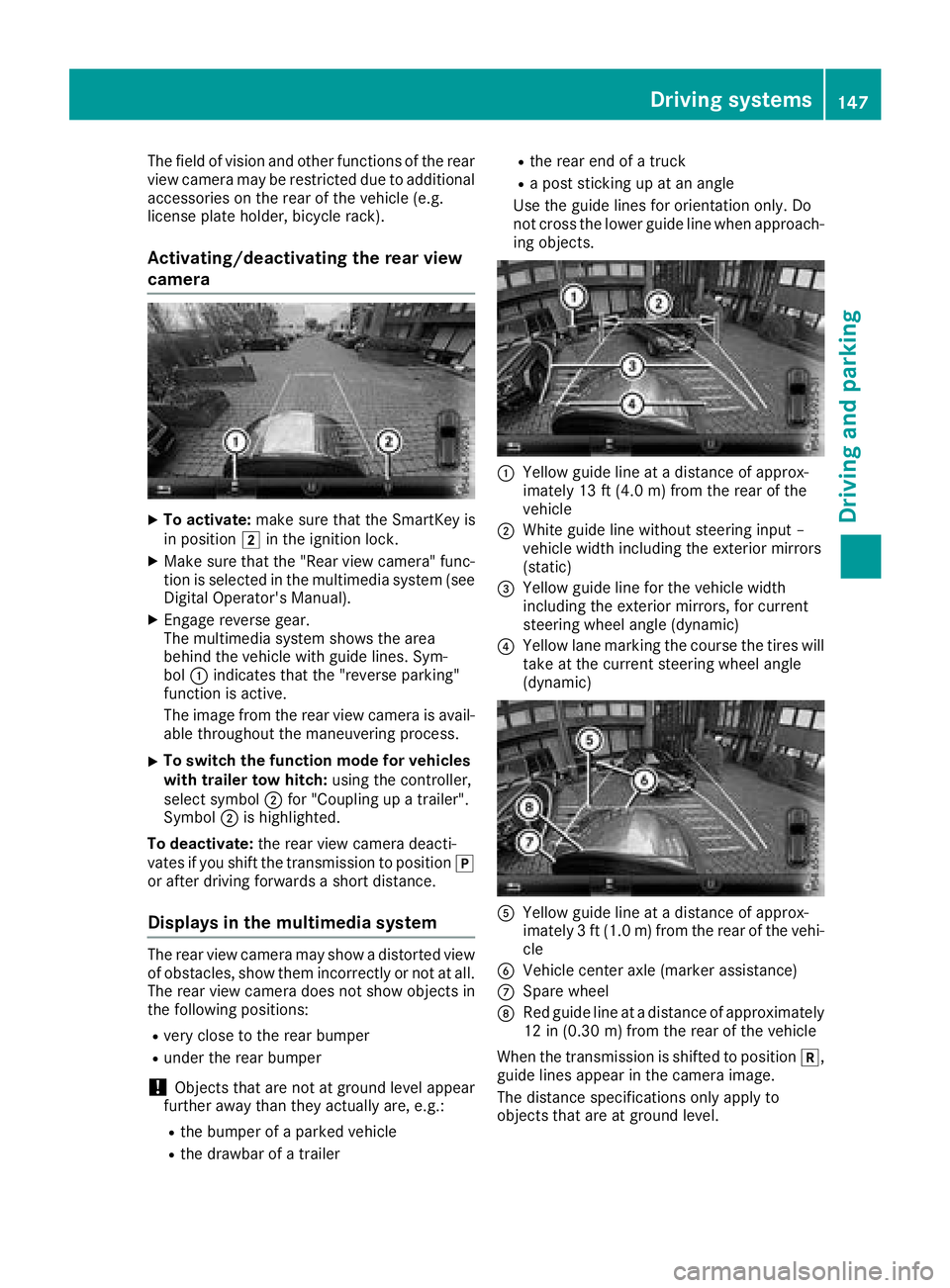
XTo activate: make sure that the SmartKey is
in position 2in the ignition lock.
XMake sure that the "Rear view camera" func-
tion is selected in the multimedia system (see
Digital Operator's Manual).
XEngage reverse gear.
The multimedia system shows the area
behind the vehicle with guide lines. Sym-
bol :indicates that the "reverse parking"
function is active.
The image from the rear view camera is avail-
able throughout the maneuvering process.
XTo switch the function mode for vehicles
with trailer tow hitch: using the controller,
select symbol ;for "Coupling up a trailer".
Symbol ;is highlighted.
To deactivate: the rear view camera deacti-
vates if you shift the transmission to position j
or after driving forwards a short distance.
Displays in the multimedia system
The rear view camera may show a distorted view
of obstacles, show them incorrectly or not at all.
The rear view camera does not show objects in
the following positions:
Rvery close to the rear bumper
Runder the rear bumper
!Objects that are not at ground level appear
further away than they actually are, e.g.:
Rthe bumper of a parked vehicle
Rthe drawbar of a trailer
Rthe rear end of a truck
Ra post sticking up at an angle
Use the guide lines for orientation only. Do
not cross the lower guide line when approach-
ing objects.
:Yellow guide line at a distance of approx-
imately 13 ft (4.0 m) from the rear of the
vehicle
;White guide line without steering input –
vehicle width including the exterior mirrors
(static)
=Yellow guide line for the vehicle width
including the exterior mirrors, for current
steering wheel angle (dynamic)
?Yellow lane marking the course the tires will take at the current steering wheel angle
(dynamic)
AYellow guide line at a distance of approx-
imately 3 ft (1.0 m) from the rear of the vehi-
cle
BVehicle center axle (marker assistance)
CSpare wheel
DRed guide line at a distance of approximately
12 in (0.30 m)from the rear of the vehicle
When the transmission is shifted to position k,
guide lines appear in the camera image.
The distance specifications only apply to
objects that are at ground level.
Driving systems147
Driving and parking
Z
Page 150 of 294
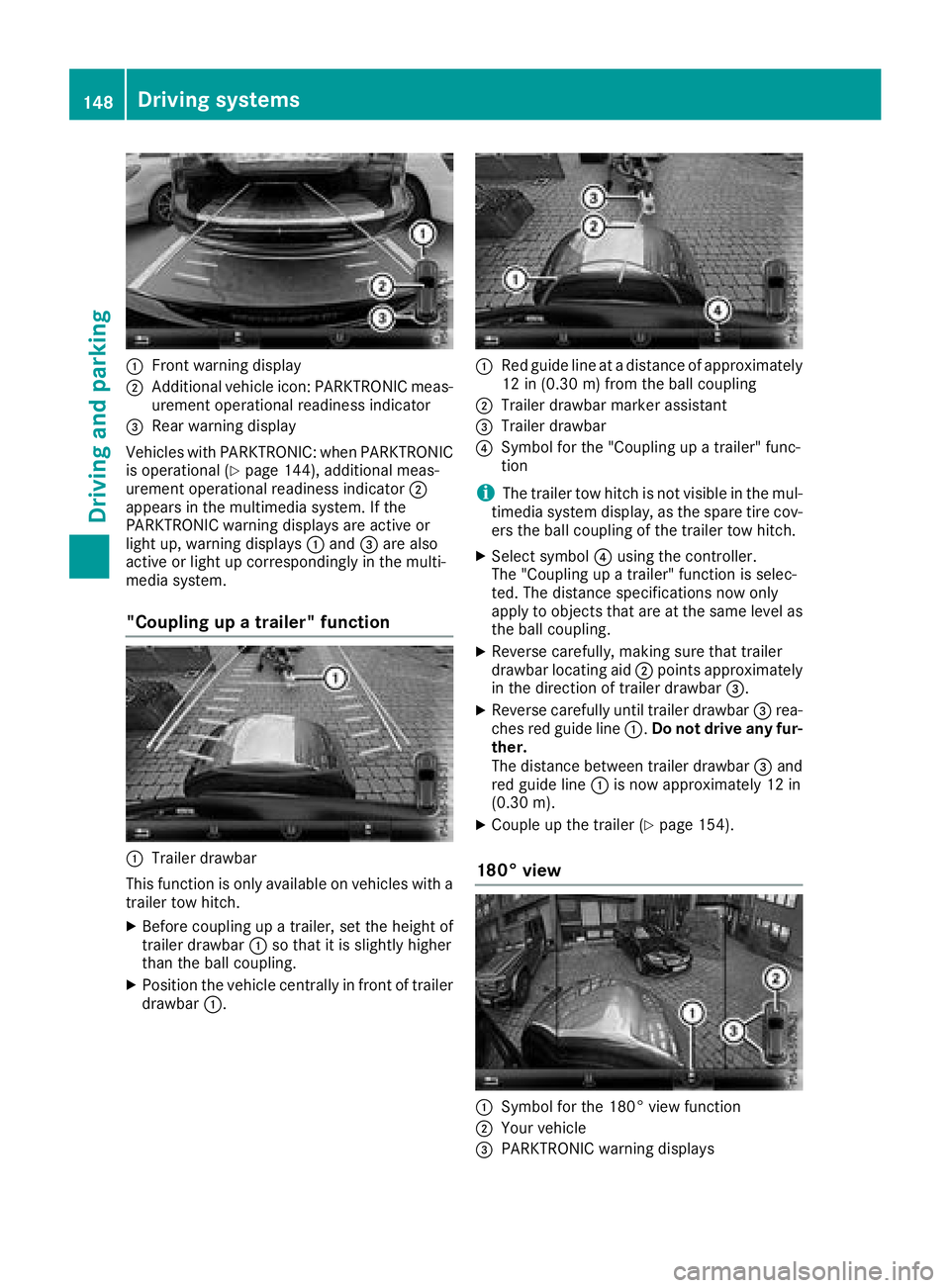
:Front warning display
;Additional vehicle icon: PARKTRONIC meas-
urement operational readiness indicator
=Rear warning display
Vehicles with PARKTRONIC: when PARKTRONIC
is operational (
Ypage 144), additional meas-
urement operational readiness indicator ;
appears in the multimedia system. If the
PARKTRONIC warning displays are active or
light up, warning displays :and =are also
active or light up correspondingly in the multi-
media system.
"Coupling up a trailer" function
:Trailer drawbar
This function is only available on vehicles with a
trailer tow hitch.
XBefore coupling up a trailer, set the height of
trailer drawbar :so that it is slightly higher
than the ball coupling.
XPosition the vehicle centrally in front of trailer
drawbar :.
:Red guide line at a distance of approximately
12 in (0.30 m) fromthe ball coupling
;Trailer drawbar marker assistant
=Trailer drawbar
?Symbol for the "Coupling up a trailer" func-
tion
iThe trailer tow hitch is not visible in the mul-
timedia system display, as the spare tire cov-
ers the ball coupling of the trailer tow hitch.
XSelect symbol ?using the controller.
The "Coupling up a trailer" function is selec-
ted. The distance specifications now only
apply to objects that are at the same level as
the ball coupling.
XReverse carefully, making sure that trailer
drawbar locating aid ;points approximately
in the direction of trailer drawbar =.
XReverse carefully until trailer drawbar =rea-
ches red guide line :.Do not drive any fur-
ther.
The distance between trailer drawbar =and
red guide line :is now approximately 12 in
(0.30 m).
XCoupleup the trailer (Ypage 154).
180° view
:Symbol for the 180° view function
;Your vehicle
=PARKTRONIC warning displays
148Driving system s
Driving an d parking
Page 151 of 294
You can also use the rear view camera to select
a 180° view.
When PARKTRONIC is operational (
Ypage 144),
a symbol for your own vehicle appears in the
multimedia system. If the PARKTRONIC warning
displays are active, warning displays =light up
in the multimedia system in yellow or red
accordingly.
Off-road driving systems
Transfer case
General notes
The vehicle has permanent all-wheel drive. The
front and rear axles are constantly driven.
For further information on driving off-road, see
(
Ypage 129).
Shift ranges
HIGH
RANGEPosition for all normal on-
road driving conditions
LOW RANGEOff-road gear for driving off-
road.
Also for use on steep uphill or
downhill gradients, especially
when towing a trailer.
The vehicle travels around
half the speed of on-road driv-
ing range HIGH RANGE. The
tractive power is correspond-
ingly higher.
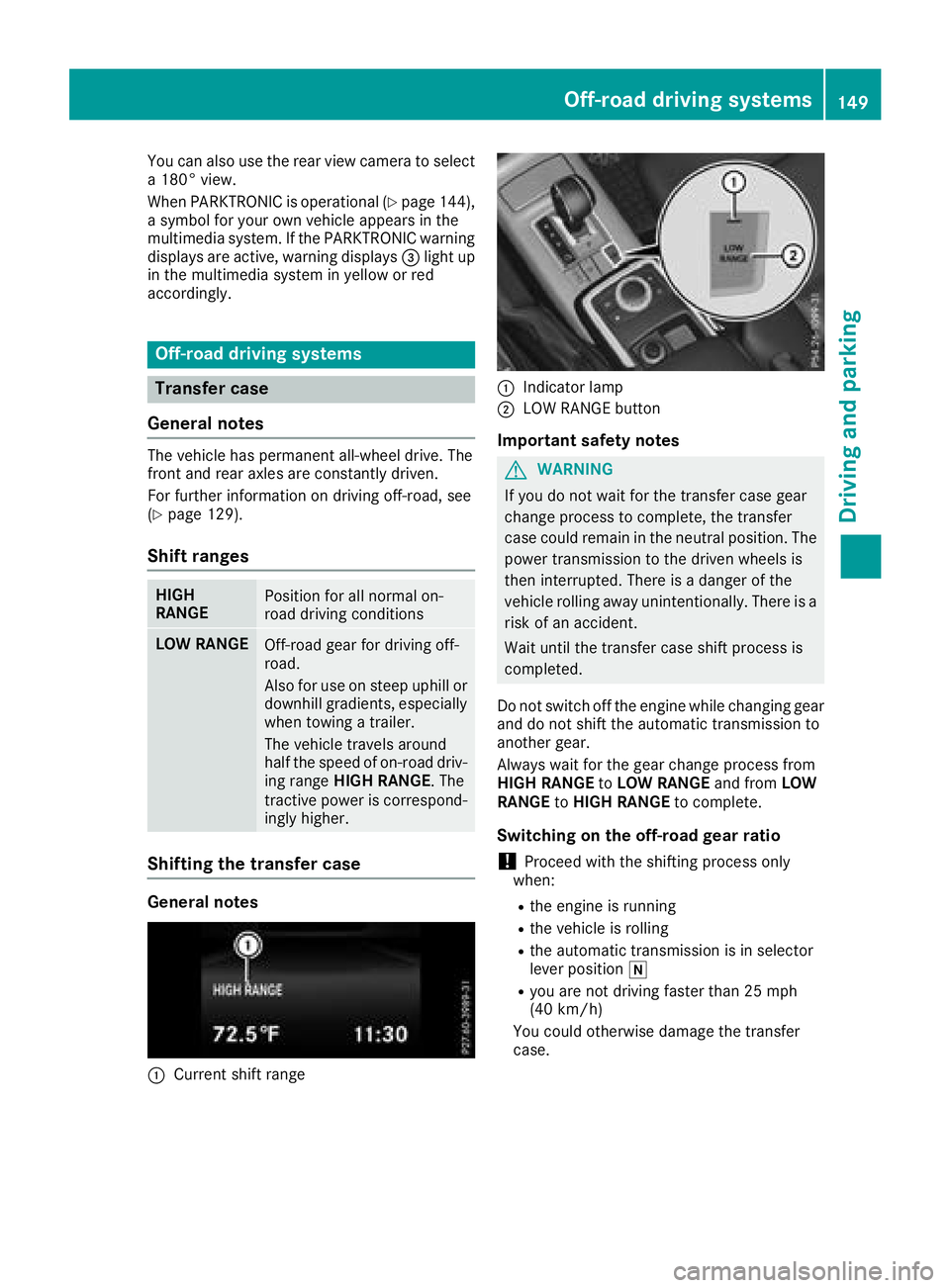
Shifting the transfer case
General notes
:Current shift range
:Indicator lamp
;LOW RANGE button
Important safety notes
GWARNING
If you do not wait for the transfer case gear
change process to complete, the transfer
case could remain in the neutral position. The power transmission to the driven wheels is
then interrupted. There is a danger of the
vehicle rolling away unintentionally. There is a
risk of an accident.
Wait until the transfer case shift process is
completed.
Do not switch off the engine while changing gear
and do not shift the automatic transmission to
another gear.
Always wait for the gear change process from
HIGH RANGE toLOW RANGE and fromLOW
RANGE toHIGH RANGE to complete.
Switching on the off-road gear ratio
!Proceed with the shifting process only
when:
Rthe engine is running
Rthe vehicle is rolling
Rthe automatic transmission is in selector
lever position i
Ryou are not driving faster than 25 mph
(40 km/h)
You could otherwise damage the transfer
case.
Off-road driving systems149
Driving and parking
Z
Page 155 of 294
Disengaging thedifferential lock s
You can disengage th edifferential locks in th e
followin gorder :; ,? ,= .
XTo simultaneously disengage all differen-
tial locks: press switch =.
Yellow activation indicator lamp sA and red
function indicator lamp s: go out .
Afte rapproximately three seconds of normal
driving, ABS, 4ETS ,ES P
®and BA Sare activa-
ted.
The Differential Locks Active ABS
and ESP Not Availablemessag edisap-
pear sin th emultifunction display and th e
å!÷warning lamps in the instru-
ment cluster go out.
XShift the transfer case to the HIGH RANGE
on-road position (Ypage 149).
If red function indicator lamps :do not go out
when disengaging the differential locks, stop
the vehicle safely in accordance with the traffic
conditions and then drive on. The load change
can disengage the differential locks.
Towing a trailer
Important safety notes
GWARNING
When the vehicle/trailer combination begins
to lurch, you could lose control of it. The vehi- cle/trailer combination could even rollover.
There is a risk of an accident.
On no account should you attempt to
straighten up the vehicle/trailer combination
by increasing the speed. Reduce vehicle
speed and do not countersteer. Apply the
brake as necessary.
GWARNING
If you install a ball coupling other than the one
delivered with the vehicle, the trailer tow hitch
and the rear axle may be overloaded. This
applies especially if the ball coupling in ques-
tion is longer or angled differently. This could
seriously impair the driving characteristics
and the trailer can come loose. There is a risk
of an accident.
Only install the ball coupling delivered with
the vehicle or a ball coupling that is designed to meet your trailer towing requirements. Do
not modify the ball coupling or the trailer tow
hitch.
GWARNING
If the ball coupling is not installed correctly or not secured with the bolt provided and the
corresponding spring cotter, the trailer may
come loose. There is a risk of an accident.
Always install and secure the ball coupling as
described. Before every journey, ensure that
the ball coupling is secured with the bolt and
the corresponding spring cotter.
!If you have a trailer tow hitch retrofitted,
changes to the engine cooling system may be
necessary, depending on the vehicle type.
If you have a trailer tow hitch retrofitted,
observe the anchorage points on the chassis
frame.
The installation of a trailer tow hitch is only per-
missible if a towing weight is specified in your
vehicle documents. If this is not the case, then
the vehicle is not approved for the towing of a
trailer.
For more information, please contact a qualified
specialist workshop.
Please observe the manufacturer's operating
instructions for the trailer coupling if a detach-
able trailer coupling is used.
Exceeding the maximum permissible nose-
weight of the trailer drawbar on the ball coupling may cause damage.
Damage may be caused to the following:
RTowing vehicle
RTrailer
RBall coupling
RTrailer tow hitch
The vehicle/trailer combination could become
unstable.
If the noseweight used is lower than the mini-
mum permissible noseweight, the vehicle/
trailer combination could also become unstable.
Towing a trailer153
Driving and parking
Z
Page 156 of 294

To avoid hazardous situations:
Rmake sure to check the noseweight before
each journey
Ruse a drawbar noseweight as close as possi-
ble to the maximum noseweight
Rdo not exceed the maximum permissible
noseweight
Rthe noseweight must not be lower than the
minimum permissible noseweight
Make sure that the following values are not
exceeded:
Rthe permissible trailer drawbar noseweight
Rthe permissible trailer load
Rthe permissible rear axle load of the towing
vehicle
Rthe maximum permissible gross vehicle
weight of both the towing vehicle and the
trailer
When backing up the vehicle towards the trailer,
make sure there is nobody between the trailer
and the vehicle.
The applicable permissible values, which must
not be exceeded, can be found:
Rin your vehicle documents
Ron the type plate for the trailer
Ron the vehicle identification plate
If the values differ, the lowest value applies.
You will find the values approved by the manu-
facturer on the vehicle identification plates and
those for the towing vehicle under "Technical
data" (
Ypage 291).
When backing up the vehicle towards the trailer,
make sure there is nobody between the trailer
and the vehicle.
Couple and uncouple the trailer carefully. If you
do not couple the trailer to the towing vehicle
correctly, the trailer could become detached.
When towing a trailer, your vehicle's handling
characteristics will be different in comparison
with when driving without a trailer.
The vehicle/trailer combination:
Ris heavier
Ris restricted in its acceleration and gradient-
climbing capability
Rhas an increased braking distance
Ris affected more by strong crosswinds
Rdemands more sensitive steering
Rhas a larger turning radius This could impair the handling characteristics.
Adapt your driving style accordingly. Maintain a
safe distance. Drive carefully.
When towing a trailer, always adjust your speed
to the current road and weather conditions. Do
not exceed the maximum permissible speed for
your vehicle/trailer combination.
Notes on towing a trailer
General notes
RDo not exceed the maximum permissible
speed for vehicle/trailer combinations in the
relevant country.
This lowers the risk of an accident.
ROnly install an approved trailer coupling on
your vehicle.
Further information on availability and on
installation is available from any authorized
Mercedes-Benz Center.
RThe bumpers of your vehicle are not suitable
for installing detachable trailer couplings.
RDo not install hired trailer couplings or other
detachable trailer couplings on the bumpers
of your vehicle.
RIf you do not need the ball coupling, remove
the ball coupling from the ball coupling
recess. This will reduce the risk of damage to the ball coupling.
When towing a trailer, set the tire pressure on
the rear axle of the towing vehicle for the max-
imum load. Further information on the tire pres-
sure table in the fuel filler flap (
Ypage 120).
Please note that when towing a trailer,
PARKTRONIC (
Ypage 143) and Blind Spot
Assist (Ypage 140) availability is limited or not
available at all.
The height of the ball coupling changes with the
load of the vehicle. If necessary, use a trailer
with a height-adjustable drawbar.
You will find permissible trailer loads under
"Technical data" (
Ypage 291).
Driving tips
XObserve the notes on ESP®trailer stabiliza-
tion (Ypage 61).
XOn long and steep downhill gradients, select
shift range 1,2or 3(Ypage 116) in good
time.
154Towing a trailer
Driving and parking