2018 MERCEDES-BENZ CLA COUPE lights
[x] Cancel search: lightsPage 226 of 326
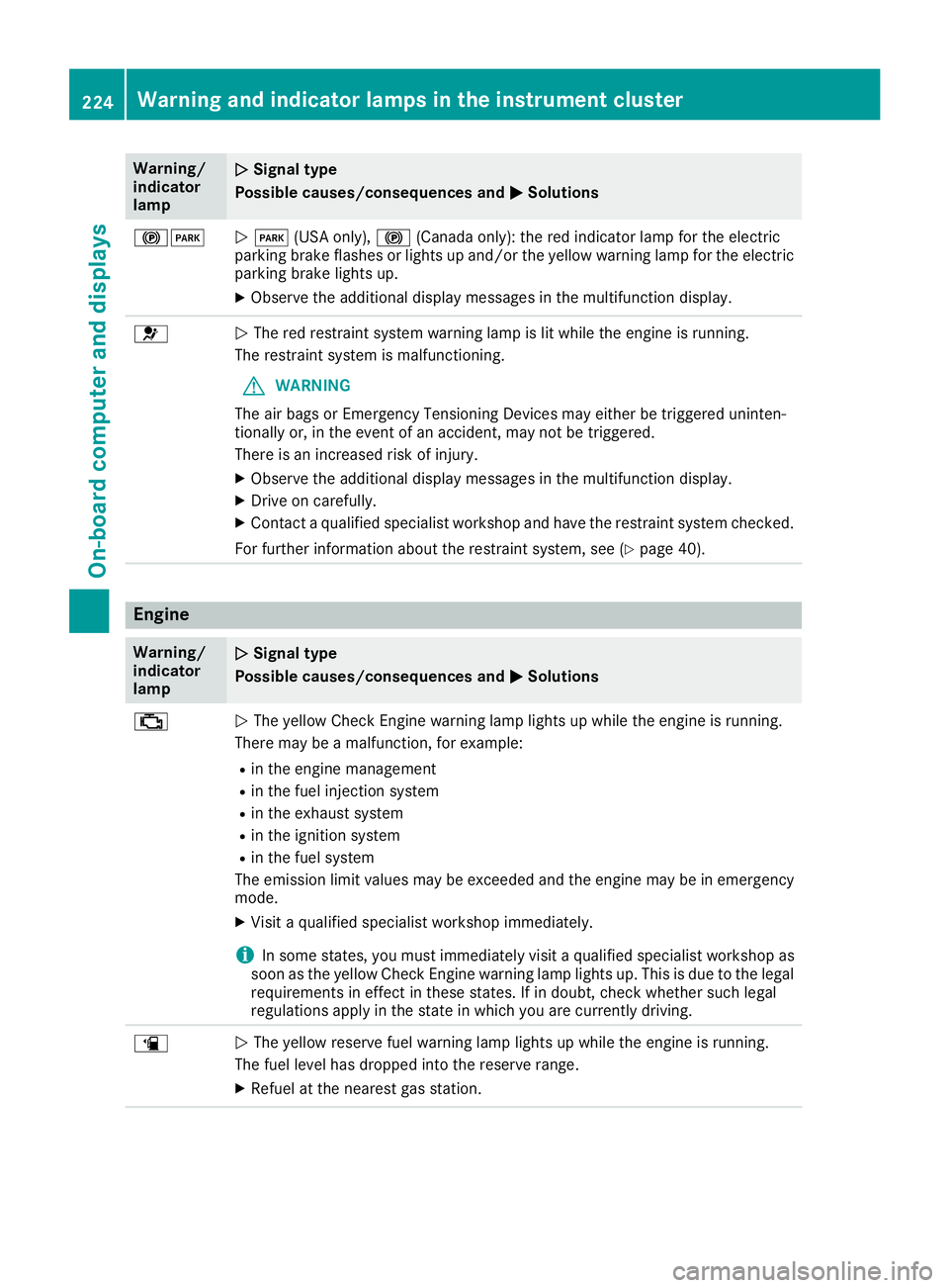
Warning/
indicator
lampNSignal type
Possiblec auses/consequences and M
Solutions
!FNF (USA only), !(Canada only): the red indicator lamp for the electric
parking brake flashes or lights up and/or the yellow warning lamp for the electric
parking brake lights up.
XObserve the additiona ldisplay messages in the multifunction display.
6N The red restraint system warning lamp is lit while the engine is running.
The restraint system is malfunctioning.
GWARNING
The air bagsorE mergency Tensioning Devices may either be triggeredu ninten-
tionally or, in the event of an accident, may not be triggered.
There is an increased risk of injury.
XObserve the additionald isplay messages in the multifunction display.
XDrive on carefully.
XContactaqualified specialist workshopa nd have the restraint system checked.
For further information about the restraint system, see (
Ypage4 0).
Engine
Warning/
indicator
lampNSignal type
Possiblec auses/consequences and M
Solutions
;NThe yellow Check Engine warning lamp lights up while the engine is running.
There may be amalfunction, for example:
Rin the engine management
Rin the fuel injection system
Rin the exhaust system
Rin the ignitio nsystem
Rin the fuel system
The emission limitv alues may be exceededa nd the engine may be in emergency
mode.
XVisitaq ualified specialist workshopi mmediately.
iIn some states, you must immediatel yvisit aqualified specialist workshopa s
soon as the yellow Check Engine warning lamp lights up. This is due to the legal
requirements in effect in these states. If in doubt, check whethers uch legal
regulations apply in the state in which you are currently driving.
æN The yellow reserve fuel warning lamp lights up while the engine is running.
The fuel levelh as dropped into the reserve range.
XRefuel at the neares tgas station.
224Warning and indicator lamps in the instrument cluster
On-board computer and displays
Page 227 of 326
Warning/
indicator
lampNSignal type
Possiblec auses/consequences and M
Solutions
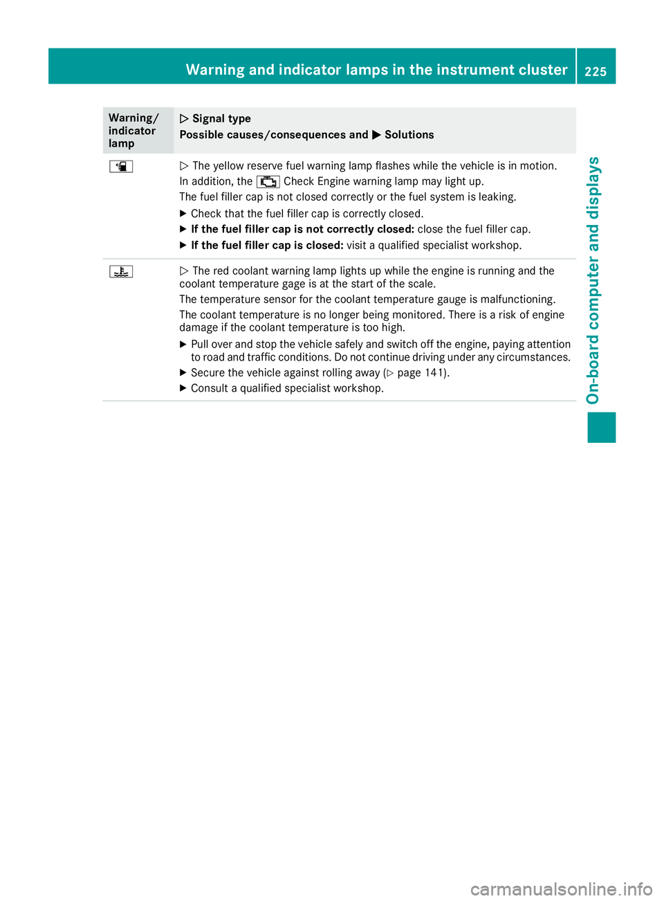
æNThe yellow reserve fuel warning lamp flashes while the vehicleisinm otion.
In addition, the ;Check Engine warning lamp may light up.
The fuel filler cap is not closed correctly or the fuel system is leaking.
XCheck that the fuel filler cap is correctly closed.
XIf the fuel filler cap is not correctly closed: close the fuel filler cap.
XIf the fuel filler cap is closed:visitaqualified specialist workshop.
?NThe red coolant warning lamp lights up while the engine is running and the
coolant temperature gage is at the start of the scale.
The temperature sensor for the coolant temperature gauge is malfunctioning.
The coolant temperature is no longer being monitored.T here isarisk of engine
damage if the coolant temperature is too high.
XPul lover and stop the vehicles afelyand switch off the engine, paying attention
to road and traffic conditions. Do not continue driving under any circumstances.
XSecure the vehiclea gainst rolling away(Ypage141).
XConsult aqualified specialist workshop.
Warning and indicator lamps in the instrument cluster225
On-board computer and displays
Z
Page 229 of 326
Warning/
indicator
lampNSignal type
Possiblec auses/consequences and M
Solutions
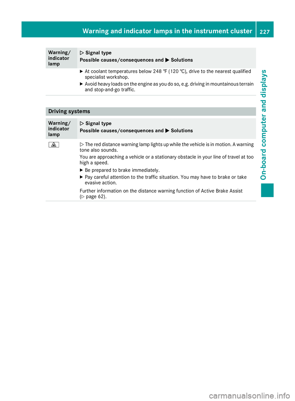
XAt coolant temperatures below 248 ‡(120 †), drive to the neares tqualified
specialist workshop.
XAvoid heavy loads on the engine as you do so, e.g. driving in mountainous terrain
and stop-and-go traffic.
Driving systems
Warning/
indicator
lampNSignal type
Possiblec auses/consequences and M
Solutions
·NThe red distance warning lamp lights up while the vehicleisinm otion.Awarning
tone als osounds.
You are approaching avehicleoras tationary obstacl einyourline of travel at too
high aspeed.
XBe prepared to brake immediately.
XPay carefu lattention to the traffic situation. You may have to brake or take
evasive action.
Further information on the distance warning function of Active Brake Assist
(
Ypage6 2).
Warning and indicator lamps in the instrument cluster227
On-board computer and displays
Z
Page 231 of 326
General notes
The multimedia system section in this Opera-
tor's Manualdescribes the basicp rinciples for
operation. More information can be found in the Digital Operator's Manual.
Important safety notes
GWARNING
If you operate information systems and com-
municatio nequipment integrated in the vehi-
cle when driving, you may be distracted from
the traffic situation. You could also lose con-
trol of the vehicle.T here isarisk of an acci-
dent.
Only operate this equipment when the traffic
situation permits. If you are not sure that this
is possible, park the vehicle paying attention
to traffic conditions and operate the equip-
ment when the vehicle is stationary.
You must observe the legalr equirements for the
country in which you are currently driving when
operating the multimedia system.
The multimedia system calculates the route to
the destination withoutt aking the following into
account, for example:
Rtraffic lights
Rstop and yield signs
Rparking or stopping restrictions
Rroad narrowing
Rother road and traffic rule sand regulations
The multimedia system may give incorrect nav-
igation recommendations if the actual street/
traffic situation does not correspond with the
digital map's data.
For example:
Rad iverted route
Rthe road layout or the direction of aone-way
street has been changed
For this reason, you must alwayso bserve road
and traffic rule sand regulations during your
journey. Roa dand traffic rule sand regulations
alwaysh ave priority over multimedia system
driving recommendations. Navigation announcements are intended to
direct you whiled
riving withoutdiverting your
attention from the road and driving.
Please alwaysu se this feature instead of con-
sulting the map display for directions. Looking
at the icons or map display can distract you from
traffic conditions and driving, and increase the
risk of an accident.
This equipment complies with FCC radiation
exposure limits set forth for uncontrolled equip-
ment and meets the FCC radiof requency (RF)
Exposure Guidelines in Supplement CtoOET65.
This equipment has very low levelsofRFe nergy
that is deemedtoc omply withoutmaximum
permissive exposure evaluation (MPE). How-
ever, it is recommended to insta
ll it atadistance
of at least 8inches (approx. 20 cm) betweent he
radiation source and aperson's body (not
including limbss uch as hands, wrists, feet and
legs).
GWARNING
Modifications to electronic components, their software as wellasw iring can impair their
function and/or the function of other net-
worked components. In particular, systems
relevant to safety could also be affected. As a
result, these may no longer function as inten-
ded and/or jeopardize the operating safety of
the vehicle.T here is an increasedr isk of an
accident and injury.
Never tamper with the wiring as wellase lec-
tronic components or their software .You
shoul dhave all work to electricala nd elec-
tronic equipment carried out at aqualified
specialist workshop.
Function restrictions
For safety reasons, some functions are restric-
ted or unavailable whilet he vehicle is in motion.
You willn otice this, for example, because either
you willn ot be abletos elect certain menu items
or am essag ewillappear to this effect.
Function restrictions229
Multimedia system
Z
Page 255 of 326
XTo start program mode:press and holdone
of buttons ;to? on the integrated garage
door opener.
The garag edooro penerisn ow in program
mode. After ashort time ,indicator lamp :
lights up yellow.
Indicato rlam p: lights up yellow as soona s
button ;,=or? is stored for the first time.
If the selecte dbutton hasa lready been pro-
gramed,i ndicator lamp :will onlyl ight up
yellow afte rten seconds have elapsed.
XReleas ebutton ;, =or?.I ndicator
lamp :flashesy ellow.
XTo program the remote control: point
garag edoorremote control Atoward sbut-
tons ;to? on the rear-view mirror at adis-
tance of 2to8in(5t o20c m).
XPress and hol dbutton Bon remote control
A unti lindicator lamp :lights up green.
Whe nindicator lamp :lights up green: pro-
gramming is finished.
Whe nindicator lamp :flashesg reen: pro-
gramming wa ssuccessful. The next step is to
synchronize the rolling code(
Ypage 253).
XReleas ebutton Bon remote control Afor
the garag edoord rive system.
If indicator lamp :lights up red:r epeatthe
programing procedur efor the corresponding
button on the rear-view mirror. Whe ndoing
so, var ythe distance between remote control
A and the re
ar-view mirror.
The required distance between remote con-
trol Aand the integrated garag edooropener
depends on the garag edoord rive system.
Several attempts might be necessary.Y ou
shoul dtest every positio nfor at least
25 seconds before trying another position.
Synchronizin gthe rolling code
Paya ttentio ntothe "Important safety notes"
(Ypage 252).
If the garag edoors ystem uses arolling code,
yo uw illa lsoh avetos ynchronize the garage
door system with the integrated garag edoor
opene rinthe rear-view mirror. To do thisy ouwill
nee dtou sethe programming button on the door
drive controlp anel.T he programming button
maybel ocate dind ifferent place sdepen ding on
the manufacturer. It is usuall yloc ate dont he
door drive uni tonthe garag eceiling.
Familiarize yoursel fwitht he garag edoord rive
operating instructions, e.g .under "Program- ming additional remote controls", before carry-
ing outt
he following steps.
Your vehicl emustbew ithinr each of the garage
door or gate opene rdrive. Make sure thatn ei-
ther your vehicl enor any persons/objects are
present withint he sweepofthe door or gate.
XTurn the SmartKey to position 2in the ignition
lock (Ypage 122).
XGe toutof the vehicle.
XPress the programming button on the door
drive unit.
Usually ,you now have 30 seconds to initiate
the next step.
XGe tinto the vehicle.
XPress previously programed button ;,=
or ? on the integrated garag edooro pener
repeatedly and in quick succession unti lthe
door closes.
The rolling codes ynchronizatio nist hen com-
plete.
Note sonp rogrammin gthe remote con-
trol
Canadia nradio frequency laws require a"break"
(o ri nterruption) of the transmission signals
afte rbroadcasting for afew seconds. Therefore,
thes esignals mayn ot last long enough for the
integrated garag edooro pener. The signalisn ot
detectedd uring programming. Comparable with
Canadia nlaw ,someU .S. garag edooro peners
also feature a"break".
Proceedasf ollows:
Rif youliveinC anada
Rif yo uhaved ifficultie sprogramming the
garag edooro pener(regardless of where you
live) as yo ufollo wthe programming steps.
XPress and hol done of buttons ;to? on the
integrated garag edooro pener.
After ashort time ,indicator lamp :lights up
yellow.
XReleas ethe button.
Indicato rlam p: flashesy ellow.
XPress button Bof garag edoorre mote con-
trol Afor two seconds, then release it for two
seconds.
XPress button Bagai nfor two seconds.
XRepeat thiss equence on button Bof remote
control Aunti lindicator lamp :lights up
green.
Whe nindicator lamp :lights up green: pro-
gramming is finished.
Features253
Stowag eand featur es
Z
Page 256 of 326
When indicator lamp:flashes green: pro-
gramming was successful. The next step is to
synchronize the rolling code.
XRelease button Bof remotec ontrolAof the
garage door drive.
If indicator lamp :lights up red: repeat the
programmingp rocess for the corresponding
button on the rear-view mirror. When doing
so, vary the distanc ebetween remotec ontrol
A and the rear-view mirror.
The required distanc ebetween remotec on-
trol Aand the integrated garage door opener
depends on the garage door drive system.
Several attempts might be necessary. You
should test every position for at least
25 seconds before trying another position.
Problems when programming
If you are experiencing problems programming
the integrated garage door opener on the rear-
view mirror, take not eofthe following instruc-
tions:
RCheck the transmitter frequenc yused by
garage door drive remotec ontrolAand
whether it is supported. The transmitter fre-
quency can usually be found on the back of
remotec ontrolAfor the garage door drive.
The integrated garage door opener is com-
patible with devices that have units which
operate in the frequenc yrange of 280 to
433 MHz.
RReplace the batteries in garage door remote
control A.This increases the likelihood that
garage door remotec ontrolAwill transmit a
stron gand precise signal to the integrated
garage door opener.
RWhen programming, hold remotec ontrolA
at varying distances and angles from but-
tons ;to? which you are programming. Try
various angles at adistanc ebetween 2and
8i nches (5to 20 cm) or at the same angle but
at varying distances.
RIf another remotec ontrolAis available for
the same garage door drive, repeat the same
programmings teps with this remotec ontrol
A.B eforep erforming these steps, make sure
that new batteries have been installed in
garage door drive remotec ontrolA.
RNote that some remotec ontrols only transmit
for alimited amount of time (the indicator
lamp on t
he remotec
ontrol goes out). Press button
Bon remotec ontrolAagain before
transmission ends.
RAlign the antenna cable of the garage door
opener unit. This can improve signal recep-
tion/transmission.
Opening/closing the garage door
After it has been programmed, the integrated
garage door opener performst he function of the
garage door system remotec ontrol. Please also
read the operating instruction sfor the garage
door system.
XTurn the SmartKey to position 2in the ignition
lock (Ypage 122).
XPress button ;,=or? which you have
programmed to operate the garage door.
Garage door system with afixed code: indi-
cator lamp :lights up green.
Garage door system with arolling code: indi-
cator lamp :flashes green.
The transmitter will transmit asignal as long
as the button is pressed. The transmission is
halted after amaximum of ten seconds and
indicator lamp :lights up yellow.
XPress button ;,=or? again if necessary.
Clearing the memory
Make sure that you clear the memory of the
integrated garage door opener before selling the
vehicle.
XTurn the SmartKey to position 2in the ignition
lock (Ypage 122).
XPress and hold buttons ;and ?.
The indicator lamp initially lights up yellow
and then green.
XRelease buttons ;and ?.
The memory of the integrated garage door
opener in the rear-view mirror is cleared.
254Features
Stowage and features
Page 267 of 326
Cleaning wiper blades
GWARNING
You coul dbecome trapped by th ewindshield
wipersift heys tart moving while cleanin gthe
windshield or wiper blades.T hereisarisko f
injury.
Always switch off th ewindshield wipersa nd
th ei gnition before cleanin gthe windshield or
wiper blades.
!Only fold th ewindshield wipersa way from
th ew indshield when vertical. Otherwise, you
will damaget hehood.
!Do no tpull th ewiper blade. Otherwise, the
wiper blade coul dbedamaged.
!Do notclean wiper blades to ooften and do
no trub them to ohard .Otherwise, th egraph-
ite coatin gcoul dbed amaged. This could
caus ewiper noise.
!Holdthe wiper arm securely when folding
back .The windshield coul dbedamaged if the
wiper arm smacks against it suddenly.
XFol dthe windshield wiper arm saway from the
windshield.
XCarefully clean th ewiper blades withad amp
cloth.
XFol dthe windshield wiper arm sback again
before switching on th eignition.
Cleaning th eexterior lighting
!Only use cleanin gagents or cleanin gcloths
whicha re suitable for plastic light lenses.
Unsuitable cleanin gagents or cleanin gcloths
coul dscratch or damag ethe plastic light len-
ses.
XClean th eplastic lenses of th eexteri or lights
withaw et sponge and amild cleanin gagent,
e.g .M ercedes-Ben zcar shampoo or cleaning
cloths.
Cleaning th emirror turn signals
!Only use cleanin gagents or cleanin gcloths
that are suitable for plastic lenses.U nsuitable
cleanin gagents or cleanin gcloth scould
scratch or damaget heplastic lenses of the
mirror tur nsignals.
XClean th eplastic lenses of th emirror tur nsig-
nals in th eexteri or mirror housing usingaw et
sponge and mild cleanin gagent, e.g.
Mercedes-Ben zcar shampoo or cleaning
cloths.
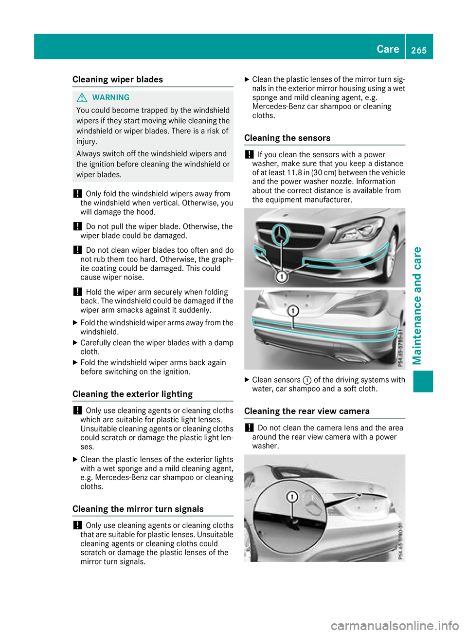
Cleaning th esensors
!If you clean th esensorsw ithapower
washer, mak esure that you keep adistance
of at least 11.8 in (30 cm)between the vehicl e
and th epower washer nozzle. Information
about th ecorrec tdistanc eisavailabl efrom
th ee quipment manufacturer.
XClean sensors :of th edriving systems with
water, car shampoo and asoftc loth.
Cleaning th erearv iew camera
!Do no tclean th ecamera lensa nd thearea
aroun dthe rear view camera with apower
washer.
Care265
Maintenance and care
Z
Page 297 of 326

shown in theServ.menu of the multifunction
display, see illustration (example).
For information on the message display, refer to
the "Checking the tire pressure electronically"
section (
Ypage 296).
Important safety notes
GWARNING
Each tire, including the spare (if provided),
should be checked at least once every two
weeks when cold and inflated to the pressure recommended by the vehicle manufacturer
on the Tire and Loading Information placard
on the driver's door B-pillar or the tire pres-
sure label on the inside of the fuel filler flap. If
your vehicle has tires of adifferent size than
the size indicated on the Tire and Loading
Information placard or, if available, the tire
pressure label,y ou should determine the
proper tire pressure for those tires.
As an added safety feature, your vehicle has
been equipped with atire pressure monitoring
system (TPMS) that illuminates alow tire pres-
sure telltale when one or more of your tires
are significantly underinflated. Accordingly,
when the low tire pressure telltale lights up,
you should stop and check your tires as soon
as possible,a nd inflate them to the proper
pressure. Driving on asignificantly underin-
flated tire causes the tire to overheat and can
lead to tire failure.
Underinflation also reduces fuel efficiency
and tire tread life, and may affect the vehicle's
handling and stopping ability. Please note that the TPMS is not asubstitute for proper tire
maintenance, and it is the driver's responsi-
bility to maintain correct tire pressure, even if
underinflation has not reached the level to
trigger illumination of the TPMS low tire pres- sure telltale.
Your vehicle has also been equipped with a
TPMS malfunction indicator to indicate when
the system is not operating properly. The
TPMS malfunction indicator is combined with
the low tire pressure telltale. When the sys-
tem detects amalfunction, the warning lamp
will flash for approximately aminute and then
remain continuously illuminated. This
sequence will be repeated every time the vehi-
cle is started as long as the malfunction
exists. When the malfunction indicator is illu-
minated, the system may not be able to detect
or signal low tire pressure as intended.
TPMS malfunctions may occur for avariety of
reasons, including the installation of incom-
patible replacement or alternate tires or
wheels on the vehicle that prevent the TPMS
from functioningp roperly. Always check the
TPMS malfunction telltale after replacing one
or more tires or wheels on your vehicle to
ensure that the replacement or alternate Tires
and wheels allow the TPMS to continue to
function properly.
It is the driver's responsibility to set the tire
pressure to that recommended for cold tires
which is suitable for the operating situation
(
Ypage 290). Note that the correct tire pressure
for the current operating situation must first be
taught-in to the tire pressure monitor. If asub-
stantial loss of pressure occurs, the warning
threshold for the warning message is aligned to
the taught-in reference values. Restart the tire
pressure monitor after adjusting the pressure of
the cold tires (
Ypage 297). The current pres-
sures are saved as new reference values. As a
result, awarning message will appearift he tire
pressure drops significantly.
The tire pressure monitor does not warn you of
an incorrectly set tire pressure. Observe the
notes on the recommended tire pressure
(
Ypage 290).
The tire pressure monitor is not able to warn you
of as udden loss of pressure, e.g. if the tire is
penetrated by aforeign object. In the event of a
sudden loss of pressure, bring the vehicle to a
halt by braking carefully.A void abrupt steering
movements.
Tire pressure295
Wheels and tires
Z