Page 93 of 614
Conversation Mirror
Located in the overhead console there is a conversation
mirror to view all the passengers in the vehicle. Push the
panel to release the drop down mirror. Raise the mirror and
push to latch it back in the stowed position.
Power Mirrors — If Equipped
The power mirror controls are located on the driver-side
door trim panel.
The power mirror controls consist of mirror select buttons
and a four-way mirror control switch. To adjust a mirror,
push either the L (left) or R (right) to select the mirror that
you want to adjust.
NOTE:A light in the selected button will illuminate
indicating the mirror is activated and can be adjusted.
Using the mirror control switch, push on any of the four
arrows for the direction that you want the mirror to move.
Conversation Mirror
Power Mirror Controls
3
GETTING TO KNOW YOUR VEHICLE 91
Page 96 of 614

Headlight Switch
The headlight switch is located on the left side of the
instrument panel. The switch controls the operation of the
headlights, parking lights, instrument panel lights, interior
lights and the fog lights.Rotate the headlight switch clockwise to the second detent
for parking light and instrument panel light operation.
Rotate the headlight switch to the third detent for head-
light, parking light and instrument panel operation.
Daytime Running Lights — If Equipped
The headlights or LED light bars on your vehicle will
illuminate when the vehicle is started. This provides a
constant lights on condition until the ignition is turned
OFF. If the parking brake is applied, the Daytime Running
Lights (DRL) will turn off. Also, if a turn signal is activated,
the DRL lamp on the same side of the vehicle will turn off
for the duration of the turn signal activation. Once the turn
signal is no longer active, the DRL lamp will illuminate.
High/Low Beam Switch
When the headlights are turned on, pushing the multifunc-
tion lever toward the instrument panel will switch from
low beams to high beams. Pulling back to the neutral
position returns the headlights to the low beam operation.
Headlight Switch
1 — Rotate Headlight Switch
2 — Ambient Dimmer Control
3 — Instrument Panel Dimmer
4 — Fog Lamps Button 94 GETTING TO KNOW YOUR VEHICLE
Page 97 of 614

Automatic High Beam — If Equipped
The Automatic High Beam system provides increased
forward lighting at night by automating high beam control
through the use of a digital camera mounted on the
windshield. This camera detects vehicle specific light and
automatically switches from high beams to low beams
until the approaching vehicle is out of view.
NOTE:Broken, muddy, or obstructed headlights and tail-
lights of vehicles in the field of view will cause headlights
to remain on longer (closer to the vehicle). Also, dirt, film
and other obstructions on the windshield or camera lens
will cause the system to function improperly.
To Activate
1. Select “Automatic High Beams — ON” through the Uconnect system. Refer to �Uconnect Settings” in “Mul-
timedia” for further information.
2. Rotate the headlight switch clockwise to the AUTO position.
3. Push the multifunction lever away from you to switch the headlights to the high beam position. Refer to
“Multifunction Lever” for further information. NOTE:
This system will not activate until the vehicle is at,
or above 16 mph (25 km/h).
To Deactivate
Perform either of the following steps to deactivate the
Automatic High Beam system.
1. Select “Automatic High Beams — OFF” through the Uconnect System. Refer to “Uconnect Settings” in “Mul-
timedia” for further information.
2. Pull the multifunction lever toward you to switch the headlights from the high beam to the low beam position.
3. Rotate the headlight switch counterclockwise from the AUTO to the on position.
NOTE: Once active, the Automatic High Beam system will
stop functioning below 12 mph (20 km/h).
Flash-To-Pass
You can signal another vehicle with your headlights by
lightly pulling the multifunction lever toward you. This
will cause the high beam headlights to turn on, and remain
on, until the lever is released.
3
GETTING TO KNOW YOUR VEHICLE 95
Page 103 of 614

NOTE:Always remove any buildup of snow that prevents
the windshield wiper blades from returning to the off
position. If the windshield wiper switch is turned off and
the blades cannot return to the off position, damage to the
wiper motor may occur.
WARNING!
Sudden loss of visibility through the windshield could
lead to a collision. You might not see other vehicles or
other obstacles. To avoid sudden icing of the wind-
shield during freezing weather, warm the windshield
with the defroster before and during windshield
washer use.
Intermittent Wiper System
Use the intermittent wiper when weather conditions make
a single wiping cycle with a variable pause between cycles
desirable. Rotate the end of the wiper lever to the first
detent position, and then turn the end of the lever to select
the desired delay interval. There are four delay settings,
which allow you to regulate the wipe interval from a
minimum of one cycle every second to a maximum of
approximately 36 seconds between cycles. The delay inter-
vals will double in duration when the vehicle speed is
10 mph (16 km/h) or less.
Windshield Washers
To use the washer, pull the lever rearward toward you and
hold while spray is desired. If the lever is pulled while on
the intermittent setting, the wipers will turn on and operate
for several wipe cycles after the lever is released, and then
resume the intermittent interval previously selected. If the
lever is pulled while the wipers are in the off position, the
wipers will operate several wipe cycles, then turn off.
Mist Feature
Use the Mist feature when weather conditions make occa-
sional usage of the wipers necessary. Push the lever up-
ward to the MIST position and release for a single wiping
cycle.
NOTE: The mist feature does not activate the washer
pump; therefore, no washer fluid will be sprayed on the
windshield. The wash function must be used in order to
spray the windshield with washer fluid.
Rain Sensing Wipers — If Equipped
This feature senses rain or snowfall on the windshield and
automatically activates the wipers for the driver. This
feature is especially useful for road splash or overspray
from the windshield washers of the vehicle ahead. Rotate
3
GETTING TO KNOW YOUR VEHICLE 101
Page 108 of 614

IconDescription
Front Defrost Button
Press and release to change the current airflow setting to Defrost mode. The indicator illumi-
nates when this feature is on. Air comes from the windshield and side window demist outlets.
When the defrost button is selected, the blower level may increase. Use Defrost mode with
maximum temperature settings for best windshield and side window defrosting and defogging.
Performing this function will cause the ATC to switch into manual mode. If the front defrost
mode is turned off the climate system will return the previous setting.
Rear Defrost Button
Push and release the Rear Defrost Control button to turn on the rear window defroster and the
heated outside mirrors (if equipped). An indicator will illuminate when the rear window de-
froster is on. The rear window defroster automatically turns off after ten minutes.
Rear Climate Rear Climate Control Button Press and release this button to access the rear climate controls. The indicator will illuminate
when the rear climate controls are on.
Driver And Passenger Temperature Up And Down Buttons
Provides the driver and passenger with independent temperature control. Push the red button
on the faceplate or touchscreen or press and slide the temperature bar towards the red arrow
button on the touchscreen for warmer temperature settings. Push the blue button on the face-
plate or touchscreen or press and slide the temperature bar towards the blue arrow button on
the touchscreen for cooler temperature settings.
106 GETTING TO KNOW YOUR VEHICLE
Page 129 of 614
The hood release lever (to open the primary latch) and
safety latch (to open the secondary latch) must be released
to open the hood.
1. Pull the hood release lever located under the driver ’sside of the instrument panel.
2. Move to the outside of the front of the vehicle.
3. Push the safety latch release lever toward the passenger side of the vehicle. The safety latch is located behind the
center front edge of the hood. 4. Remove the support rod from the locking tab and insert
it into the seat located on the underside of the hood.
NOTE:
• Before lifting the hood, check that the wiper arms are not
in motion and not in the lifted position.
• While lifting the hood, use both hands.
• Vehicle must be at a stop and the automatic transmission
must be in park.
Hood Release Lever
Safety Latch Location
3
GETTING TO KNOW YOUR VEHICLE 127
Page 136 of 614

Gas props support the liftgate in the open position. How-
ever, because the gas pressure drops with temperature, it
may be necessary to assist the props when opening the
liftgate in cold weather.
NOTE:Allow the power system to open the liftgate.
Manually pushing or pulling the liftgate may activate the
liftgate obstacle detection feature and stop the power
operation or reverse its direction.
WARNING!
During power operation, personal injury or cargo
damage may occur. Ensure the liftgate travel path is
clear. Make sure the liftgate is closed and latched
before driving away.
Cargo Area Features
Cargo Area Storage
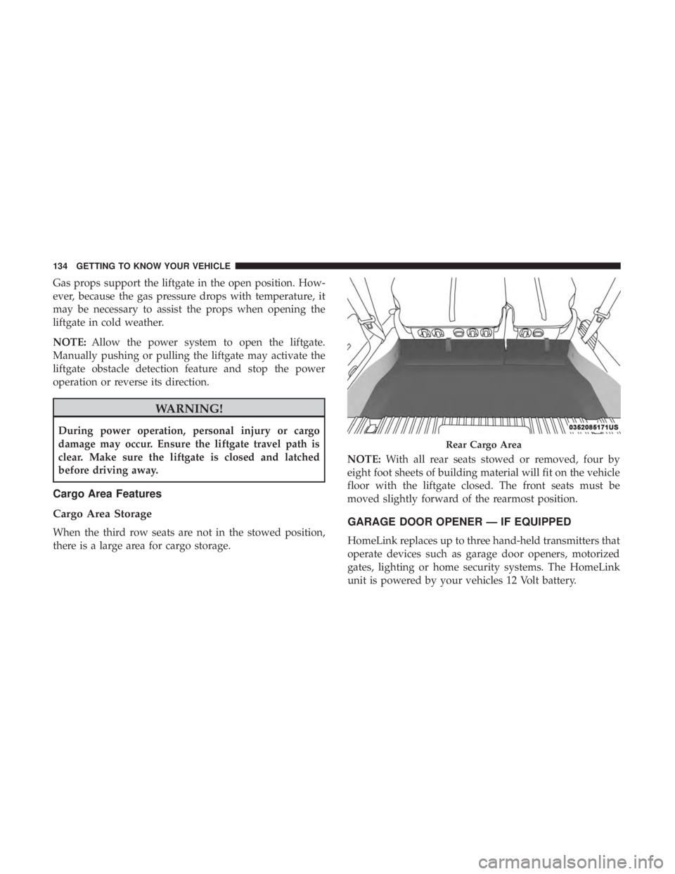
When the third row seats are not in the stowed position,
there is a large area for cargo storage. NOTE:
With all rear seats stowed or removed, four by
eight foot sheets of building material will fit on the vehicle
floor with the liftgate closed. The front seats must be
moved slightly forward of the rearmost position.GARAGE DOOR OPENER — IF EQUIPPED
HomeLink replaces up to three hand-held transmitters that
operate devices such as garage door openers, motorized
gates, lighting or home security systems. The HomeLink
unit is powered by your vehicles 12 Volt battery.
Rear Cargo Area
134 GETTING TO KNOW YOUR VEHICLE
Page 152 of 614
The door will slowly rotate to the full open position.
ROOF LUGGAGE RACK — IF EQUIPPED
The crossbars and side rails are designed to carry weight
on vehicles equipped with a luggage rack.The load must
not exceed 150 lbs (68 kg), and should be uniformly
distributed over the luggage rack crossbars.
The crossbars on your vehicle are delivered stowed within
the roof rack side rails. Crossbars should always be used
whenever cargo is placed on the roof rack. Check the straps
frequently to be sure that the load remains securely at-
tached. The roof rack does not increase the total load carrying
capacity of the vehicle. Be sure the total load of cargo inside
the vehicle plus that on the external rack does not exceed
the maximum vehicle load capacity.
Full Open Position
Roof Rack
1 — Side Rail
2 — Crossbar
150 GETTING TO KNOW YOUR VEHICLE