Page 19 of 614
�ROOF LUGGAGE RACK — IF EQUIPPED ......150
▫ Deploying The Crossbars .................151 ▫
Stowing The Crossbars ...................153
3
GETTING TO KNOW YOUR VEHICLE 17
Page 68 of 614

location below the door handle(s). Do not move your foot
sideways or in a sweeping motion or the sensors may not
detect the motion.
When a valid kicking motion is completed, the sliding door
will chime, the hazard lights will flash and the sliding door
will open almost instantaneously. This assumes all options
are enabled in the radio settings.
NOTE:
•To open the Hands-Free Sliding Doors requires a valid
Passive Entry key fob within 5 ft (1.5 m) of the door
handle. If a valid Passive Entry key fob is not within 5 ft
(1.5 m), the door will not respond to any kicks.
• The Hands-Free Sliding Door will only operate when the
transmission is in PARK.
• With every movement of the Hands-Free sliding doors,
an audible tone will sound and the turn signals will
flash. Refer to “Uconnect Settings” in “Multimedia” for
further information on turning these alerts on or off.
• If anything obstructs the power sliding side door while
it is closing or opening, the door will automatically
reverse to the closed or open position and an audible
tone will sound, provided it meets sufficient resistance.
The turn signals will flash with sliding door movements. •
If the power sliding doors encounters multiple obstruc-
tions within the same cycle, the system will automati-
cally stop.
The Hands-Free Sliding Doors feature may be turned off
through Uconnect Settings. Refer to “Uconnect Settings” in
“Multimedia” for further information. The Hands-Free
Sliding Doors feature should be turned off during Jacking,
Tire Changing, and Vehicle Service.
Child Locks
To provide a safer environment for small children riding in
the rear seats, the sliding doors are equipped with a Child
Protection Door Lock system.
To Engage The Child Protection Door Lock
1. Open the sliding side door.
2. On the rear of the sliding door, slide the Child Protection Door Lock control inward (toward the vehicle) to en-
gage the Child Protection Door Lock.
66 GETTING TO KNOW YOUR VEHICLE
Page 80 of 614
Fold-Flat
To fold the seat, lift the recliner lever to the full upward
position and push the seatback forward until it rests on the
seat cushion.
NOTE:The seatback may lock into the fold flat position.
Use the recline lever to unlock the seatback.
Second Row Removable Seat
The Easy Entry Slide second row seating does not stow in
the floor, but they are removable for added cargo space.
Removing Seat
1. Adjust seat to the full rearward position.
2. Lift the recline lever to fold the seatback flat against the seat cushion.
NOTE: Push downward on the seatback to make sure it is
in the locked position.
Fold-Flat Seat Recline Lever
Fold-Flat Seat Recline Lever
78 GETTING TO KNOW YOUR VEHICLE
Page 83 of 614
Manually Folding Third Row Seats — If Equipped
1. Lower the center head restraint down to the seatback bypushing the button on the guide and pushing the head
restraint down.
2. Pull release strap marked “1” to release the anchors.
3. Pull release strap marked “2” and tumble the seat rearward into the storage bin.
Release Strap “1”
Strap “2”
Stowed Third Row Seat
3
GETTING TO KNOW YOUR VEHICLE 81
Page 87 of 614

NOTE:To remove the head restraint, raise it as far as it can
go. Then, push the release button and the adjustment
button at the base of each post while pulling the head
restraint up. Seatback angle may need to be adjusted to
fully remove the head restraint. To reinstall the head
restraint, put the head restraint posts into the holes and
push downward. Then, adjust the head restraint to the
appropriate height.
WARNING!
• A loose head restraint thrown forward in a collision
or hard stop could cause serious injury or death to
occupants of the vehicle. Always securely stow re-
moved head restraints in a location outside the
occupant compartment.
• ALL the head restraints MUST be reinstalled in the
vehicle to properly protect the occupants. Follow the
re-installation instructions above prior to operating
the vehicle or occupying a seat.
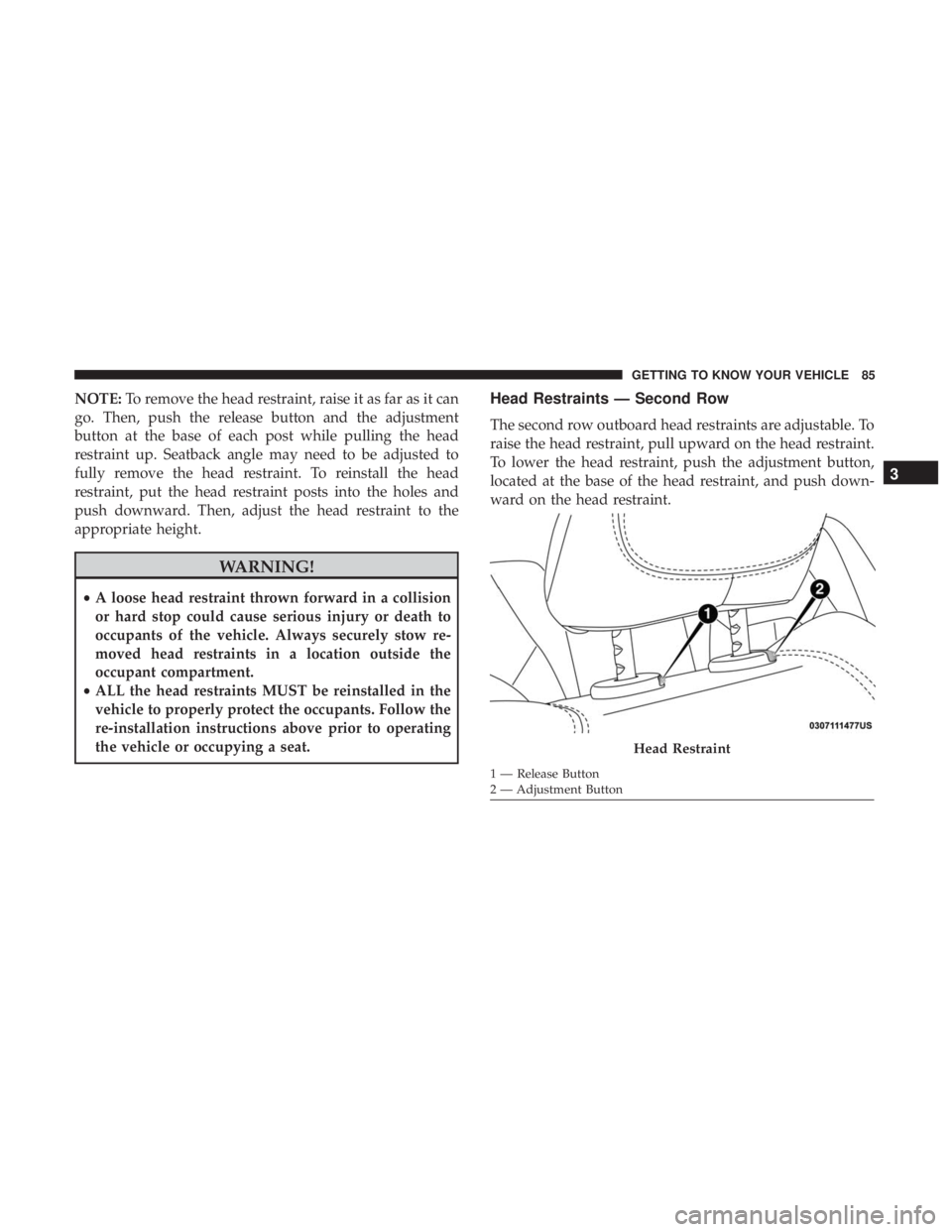
Head Restraints — Second Row
The second row outboard head restraints are adjustable. To
raise the head restraint, pull upward on the head restraint.
To lower the head restraint, push the adjustment button,
located at the base of the head restraint, and push down-
ward on the head restraint.
Head Restraint
1 — Release Button
2 — Adjustment Button
3
GETTING TO KNOW YOUR VEHICLE 85
Page 88 of 614

NOTE:To remove the head restraint, raise it as far as it can
go then push the release button and the adjustment button
at the base of each post while pulling the head restraint up.
Seatback angle may need to be adjusted to fully remove the
head restraint. To reinstall the head restraint, put the head
restraint posts into the holes and push downward. Then,
adjust the head restraint to the appropriate height.
WARNING!
• A loose head restraint thrown forward in a collision
or hard stop could cause serious injury or death to
occupants of the vehicle. Always securely stow re-
moved head restraints in a location outside the
occupant compartment.
• ALL the head restraints MUST be reinstalled in the
vehicle to properly protect the occupants. Follow the
re-installation instructions above prior to operating
the vehicle or occupying a seat.
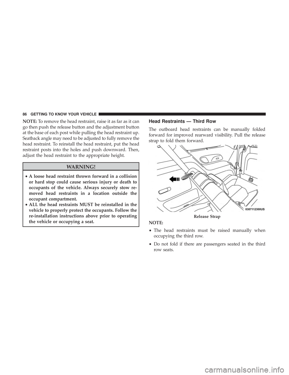
Head Restraints — Third Row
The outboard head restraints can be manually folded
forward for improved rearward visibility. Pull the release
strap to fold them forward.
NOTE:
• The head restraints must be raised manually when
occupying the third row.
• Do not fold if there are passengers seated in the third
row seats.
Release Strap
86 GETTING TO KNOW YOUR VEHICLE
Page 89 of 614

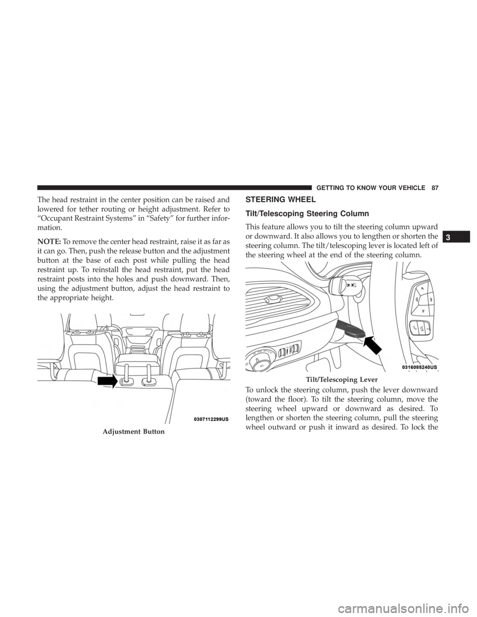
The head restraint in the center position can be raised and
lowered for tether routing or height adjustment. Refer to
“Occupant Restraint Systems” in “Safety” for further infor-
mation.
NOTE:To remove the center head restraint, raise it as far as
it can go. Then, push the release button and the adjustment
button at the base of each post while pulling the head
restraint up. To reinstall the head restraint, put the head
restraint posts into the holes and push downward. Then,
using the adjustment button, adjust the head restraint to
the appropriate height.STEERING WHEEL
Tilt/Telescoping Steering Column
This feature allows you to tilt the steering column upward
or downward. It also allows you to lengthen or shorten the
steering column. The tilt/telescoping lever is located left of
the steering wheel at the end of the steering column.
To unlock the steering column, push the lever downward
(toward the floor). To tilt the steering column, move the
steering wheel upward or downward as desired. To
lengthen or shorten the steering column, pull the steering
wheel outward or push it inward as desired. To lock the
Adjustment Button
Tilt/Telescoping Lever
3
GETTING TO KNOW YOUR VEHICLE 87
Page 91 of 614

WARNING!(Continued)
•Do not place anything on the steering wheel that
insulates against heat, such as a blanket or steering
wheel covers of any type and material. This may
cause the steering wheel heater to overheat.
MIRRORS
Inside Day/Night Mirror — If Equipped
A single ball joint mirror is used to allow the driver to
adjust up, down and left, right. Mirror should be adjusted
to center on the view through the rear window.
Headlight glare can be reduced by moving the small
control under the mirror to the night position (toward the
rear of the vehicle). The mirror should be adjusted while
set in the day position (toward the windshield).
Automatic Dimming Mirror — If Equipped
This mirror automatically adjusts for headlight glare from
vehicles behind you. You can turn the feature on or off by
pushing the button at the base of the mirror. A light to the
left of the button will illuminate to indicate when the
dimming feature is activated. The sensor to the right of the
button does not illuminate.
NOTE: This feature is disabled when the vehicle is in
REVERSE.
Manual Rearview Mirror
3
GETTING TO KNOW YOUR VEHICLE 89