Page 377 of 404

u. 00 .-< N l' N .-< 0 N > 00
Emergency situations
General
This chapter is intended for trained emergency
crews and working personnel who have the nec
essary tools and equipment to perform these
operations.
Starting by pushing or
towing
~ Note
Vehicles with an automatic transmission can
not be started by pushing or towing.
Jump starting
Preparation
If needed, the engine can be jump started by an
other vehicle battery.
Applies to: vehicles with plug-in hybrid drive: the
connection points for the jump start cable are
different
q page 102.
If the engine does not start because the vehicle
battery is drained, you can jump start the engine
using another vehicle battery. You need a jump
start cable to do this.
Both vehicle batteries must have 12 V nominal
voltage . The voltage capacity (Ah) of the vehicle
battery that is giving power must not be less
than the capacity of the drained vehicle battery.
Jump start cable
Only use a jump start cable with a large enough
diameter. Note the manufacturer's specifica
tions .
Only use a jump start cable with insulated termi
nal clamps.
Positive cable - usually red .
Negative cable -usually black.
Emergency situations
A WARNING
--
- Applies to: vehicles with plug-in hybrid
drive: you must
not give a jump start with
your vehicle . This could cause significant
damage to the electrical system in your ve
hicle
Q page 102.
-A drained vehicle battery can freeze at tem
peratures around 0
Q(. If the vehicle battery
is frozen, you must thaw it before connect
ing the jump start cables. If you do not, this
increases the risk of an explosion and chem
ical burns. After jump starting the vehicle,
drive to an authorized Audi dealer or author
ized Audi Service Facility immediately to
have the vehicle battery checked.
- The engine compartment is a dangerous
area and can cause serious injuries. Before
working in the engine compartment, read
and follow the warnings
Qpage 318.
- Handling the jump start cables incorrectly
may cause the vehicle battery to explode
and lead to serious injuries . To reduce the
risk of injury, observe the following:
- Do not touch the non-insulated parts of the
terminal clamps. The cable must also not
come into contact with vehicle components
that conduct electricity when it is connected
to the positive terminal. This can cause a
short circuit.
- Route the jump start cables so they cannot
get caught in the moving parts in the engine
compartment.
- To reduce the risk of chemical burns, do not
bend over the vehicle battery.
- The locking bolts on the battery cells must
be tightened securely.
- Keep ignition sources (open flames, burning
cigarettes, etc.) away from the vehicle bat
teries to reduce the risk of an explosion.
- Do not clamp the negative cable to fuel sys tem components or to the brake lines.
(LlJ} Note
- There must be no contact between the
vehicles, If there is, current could already be
.,.
375
Page 378 of 404

Emergency situations
flowing when connecting the positive termi
nals and the vehicle battery in the vehicle
providing the jump start cou ld be drained.
- Jump start cables can cause considerab le
damage to the vehicle electrical system if
they are connected incorrectly.
- The drained vehicle battery must be con
nected correctly to the electrical system.
- P lease note that the connecting process de
scribed below for the jump start cables is in
tended for when your vehicle is being jump
started. If you are jump starting another ve
hicle, do not connect the negative cable to
the negat ive terminal( -) on the drained ve
hicle battery, but rather connect it to a large
metal component that is bolted securely to
the engine block, or to the engine block it
se lf. If the vehicle battery in the vehicle be
ing jump started is not vented to the out
side, there is a risk of explosion due to hy
drogen gas.
@ Tips
If a car phone is installed, switch it off or
check the operating guide for what to do in
this situation.
A3 models: starting the engine
Both jump start cables must be connected in the
correct order!
F ig. 300 Ju mp starting using a vehicle batte ry in anot her
vehicle :@ - dra ined, @- providing cu rrent
Plug-in hybrid drive *: the connection points for
the jump start cables vary Q
page 102.
The vehicle battery is located on the left front
side of the engine compartment . Open the cover
to access the positive terminal of the vehicle bat-
376
tery. The procedure for connecting jump start ca
bles that is described next is designed to help
j ump start your vehicle .
Follow the information about the vehicle battery
Qpage 326 .
Preparations
1. Read the following carefully ¢ page 375,
Preparation.
2. Set the parking brake and select neutral on
vehicles with a manual transmission, or move
the selector lever to the P position on
vehicles with an automatic transmission .
3. Turn the ignition and electrical equipment
off in both vehicles.
Connecting/disconnecting the jump start
cable
4. Fold the battery cover upward.
5. Clamp the end of the red jump start cable to
the termina l
(D ¢ fig. 300 on the drained ve
hicle
battery @Q(D in Preparation on
page
375 .
6. Clamp the other end of the red jump start ca
ble to the positive terminal @on the vehicle
battery providing the current @.
7. Clamp the black end of the jump start cab le
preferably at the ground point, or on the
negative terminal of the vehicle battery@
on the vehicle providing the current @.
8. Clamp the other end of the black jump start
cable
only to the ground point © on your
vehicle @Q(D .
9. Route the jump start cables so they cannot
get caught in the moving parts in the engine
compartment.
Starting the engine
10. First start the engine in the vehicle giving the
charge and let it run at idle.
11. Now start the engine in the vehicle with the
dra ined vehicle battery and wait two to three
minutes until it "r uns smoothly".
12. If the engi ne does not start, stop the starting
procedure after 10 seconds and then repeat
it after approximately 30 seconds .
13. In the vehicle that is being jump started, switch the heater fan and rear window
..,,
Page 379 of 404

LL co ..... N
" N ..... 0 N > co
defroster on to reduce any voltage peaks that may occur when disconnecting the jumper
cables. The headlights must be switched
off.
14. While the engines are running , remove the
cables in
reverse order from the way they
were installed, as described in ¢
page 3 76.
Make sure the cables do not get caught in
moving engine components .
15. Fold the cover back on the battery correct ly .
16. Sw itch the heater fan and rear w indow de
froster
off.
Read and fo llow: ¢.&. in Preparation on
page 375
and ¢ (j) in Preparation on page 375.
(D Note
Do not use the negat ive termina l on the veh i
cle battery for jump star ting. A malfunction
could occ ur in the vehicle electrical system.
@ Tips
- Make sure that the connected positive ter
mina l clamps have sufficient contact with
metal.
- The vehicle battery in your vehicle vents to the outs ide so the battery gases d rain out of
the veh icle.
RS model s: starting the engine
Both jump start cables must be connected in the
correct order!
F ig . 301 Engine co mpartment : connector s for a c ha rge r
and jump star t cables
Em erge ncy s itua tions
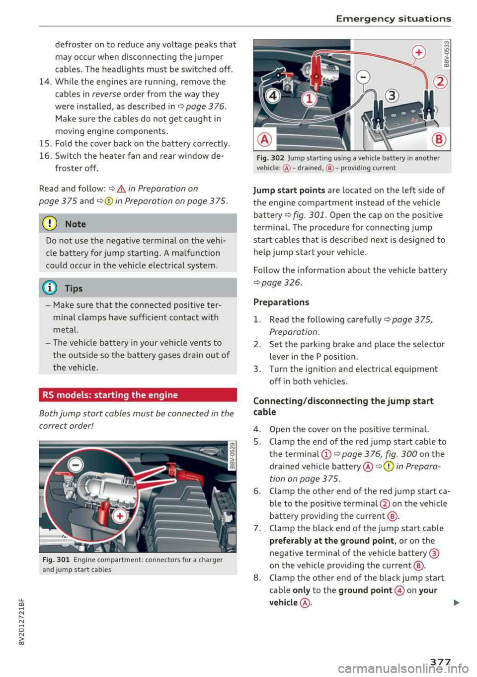
Fig. 302 Jump star ting using a ve hicle bat tery in anothe r
ve hicl e:@ -drained, @- prov id in g curren t
M
lri 0 > (X) m
Jump sta rt p oin ts are located on the left side of
the engine compartment instead of the vehicle
battery ¢
fig. 301. Open the cap on the positive
terminal. The procedure for connecting jump start cables that is described next is designed to
help jump start your vehicle .
Follow the information about the vehicle battery
¢ page 326.
Pr eparation s
1. Read the follow ing carefully ¢ page 375,
Preparation .
2. Set the parking brake and place the selector
lever in the P position.
3. Turn the ign ition and electrical equipment
off i n both vehicles .
Conn ecting /d is conn ect ing the jum p sta rt
cable
4. Open the cover on the posit ive terminal.
5. Clamp the end of the red jump start cable to the
termina l(!) ¢ page 3 76, fig. 300 on the
drained vehicle
battery @c:;>(Q) in Prepara
tion on page 375.
6. Clamp the other end of the red jump sta rt ca
ble to the positive terminal @on the veh icle
battery providing the current @.
7. Clamp the black end of the jump start cab le
prefer ably at the grou nd point , or on the
negative terminal of the vehicle battery @
on the vehicle providing the current @.
8 . Clamp the other end of the black jump start
cable
only to the gr ound point @ on you r
v e hicl e@ .
.,..
377
Page 380 of 404

Emergency situations
9. Route the jump sta rt cables so they cannot
get caught in the moving parts in the engine
compartment.
Starting the engine
10. First start the engine in the vehicle g iving the
charge and let it run at idle.
11. Now start the engine in the vehicle with the
drained vehicle battery and wait two to three
minutes until it "runs smoothly" .
12.
If the engine does not start, stop the starting
procedure after 10 seconds and then repeat
it after approximately 30 seconds .
13 . In the vehicle that is being jump started,
switch the heater fan and rear w indow de
froster on to reduce any voltage peaks that may occur when disconnecting the jumper
cab les. The headlights must be switched
off.
14. While the engines a re running, remove the
cables in
reverse order from the way they
were installed, as described in ¢
page 3 76.
Make sure the cables do not get caught in
moving engine components.
15 . Close the cap on the positive term inal.
16 . Sw itch the heater fan and rear w indow de
froster
off.
Read and follow: ¢ .&. in Preparation on
page 375
and ¢ (D in Preparation on page 375 .
@ Tips
-Make sure that the connected positive ter
minal clamps have sufficient contact with
metal.
- The vehicle battery in your vehicle vents to
the outs ide so the battery gases drain out of
the veh icle .
Towing with a tow truck
General hint s
Your Audi requires special handling for towing.
The follow ing information is to be used by com
mercial tow truck operators who know how to op
erate the ir equipment safely.
-Never tow your Audi. Towing will cause dam
age to the engine and transmission .
378
-Never wrap the safety chains or winch cables
around the brake lines .
- To prevent unnecessary damage , your Audi
must be transported with a flatbed truck.
- To load the vehicle on to the flatbed, use the
towing loop found in the vehicle tools and at
tach to the front or rear anchorage
¢page 378 and ¢page 379.
A WARNING
A vehicle being towed is not safe for passen
gers . Never allow anyone to ride in a vehicle
being towed, for any reason.
Front towing loop
Fig. 303 Rig ht s ide o f front b umper: install ing the tow ing
loop
The threaded opening for the towing loop is lo
cated behind a
cover on the right side of the front
bumper .
.,,. Remove the towing loop from the vehicle tool
kit ¢
page 360 .
.,,. Press inward on the upper le~ area of the cap
with brief, strong pressure to remove it from
the bumper
¢fig. 303 .
.,,. Insert the towing loop in the threaded opening
until it stops, and then tighten it with the
wheel wrench .
.,,. After using, place the towing loop back in the
vehicle tool kit .
A WARNING
If the towing loop is not tightened until it
stops when installing, the threads may be pulled out when towing the vehicle and that
could cause an accident .
-
Page 381 of 404

LL co .... N
" N .... 0 N > co
Rear towing loop
Fig. 304 Right side of rear bumper: installing the towing
loop
The towing loop threaded opening is located in
the right of the rear bumper cover under a cover.
.. Remove the towing loop from the vehicle tool
kit¢ page 360.
.. To remove the cap from the bumper, press in
on the
upper area of the cap -arrow-with brief,
strong pressure and lift it up from the
lower
area ¢ fig. 304.
.. Tighten the towing loop in the threaded open
ing until it stops and then tighten it with a
wheel wrench .
.. After using, place the towing loop back in the
vehicle tool kit .
Depending on the model, the shape of the cover
can vary .
& WARNING
If the towing loop is not tightened until it
stops when installing, the threads may be
pulled out when towing the vehicle and that
could cause an accident.
Loading the vehicle onto a flatbed truck
Fig. 305 Vehicle on flatbed t ruck (example)
Emergency situations
Front hook up
.. Align the vehicle with the centerline of the car
carrier ramp .
.. Attach the winch hook to the front towline eye
previously installed .
Rear hook up
.. Align the vehicle with the centerline of the car
carrier ramp .
.. Attach the winch hook to the rear towline eye
previously installed.
(D Tips
Check carefully to make sure the hook-up is
secure before moving the car up the flatbed
truck ramp .
Raising the vehicle
Lifting with workshop hoist and with floor
jack
The vehicle may only be lifted at the lifting
points illustrated .
Fig. 306 Front lifting po int (exa mple)
Fig. 307 Rear lifting point (exa mple)
" Read and heed WARNING ¢&, .
.. Locate lifting points ¢ fig. 306 and ¢ fig. 307. ..,
379
Page 382 of 404

Emergency situations
~ Adjust liftin g arms o f workshop hoist o r floor
j ac k to matc h veh icle li fting points .
~ Insert a ru bber pa d between t he floor jack/
w ork shop h oist a nd the lifting p oints.
If
you must lift your vehicle with a floor jack to
work underneath, be sure the vehicle is safely
supported on stands intended for this purpose.
Front lifting point
Th e liftin g poin t is locat ed o n the floo r pa n re in
for cement abou t at the same leve l as t he jac k
mo unt ing
p oint ~ fig . 306. Do not lift the vehi
cle at the vertical sill reinforcement.
Rear lifting point
Th e liftin g point is lo cat ed on t he vert ic al rein
f or cemen t of the lower si ll fo r th e on-bo ard j ack
q fig . 307.
Lifting with vehicle jack
Refer to Q page 366 .
.&_ WARNING
- To r educ e th e ris k of serious injur y an d ve hi
cl e d ama ge.
- A lways lift t he ve hicle only at the s pecial
wo rksho p hoist and floo r jac k lift po ints il
lust rated
q fig. 3 06 and q fig. 307.
- Fa ilure to lift the vehicle at these po ints
co uld cause the vehicle t o tilt or fa ll from
a li ft if th ere is a c hang e in vehicle w eight
d istr ibuti on and b alance . This might hap
p en , for exam ple, when h eavy co mpo
n e nts such a s th e engi ne b lock or tr ans
mission ar e re mo ved.
- W hen re moving h eavy co m pon ents lik e
th ese, anchor vehicl e to hoist or add cor re
s ponding weigh ts to ma inta in t he ce nt er of
gr avity . Oth erwise, the ve hicl e m igh t ti lt or
s lip off the hoist , causing ser ious perso na l
injury .
(LlJ) Note
- Be awa re o f th e fo llowi ng points b efore li ft
i n g th e ve hicle:
-The vehicle should never be lifted or
jacked up from underneath the engine oil
380
pan, the transmission housing, the front
or rear axle or the body side members.
This could lead to serious damage.
- To avoid damage to the underbody or
chassis frame, a rubber pad must be in
serted between the floor jack and the lift
points.
- Before driving over a workshop hoist ,
check that the vehicle weight does not
exceed the permissible lifting capacity of
the hoist.
- Before driving over a workshop hoist, en
sure that there is sufficient clearance be
tween the hoist and low parts of the ve
hicle.
Page 383 of 404

LL co ..... N
" N ..... 0 N > co
Technical data
Vehicle specifications
XXXXX XX -X -XXXX XXX XX
®-+ : ::::::. XX XXXXX X XX X XXXXX XXX
IYP /lffl XXX XXX
X X XXXXXXX X X X X XX
X XX KW XXX
®i ~= -:~~ XXXX XXX XXX
©+ ~ rur:i~ xxxx I xxxx XXX I xx
II. · AIJSli t I OPTIONS
E0A 7D 5 4U B 6XM SSG SR W
2 EH J0 Z 1LB 1AS 1BA
3FC SM U 7Xl
F 0 A 9G3 0G7 0 YH 0JF
TL 6 3 KA 8EH UlA X 9B 0Z7
l XW
803
908 8Z4 020
7 T6 CV 7
71<0 4X3 21< 2
3L4 4 KC 3Y0 413 5 02
1S A 7GB
01A 4GQ
XX. X XX X X X X XXXX
F ig. 308 Vehicle ident ifica tion labe l
Vehicle Identification Number (VIN )
The VIN n umber is located in the following pla
ces :
0
0
~ :x:
-Se lect : the I MENU ! button >Vehi cle > left con
t rol button
> Servi ce & check s > Vehicle infor
mati on.
-On t he vehicle identificat io n labe l
Dimensions
The dimens ions can vary depending on the mod
e l, equipment and measuring methods used in
each marke t.
Technical data
-At the front behind the windshield *
Vehicle identification label
The vehicle identification label~ fig. 308 is loca t
ed in the luggage compartment unde r the cargo
floor cover.
The vehicle identification label informat ion can
also be found in the Warranty and Maintenance
booklet .
The sticker contains the following vehicle data :
© Vehicle Identification Number (VIN)
@ Vehicle type, eng ine output, transmission
@ Engine and transmission codes
@ Paint and interior codes
® Optional equipment numbers
Notes about technical
data
T he values may vary based on special equipment
as well as market-specif ic equipment and meas
u ring methods .
Please note that the specific ations listed in the
vehicle documen tat ion a lways take preceden ce.
{i) Tips
M issing tec hni cal data was not ava ilable at
t he time of pr int ing.
Length (in (mm )) Width (in (mm )) Width across the
Height at curb
mirrors (in (mm )) weight (in (mm))
A3 Cabriole t 17 4.4 (4,430) 70.S (
1,793) 77.1 (1,960) 5S.4 (1,409)
A3 sedan 17 5 .8 (4,465) 70. 7 (1,796) 77.1 (1,960) 5S.7 (1,416)
A3 Sportback e-tron 169.6 (4,311) 7
0.2 (1 , 78S) 77.4 (1 ,966) 56.1 ( 1,426)
RS3 sedan 176.3 (4,479) 70.9 (1,802) 77.1 (1,960) 5S.0 (1,397)
S3 sedan 176
.1 (4,4 72) 70 . 7 (1 ,796) 77.1 ( 1,960) 54 .8 (1,392)
381
Page 384 of 404

Technical data
Capacities
Fuel tank, front wheel drive
Fuel tank, all wheel drive
Plug-in hybrid drive fuel tank
Windshield washer system
Windshield and headlight washer system*
Windshield and headlight washer system*,
S models
Windshield and headlight washer system*,
RS model.s
Weights
"'
~=Cf)== ~== ~= ~~ ~i
=I= = I= = I= c:m>
-
Aud i
Fig. 309 Safety cert ificate
Gross Vehicle Weight Rating (GVWR)
The maximum permitted total weight (D of the
vehicle is listed on the safety certificate on the
side area of the door or on the driver's door pillar.
Gross Axle Weight Rating (GAWR)
The maximum permitt ed load on the front axle
@ or the rear ax le ® is listed on the safety cer
tificate on the side area of the door or on the
driver's door pillar.
Load
The maximum permitt ed load is listed on the tir e
p ressure labe l on the driver's door pillar .
Roof load
The max imum perm issible roof load is 165 lbs
(75 kg).
382
Approximate capaci- ties
13.2 gal (50.0 L)
14.5 gal (55.0
L)
10.5 gal (40.0 L)
3.2 qt (3.0 L)
5.0 qt (4.7 L)
4.2 qt (4.0
L)
3.7 qt (3.5 L)