Page 9 of 409
Page 10 of 409
Cockpit overview
Cockpit overview
Controls at a glance
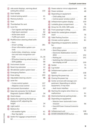
F ig. 1 Cockpit : left section
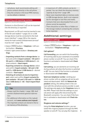
F ig. 2 Cockpit: rig ht sect ion
8
Page 11 of 409

<( a, .... N ,....
N .... 0 \0
3 a,
(!) side assist displays, warning abo ut
exiting the vehicle ..... ... .. .. .
@ Door handle
@ Cent ral locking switch ....... .. .
@ Memory buttons ........... .. .
® Vent
® Thumbwhee l for vent
(J) Lever for:
- T urn signals and h igh beams
- High beam assistant ........ .
- Active lane assist .. ..... ... . .
- Traffic jam assist ....... .. .. .
@ Mul tifunction steer ing wheel with:
- Horn
- Driver's airbag . ..... ... .. .. .
- Drive r information system con -
t rols .. .. ............. .. .. .
- Audio/v ideo, telephone, nav iga
t ion and voice recognition con-
trols . ... .... .. .... ... .. .. .
- ~ button/stee ring wheel heating
- Sh ift paddles .............. .
® Instrument cluster .... ... .. .. .
@
@
@
@
~
@
Reset trip odometer ........ .. .
W indshie ld washer system lever
Emergency flashers .... ... .. .. .
Knee a irbag ........ ..... ... . .
Adjustable steer ing column
Lever for:
- Cruise cont rol system ..... .. .
- Adaptive cruise cont rol .. ... . .
@ Instrument i llum ination ... .. .. .
@ Data link connector for On Board
Diagnostic System (OBD II) .. .. .
@ H ood release . ........... .. .. .
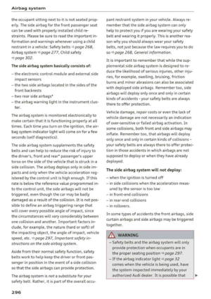
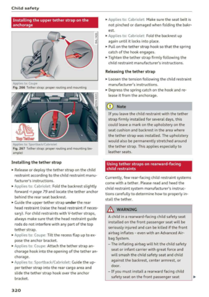
@ Button for switching the head-up
d isplay on/off, adjust ing the
height .. .. ............... .. .
@ Lig ht switch ............... .. .
@ Buttons for :
- All -weather lights .......... .
- Rear fog lights ........... .. .
@ Sw itch for luggage compartment
lid .. .. .. .. ............. .. .. .
133
41
74
6 2
62
130
121
281
13, 16
15, 16
1 5
99
10
12
67
63
293
88
107
1 13
65
24
33 1
24
61
61
61
43
Coc kpit o ve rv iew
@ Power exterior m irror adjustment
@ Power windows .............. .
@ Depend ing o n eq uipment:
- Chi ld safety lock . .. .. ..... .. .
- Central power w indow switch . .
@ Infotainment system display ... .
@ Lockable glove compa rtment ... .
@ Drives for CD, DVD, SIM cards .. .
@ Front passenge r's airbag ..... . .
@ Swi tch for cooled glove compa rt-
ment . ... .. .. ... .. .. ..... .. .
@ Valet Parking funct ion ........ .
@ Climate cont ro l system ........ .
@ Depending o n equipment, buttons
for :
- drive se lect .. .. .... .. ... .. . .
- Start/Stop system .......... .
- Electronic Stabili zation Control
(ESC) . .. .. .. .. .... . ..... .. .
- Parking aid .. .............. .
- Switching the I nfotainment sys-
tem disp lay on/off .......... .
(§) Socket ....... .. ............ .
@ Cup holder . .. ... .... . ..... .. .
@ Infotai nment system on/off
button ....... .. ............ .
@ Open ing t he power top ........ .
@ Closing the power top ......... .
@) Center armrest w it h sto rage com-
partmen t. D epending on vehicle
equipmen t, it may have:
- Audi m usic interface . ..... .. .
@ Start ing the eng ine when there is a
ma lfunction ... .. ... ....... .. .
@ E lectromechanical parking b rake
@ Depend ing o n equ ipment:
- Selector leve r (a utomat ic t ra ns-
m iss ion) .. . ... ............ .
- Gea rshif t leve r (manua l transmis
sion)
@ Infotainment unit ............ .
@ I START ENGINE STOP ! button . . .
65
48
48
48
159
76
231
281
76
51
81
138 91
152
141
159 75
76
158
54
54
237 91
94
96
158
89 ....
9
Page 12 of 409
Cockpit overv iew
@ Tips
Some the equipment listed here is only instal
led in certain mode ls or is ava ilable as an op
tion.
Instrument cluster
Instrument cluster overview
The instrument cluster is the central information center for the driver .
Fig. 3 Instrument cluster overv iew (analog)
F ig . 4 Instrument cluster overv iew (Aud i v irtual cockpit)
(!) Engine coolant temperature gauge
@ Tachometer ................. .
- With
OFF status indicator .... .
- With
READY status ind icator ..
@ Tab area ... .... ... ....... ... .
@ Central area with
10
11
12
89
89,9 1
13
- Driver information system .... .
- Indicator lights . ...... ..... .
® Status line (d isplayed on one or two
lines)
@ Speedometer/conven ience d isplay
(J) Fuel leve l ..... .. ... ......... .
® Speedometer
17
25
12
Page 13 of 409

<( a, .... N ,....
N .... 0 \0
3 a,
® Left additional display (divided in
two sections in the expanded view)
There may be additional indicator lights in the
tachometer @, the speedometer @, the status
line ® and, depending on the instrument clus
ter, above or below the central
area @.
The following pages will primarily show illustra
tions of the multi-color analog instrument clus
ter*. The display and/or position of the element
shown may vary in monochrome instrument clus
ters or in the Audi virtual cockpit*.
A WARNING
Do not assume the roads are free of ice based
on the outside temperature display. Be aware
that there may be ice on roads even when the
outside temperature is around 41 °F (+S °C)
and that ice can increase the risk of accidents.
(D Tips
-Depending on vehicle equipment, the in
strument illumination (needles and gauges)
may turn on when the lights are off and the
ignition is switched on. The illumination for
the gauges reduces automatically and even
tually turns off as brightness outside in
creases. This function reminds the driver to
turn the low beams on at the appropriate
time.
- You can select the units used for tempera
ture, speed and other measurements in the
Infotainment
system ¢ page 251.
- If your vehicle is stationary or if you are driv
ing at very low speeds, the temperature dis
played may be slightly higher than the ac
tual temperature outside due to the heat ra
diating from the engine.
- At temperatures below 41 °F (+S °C), a snowflake symbol appears in front of the
temperature display
c> &. .
Coolant temperature indicator
The coolant temperature display @¢ page 10,
fig. 3 or¢ page 10, fig. 4 only functions when
the ignition is switched on. To prevent engine
Cockpit overview
damage, please observe the following notes
about the temperature ranges.
Cold range
If only the LEDs at the bottom of the gauge turn
on, the engine has not reached operating tem
perature yet. Avoid high engine speeds , full ac
celeration and heavy engine loads.
Normal range
The engine has reached its operating tempera
ture once the LEDs up to the center of the gauge
turn on. If
the. indicator light in the instru
ment cluster display turns on, the coolant tem
perature is too high
¢ page 30.
(D Note
-Auxiliary headlights and other accessories in
front of the cooling-air intake impair the
cooling effect of the coolant. This increases
the risk of the engine overheating during
high outside temperatures and heavy en
gine load .
- The front spoiler also helps to distribute
cooling air correctly while driving. If the
spoiler is damaged, the cooling effect will
be impaired and the risk of the engine over
heating will increase. See an authorized
Audi dealer or authorized Audi Service Fa cility for assistance .
@ Tips
Diesel engines: due to the high efficiency of
these engines, the engine may not always reach operating temperature in cold outside
temperatures. This is normal and not a cause
for concern .
Engine oil temperature display and boost
indicator
Applies to : vehicles wit h engine o il temperature display/boost
indica tor
Applies to: vehicles with analog instrument cluste r
The engine oil temperature and boost indicator
are only shown in the lap timer display
¢page 111. .,._
11
Page 14 of 409

Cockpit overv iew
Engin e oil temperatur e indi cator
App lies to: ve hicles w ith Audi virtual cockpit
The engine oil temperature is only shown in the
expanded view or in the sport view
,::::, page 15.
When engine oil temperatures are low, the dis
p lay --- °F ( ---
0
() appears in the instrument clus
ter.
The engine has reached its operating tempera
ture when the engine oil temperature is between 176 °F (80 °() and 248 °F (120 °() under normal
driving conditions . The engine oil temperature
may be higher if there is heavy engine load and
h igh temperatu res outside. This is not a ca use for
concern as long as
the . ,::::, page 31 or El
,:::, page 31 indicator lights do not turn on .
Boost indicator
Applies to: ve hicles with Audi virtual cockpit
The boost indicator is only displayed in the sport
view
,:::, page 15.
The current engine load (meaning the current
boost pressure) is indicated by a bar .
Tachometer
The tachometer displays the engine speed in rev
olutions per minute (RPM).
The beginning of the red zone in the tachometer
indicates the maximum perm iss ible engine speed
for all gears once the engine has been broken in and when it is warmed up to operating tempera
ture. Before reaching this zone, you should sh ift
into the next h ighest gear, select the D/S selec
tor lever position, or remove your foot from the
accelerator pedal.
d) Note
The needle in the tachometer @,::::, page 10,
fig . 3
or ,::::, page 10, fig . 4 may only be in the
red a rea of the gauge fo r a short time or there
is a risk of engine damage. The location where
t he red zone beg ins va ries depending on the
eng ine.
12
@) For the sake of the environment
Upshifting early helps you to save fue l and re
d uces operat ing no ise .
Fuel level
The display (z)c::>page 10, fig . 3 or c::>page 10,
fig. 4
only funct ions when the ignition is switch
ed on . When the display has reached the reserve
mark, a red LED tur ns on and the
t9 indicator
li ght tur ns on
c::> page 34 . The red LED will blink
whe n the fuel level is very low .
For the tank capacity in your veh icle, refer to the
Technical
Data ,::::, page 388 .
(D Note
Never drive until the tank is comp letely emp
ty . The irregular supply of fuel t hat results
from that can cause engine misfires. Uncom
busted fue l w ill then enter the exhaust sys
tem. This ca n cause overheati ng and damage
to the ca talyt ic converte r.
Odometer
Fig. S Instrument cluste r: odomete r and reset button
Tr ip odomet er and odomet er
The trip odometer shows the distance driven
s ince it was last reset.
It can be used to measure
shor t dista nces.
The trip odometer can be reset to zero by press
i ng the
@J reset button.
The odometer shows the total distance that the
vehicle has been driven.
llJI,
Page 15 of 409

Malfunction indicator
If there is a malfunction in the instrument clus
ter,
DEF wi ll appear in the trip odometer display.
Have the malfunction corrected as soon as possi
b le.
@ Tips
The units of measurement can be set in the
I nfotainment system
Q page 251.
Multifunction steering
wheel plus
Operating
Applies to: vehicles with multifunction steering wheel plus
You can use the multifunction steering wheel
plus to operate the driver information system
and the
MMI functions, adjust the volume and
switch the voice recognition system on and off.
Fig. 6 Driver informat ion system d isplay
Fig. 7 left s ide of multifunc tion stee ring wheel p lus
Requirement: the ign ition must be switched on.
The driver information system contains multiple
~ tabs©¢ fig. 6 that display various information
~ @.
N ..... 0
'° ~ co
Cockpit overview
The following tabs are available, depending on
vehicle equipment:
First tab Vehicle (on-board computer)
Q page 17
Second Messages
tabal
Third tab Radio
Media
¢ page 18
Fourth tab Telephone* ¢ page 19
Fift h tab Navigation* ¢ page
20
Map* ¢page21
a) Thi s ta b is on ly vis ib le when t here is at leas t one indicato r
li ght o r m essag e disp layed .
@ Button I <1 1> I
-Switching tabs: press the ~ button repeated
ly until the desired tab is shown (for example ,
Radio) .
@IVIEWI button
Switching views or reducing the display
Q page 15.
@ Button [2l
Return to functions at higher levels
@ Control buttons 12) and [g
Open/close the selection menu or options menu
Qpage 14.
(z) Left thumbwheel
- Selecting a function in a menu/list:
turn the
left thumbwheel to the desired function (for
example, selecting a frequency) .
-Confirming a selection: press the left thumb
wheel
(J) ¢ fig . 7.
- Zooming in/out on the map: when a map is
displayed, turn the left thumbwheel to zoom in
and out on the map.
13
Page 16 of 409
Cockpit overview
Control buttons
Applies to: vehicles w ith mu ltifunct ion steering wheel p lus
I rM
' t M' ...
F ig . 8 Select ion menu an d opt io ns m en u
Left control button
- Opening/closing the selection menu :
press the
respective left control button on the steering
wheel¢ fig. 8. You can select and confirm a
function in the selection menu using the left
thumbwheel (for example , selecting a frequen
cy band).
Right control button
- Opening/closing the options menu :
press the
respective right control button on the steering
wheel¢ fig. 8. You can change any context-de
pendent functions and settings using the left
thumbwheel (for example, additional station
in format ion).
(D Tips
The ava ilability of a se lection menu or options
menu depends on the function that is select
ed.
14