2018 Alfa Romeo Stelvio ESP
[x] Cancel search: ESPPage 189 of 276

IN CASE OF EMERGENCY
Have a flat tire or a burnt-out bulb?
At times, a problem such as these may
interfere with your driving experience.
The section on emergencies can help you
to deal with critical situations
independently.
In an emergency, we recommend that you
call the phone number found in the
Warranty Book.
You may also consider contacting an
authorized dealer.HAZARD WARNING LIGHTS.....188
BULB REPLACEMENT .........188
FUSES .................. .193
TIRE SERVICE KIT ............198
JUMP STARTING ............201
ENGINE OVERHEATING ........203
TOWING A DISABLED VEHICLE . . .204
TOW EYES ............... .206
ENHANCED ACCIDENT RESPONSE
SYSTEM (EARS) .............207
EVENT DATA RECORDER (EDR) . . .207
187
Page 190 of 276

HAZARD WARNING LIGHTS
The Hazard Warning flasher switch is
located in the switch bank below the
radio screen.Push the switch once to
turn the hazard warning
flasher on. When the
switch is activated, all
directional turn signals
will flash on and off to
warn oncoming traffic
of an emergency. Push the switch a
second time to turn the hazard warning
flashers off.
This is an emergency warning system and
it should not be used when the vehicle is
in motion. Use it when your vehicle is
disabled and is creating a safety hazard
for other motorists.
When you must leave the vehicle to seek
assistance, the hazard warning flashers
will continue to operate even though the
ignition is cycled to STOP.
Caution!
Prolonged use of the hazard warning
flashers may discharge the vehicle’s battery.
Panic Brake Assist (PBA) System
The PBA system is designed to improve
the vehicle’s braking capacity during
emergency braking.
For further details about the Panic Brake
Assist System, refer to the "Active
Safety Systems" section in the "Safety"
chapter.
BULB REPLACEMENT
General Instructions
Before replacing a bulb, check the
contacts for oxidation.
Replace blown bulbs with others of the
same type and power.
After replacing a headlight bulb,
always check its alignment.
When a light is not working, check that
the corresponding fuse is intact before
changing the bulb. For the location of
fuses, refer to “Fuses” in this chapter.
Note: In some particular climate
conditions, such as low temperature,
humidity, or after washing the vehicle, a
thin condensation layer may form on the
internal surfaces of the front and rear
headlights. This condensation will
disappear after switching on the
headlights.
0403132206USHazard Warning Switch
188
IN CASE OF EMERGENCY
Page 197 of 276

may result in serious personal injury, fire
and/or property damage.
Before replacing a fuse, make sure that
the ignition is off and that all the other
services are switched off and/or
disengaged.
If the replaced fuse blows again, contact
an authorized dealer.
If a general protection fuse for safety
systems (air bag system, braking system),
power unit systems (engine system,
transmission system) or steering system
blows, contact an authorized dealer.
Fuse Location
The fuses, which can be replaced by the
user, are grouped in two boxes below the
passenger side foot board and inside the
luggage compartment.
Control Unit Under Passenger Side
Footboard
To access the fuses, proceed as follows:
1. Lift the upper end of the footboard on
the passenger side, pulling to release the
two buttons. Release Buttons On Footboard
1 — Footboard
2. Unscrewing the two hooks, remove
the panel pulling downward.
Release Hooks On Footboard
2 — Panel
The fuses are freely accessible on the
control unit.
After replacing the fuse, make sure that
panel and footboard are correctly locked.
Luggage Compartment Fuse Box
To access the fuses, proceed as follows:
1. Lift the luggage compartment cover.
2. Remove the control unit cover.
The fuses are freely accessible on the
control unit.
The number identifying the electrical
component corresponding to each fuse is
shown on the cover.
After replacing a fuse, make sure that
you have closed the cover correctly.
08036V0010EM
08036V0011EM
08036V0014EMControl Unit
195
Page 201 of 276

Inflation Procedure
Warning!
Do not attempt to seal a tire on the side of
the vehicle closest to traffic. Pull far enough
off the road to avoid the danger of being hit
when using the Tire Service Kit.
Do not use Tire Service Kit or drive the
vehicle under the following circumstances:
If the puncture in the tire tread is
approximately 1/4 inch (6 mm) or larger.
If the tire has any sidewall damage.
If the tire has any damage from driving
with extremely low tire pressure.
If the tire has any damage from driving on
a flat tire.
If the wheel has any damage.
If you are unsure of the condition of the
tire or the wheel.
Keep Tire Service Kit away from open
flames or heat sources.
A loose Tire Service Kit thrown forward in
a collision or hard stop could endanger the
occupants of the vehicle. Always stow the
Tire Service Kit in the place provided. Failure
to follow these warnings can result in
injuries that are serious or fatal to you, your
passengers, and others around you.
Take care not to allow the contents of Tire
Service Kit to come in contact with hair,
eyes, or clothing. Tire Service Kit sealant is
harmful if inhaled, swallowed, or absorbed through the skin. It causes skin, eye, and
respiratory irritation. Flush immediately
with plenty of water if there is any contact
with eyes or skin. Change clothing as soon
as possible, if there is any contact with
clothing.
Tire Service Kit Sealant solution contains
latex. In case of an allergic reaction or rash,
consult a physician immediately. Keep Tire
Service Kit out of reach of children. If
swallowed, rinse mouth immediately with
plenty of water and drink plenty of water.
Do not induce vomiting! Consult a physician
immediately.
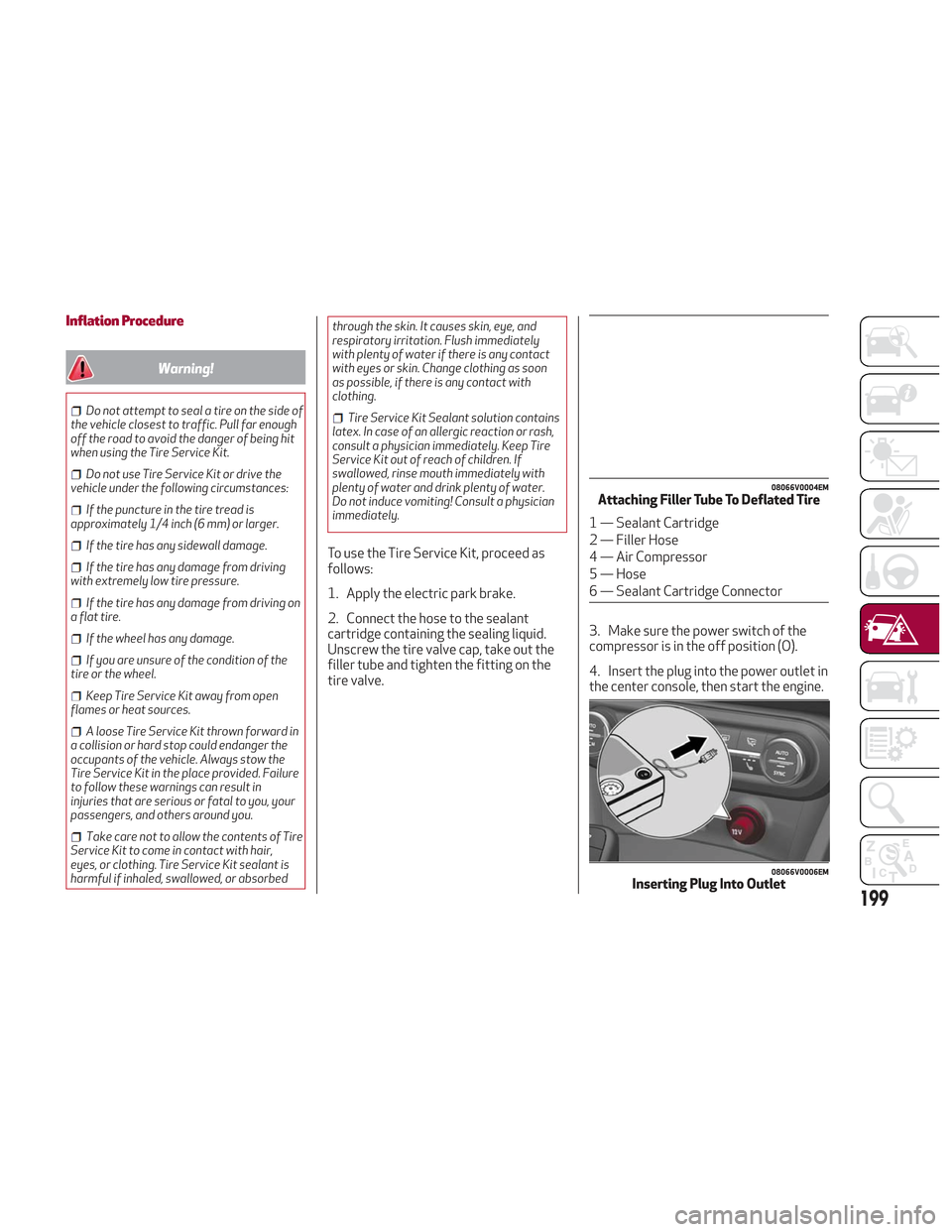
To use the Tire Service Kit, proceed as
follows:
1. Apply the electric park brake.
2. Connect the hose to the sealant
cartridge containing the sealing liquid.
Unscrew the tire valve cap, take out the
filler tube and tighten the fitting on the
tire valve. 3. Make sure the power switch of the
compressor is in the off position (O).
4. Insert the plug into the power outlet in
the center console, then start the engine.
08066V0004EMAttaching Filler Tube To Deflated Tire
1 — Sealant Cartridge
2 — Filler Hose
4 — Air Compressor
5 — Hose
6 — Sealant Cartridge Connector
08066V0006EMInserting Plug Into Outlet
199
Page 209 of 276

ENHANCED ACCIDENT
RESPONSE SYSTEM (EARS)
This vehicle is equipped with an
Enhanced Accident Response System.
Please refer to “Occupant Restraint
Systems” in “Safety” for further
information on the Enhanced Accident
Response System (EARS) function.
EVENT DATA RECORDER (EDR)
This vehicle is equipped with an Event
Data Recorder (EDR). The main purpose
of an EDR is to record data that will
assist in understanding how a vehicle’s
systems performed under certain crash
or near crash-like situations, such as an
air bag deployment or hitting a road
obstacle.
Please refer to “Occupant Restraint
Systems” in “Safety” for further
information on the Event Data Recorder
(EDR).
207
Page 216 of 276

Thousands of miles10
20 30
40 50
60
70
80
90
100
110
120
130
140
150
Years123456789101112131415
Thousands of kilometers16
32 48
64 80
96
112
128
144
160
176
192
208
224
240
Change the brake fluid.(5)
Replace the cabin air filter(6)o ● o● o● o● o● o● o● o
Spark plug replacement.
*●●●●●
(5) The brake fluid replacement has to be done every two years, irrespective of the mileage.
(6) If the vehicle is used in dusty areas, this cleaner must be replaced every 10,000 miles (16,000 km).
* The spark plug change interval is mileage-based only. Yearly intervals do not apply.
(o) Recommended operations
(●) Mandatory operations
Warning!
You can be badly injured working on or around a motor vehicle. Do only service work for which you have the knowledge and the right equipment.
If you have any doubt about your ability to perform a service job, take your vehicle to a competent mechanic.
Failure to properly inspect and maintain your vehicle could result in a component malfunction and effect vehicle handling and performance.
This could cause an accident.
214
SERVICING AND MAINTENANCE
Page 218 of 276

Engine Oil
The engine oil level can be seen on the
instrument cluster display every time the
engine is started, or on the Information
and Entertainment system display by
activating on the main menu (MENU
button) the following functions in
sequence:
1. “Apps”
2. “My Car”
3. “Oil Level”
Check on the display using the 6 notches
that the oil level is between the MIN and
MAX level: 1 notch MIN level, 6 notches
MAX level.
If the oil level is close to or below the MIN
mark, add oil gradually through the filler,
(refer to “Top-Up And Oil Level Indication
Update On Display” in this section)
considering that each notch shown on the
display corresponds to approximately
8.8floz(250ml).
Caution!
Make sure not to add too much oil when
topping off the engine. Engine oil in excess
may damage the engine. Have the vehicle
checked. Never exceed the MAX level when
topping off engine oil.
Caution!
The oil level is not refreshed immediately on
the display after topping off. Consequently,
wait for the oil level to be refreshed on the
display and follow the procedure below.
Note:Always reinstall the oil cap and
tighten to proper torque whenever it is
removed to add oil to engine. Never run
the engine with cap removed this could
cause oil to leak from engine.
Top-Up And Oil Level Indication Update
On Display
If a engine oil top-off is needed, in order
to ensure the correct indication of the oil
level on the display, leave the vehicle on
flat ground with the engine running for
approximately five minutes (temperature
higher than 176°F (80°C)) and shut the
engine off. Then, start the engine again,
and idle it for about five minutes.
Note: If you have added the specified
amount of oil and the indicator is not
reading “Full”, please contact an
authorized dealer.
Warning!
If the engine oil is being topped up, wait for
the engine to cool down before loosening the
filler cap, particularly for vehicles with
aluminium cap (if equipped). WARNING: risk
of burns!
Caution!
The oil level must never exceed the MAX
mark.
If the MAX mark is exceeded MAX (last
notch on the right turns red) after the fill-up,
go to an authorized dealer as soon as
possible to have the oil in excess removed.
Do not add oil with specifications
different from those of the oil already in the
engine.
Used engine oil and oil filters contain
substances which are harmful to the
environment. To change the oil and filters,
we advise you to contact an authorized
dealer.
Engine Coolant Fluid
If the level is too low, unscrew the cap of
the reservoir and add the fluid described
in the "Technical Specifications" chapter.
216
SERVICING AND MAINTENANCE
Page 229 of 276

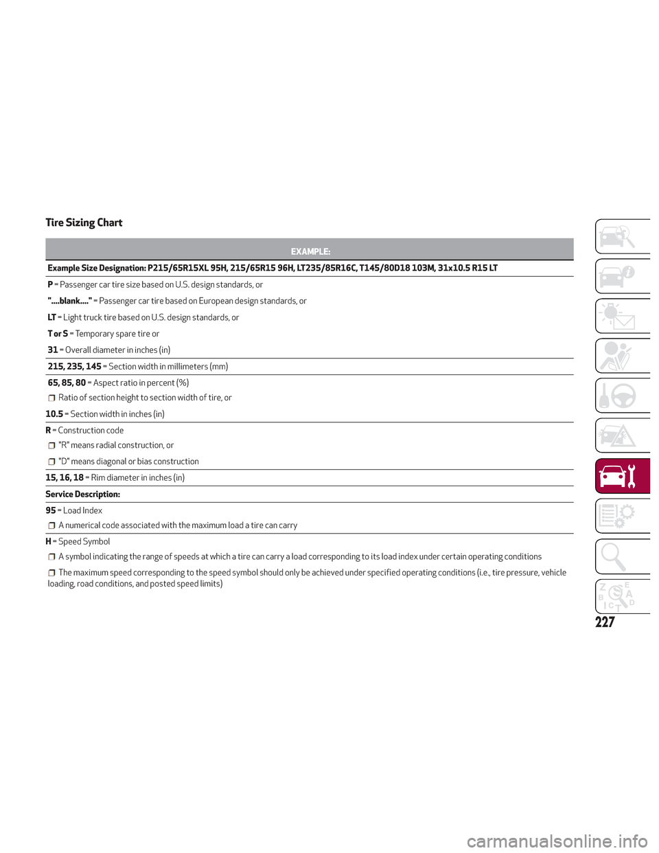
Tire Sizing Chart
EXAMPLE:
Example Size Designation: P215/65R15XL 95H, 215/65R15 96H, LT235/85R16C, T145/80D18 103M, 31x10.5 R15 LT
P =
Passenger car tire size based on U.S. design standards, or
"....blank...." = Passenger car tire based on European design standards, or
LT = Light truck tire based on U.S. design standards, or
TorS = Temporary spare tire or
31 = Overall diameter in inches (in)
215, 235, 145 = Section width in millimeters (mm)
65, 85, 80 = Aspect ratio in percent (%)
Ratio of section height to section width of tire, or
10.5= Section width in inches (in)
R = Construction code
"R" means radial construction, or
"D" means diagonal or bias construction
15, 16, 18 = Rim diameter in inches (in)
Service Description:
95 = Load Index
A numerical code associated with the maximum load a tire can carry
H= Speed Symbol
A symbol indicating the range of speeds at which a tire can carry a load corresponding to its load index under certain operating conditions
The maximum speed corresponding to the speed symbol should only be achieved under specified operating conditions (i.e., tire pressure, vehicle
loading, road conditions, and posted speed limits)
227