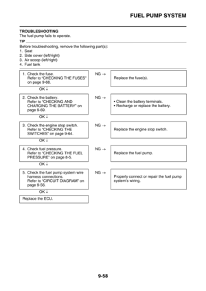
Page 321 of 432

WATER PUMP
7-6
EAS2GBB333REMOVING THE OIL SEAL
TIP
• Remove the oil seal when the coolant level
changes frequently more than usual, coolant
has discolored, or engine oil has become
milky.
• Do not use the removed oil seal.
1. Remove:
• Oil seals “1”
EAS2GBB334CHECKING THE WATER PUMP
1. Check:
• Water pump housing cover
• Impeller shaft
Cracks/damage/wear Replace.
EAS2GBB335CHECKING THE BEARING
1. Check:
• Bearing
Rotate the inner race with your finger.
Rough spot/seizure Replace.
EAS2GBB336INSTALLING THE OIL SEAL
1. Install:
• Oil seals “1”
TIP
• Apply the lithium-soap-based grease on the
oil seal lip.
• Install the oil seal with its manufacture’s
marks or numbers facing the right crankcase
cover “2”.2. Install:
• Bearing “1”
TIP
Install the bearing by pressing its outer race
parallel.
EAS2GBB337ASSEMBLING THE WATER PUMP
1. Install:
• Impeller shaft assembly “1”
• Washer “2”
•Pin “3”
• Gear “4”
• Collar “5”
• Circlip “6”
TIP
• Take care so that the oil seal lip is not dam-
aged or the spring does not slip off its posi-
tion.
• Apply the lithium-soap-based grease on the
impeller shaft.
1 1
New
1 1New
New
LS
LS2
New
1
2
52346
New
LS
Page 322 of 432
WATER PUMP
7-7
2. Install:
• Dowel pin “1”
• Gasket “2”
3. Install:
• Water pump housing “1”
• Water pump housing bolt “2”
• Washer “3”
• Coolant drain bolt “4”Water pump housing bolt
10 Nm (1.0 m·kgf, 7.2 ft·lbf)
Coolant drain bolt
10 Nm (1.0 m·kgf, 7.2 ft·lbf)
New
21
1New
T R..
New
T R..
2
2
43 1
New
Page 323 of 432

8
FUEL SYSTEM
FUEL TANK...................................................................................................... 8-1
REMOVING THE FUEL TANK ................................................................... 8-3
REMOVING THE FUEL PUMP .................................................................. 8-3
CHECKING THE FUEL PUMP BODY........................................................ 8-3
INSTALLING THE FUEL PUMP ................................................................. 8-3
REMOVING THE FUEL SENDER.............................................................. 8-4
CHECKING THE FUEL SENDER .............................................................. 8-4
INSTALLING THE FUEL SENDER ............................................................ 8-4
INSTALLING THE FUEL TANK.................................................................. 8-4
CHECKING THE FUEL PRESSURE ......................................................... 8-5
CHECKING THE DAMPER ........................................................................ 8-6
CHECKING AND REPLACING THE PROTECTOR .................................. 8-6
THROTTLE BODY............................................................................................ 8-7
CHECKING THE INJECTOR ................................................................... 8-10
CHECKING THE THROTTLE BODY ....................................................... 8-10
CHECKING THE THROTTLE BODY JOINT ............................................ 8-10
ADJUSTING THE THROTTLE POSITION SENSOR............................... 8-11
Page 324 of 432

FUEL TANK
8-1
EAS2GBB338
TIP
This section is intended for those who have basic knowledge and skill concerning the servicing of
Yamaha motorcycles (e.g., Yamaha dealers, service engineers, etc.). Those who have little knowl-
edge and skill concerning servicing are requested not to undertake inspection, adjustment, disas-
sembly, or reassembly only by reference to this manual. It may lead to servicing trouble and
mechanical damage.
EAS2GBB339
FUEL TANK
Removing the fuel tank
Order Part name Q’ty Remarks
Seat Refer to “GENERAL CHASSIS” on page 5-1.
Side cover (left/right)
Air scoop (left/right)
1 Fuel pump coupler 1 Disconnect.
2 Fuel hose 1 Disconnect.
3Fuel tank 1
4 Fuel pump bracket 1
5 Fuel pump 1
6 Fuel pump gasket 1
7 Fuel sender 1
4(6) (2)
(2) (2)(2)2
5
6
3
1
New
4.0 Nm (0.40 m kgf, 2.9 ft Ibf)T.R.
7 Nm (0.7 m kgf, 5.1 ft Ibf)T.R.
9 Nm (0.9 m kgf, 6.5 ft Ibf)T.R.
4.0 Nm (0.40 m kgf, 2.9 ft Ibf)T.R.
7
Page 325 of 432
FUEL TANK
8-2
For installation, reverse the removal proce-
dure.
Removing the fuel tank
Order Part name Q’ty Remarks
4(6) (2)
(2) (2)(2)2
5
6
3
1
New
4.0 Nm (0.40 m kgf, 2.9 ft Ibf)T.R.
7 Nm (0.7 m kgf, 5.1 ft Ibf)T.R.
9 Nm (0.9 m kgf, 6.5 ft Ibf)T.R.
4.0 Nm (0.40 m kgf, 2.9 ft Ibf)T.R.
7
Page 326 of 432

FUEL TANK
8-3
EAS2GBB340REMOVING THE FUEL TANK
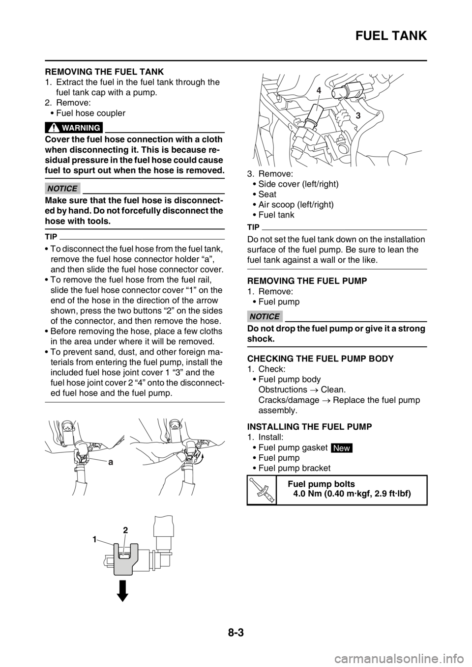
1. Extract the fuel in the fuel tank through the
fuel tank cap with a pump.
2. Remove:
• Fuel hose coupler
EWA
WARNING
Cover the fuel hose connection with a cloth
when disconnecting it. This is because re-
sidual pressure in the fuel hose could cause
fuel to spurt out when the hose is removed.
ECA
NOTICE
Make sure that the fuel hose is disconnect-
ed by hand. Do not forcefully disconnect the
hose with tools.
TIP
• To disconnect the fuel hose from the fuel tank,
remove the fuel hose connector holder “a”,
and then slide the fuel hose connector cover.
• To remove the fuel hose from the fuel rail,
slide the fuel hose connector cover “1” on the
end of the hose in the direction of the arrow
shown, press the two buttons “2” on the sides
of the connector, and then remove the hose.
• Before removing the hose, place a few cloths
in the area under where it will be removed.
• To prevent sand, dust, and other foreign ma-
terials from entering the fuel pump, install the
included fuel hose joint cover 1 “3” and the
fuel hose joint cover 2 “4” onto the disconnect-
ed fuel hose and the fuel pump.3. Remove:
• Side cover (left/right)
• Seat
• Air scoop (left/right)
• Fuel tank
TIP
Do not set the fuel tank down on the installation
surface of the fuel pump. Be sure to lean the
fuel tank against a wall or the like.
EAS2GBB341REMOVING THE FUEL PUMP
1. Remove:
• Fuel pump
ECA
NOTICE
Do not drop the fuel pump or give it a strong
shock.
EAS2GBB342CHECKING THE FUEL PUMP BODY
1. Check:
• Fuel pump body
Obstructions Clean.
Cracks/damage Replace the fuel pump
assembly.
EAS2GBB343INSTALLING THE FUEL PUMP
1. Install:
• Fuel pump gasket
• Fuel pump
• Fuel pump bracket
a
1
2
Fuel pump bolts
4.0 Nm (0.40 m·kgf, 2.9 ft·lbf)
3 4
New
T R..
Page 327 of 432

FUEL TANK
8-4
TIP
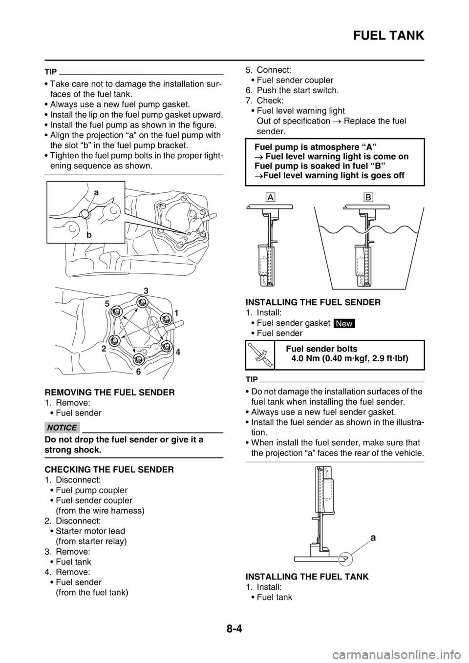
• Take care not to damage the installation sur-
faces of the fuel tank.
• Always use a new fuel pump gasket.
• Install the lip on the fuel pump gasket upward.
• Install the fuel pump as shown in the figure.
• Align the projection “a” on the fuel pump with
the slot “b” in the fuel pump bracket.
• Tighten the fuel pump bolts in the proper tight-
ening sequence as shown.
EAS2GBB344REMOVING THE FUEL SENDER
1. Remove:
• Fuel sender
ECA
NOTICE
Do not drop the fuel sender or give it a
strong shock.
EAS2GBB345CHECKING THE FUEL SENDER
1. Disconnect:
• Fuel pump coupler
• Fuel sender coupler
(from the wire harness)
2. Disconnect:
• Starter motor lead
(from starter relay)
3. Remove:
• Fuel tank
4. Remove:
• Fuel sender
(from the fuel tank)5. Connect:
• Fuel sender coupler
6. Push the start switch.
7. Check:
• Fuel level warning light
Out of specification Replace the fuel
sender.
EAS2GBB346INSTALLING THE FUEL SENDER
1. Install:
• Fuel sender gasket
• Fuel sender
TIP
• Do not damage the installation surfaces of the
fuel tank when installing the fuel sender.
• Always use a new fuel sender gasket.
• Install the fuel sender as shown in the illustra-
tion.
• When install the fuel sender, make sure that
the projection “a” faces the rear of the vehicle.
EAS2GBB347INSTALLING THE FUEL TANK
1. Install:
• Fuel tank
a
b
4 1
2
6
53
Fuel pump is atmosphere “A”
Fuel level warning light is come on
Fuel pump is soaked in fuel “B”
Fuel level warning light is goes off
Fuel sender bolts
4.0 Nm (0.40 m·kgf, 2.9 ft·lbf)
New
T R..
a
Page 328 of 432

FUEL TANK
8-5
2. Connect:
• Fuel hose
ECA
NOTICE
• Connect the fuel hose securely, and check
that the orientation of the installed fuel
hose holder is correct.
• Take care not to kink or pinch the fuel
hose.
TIP
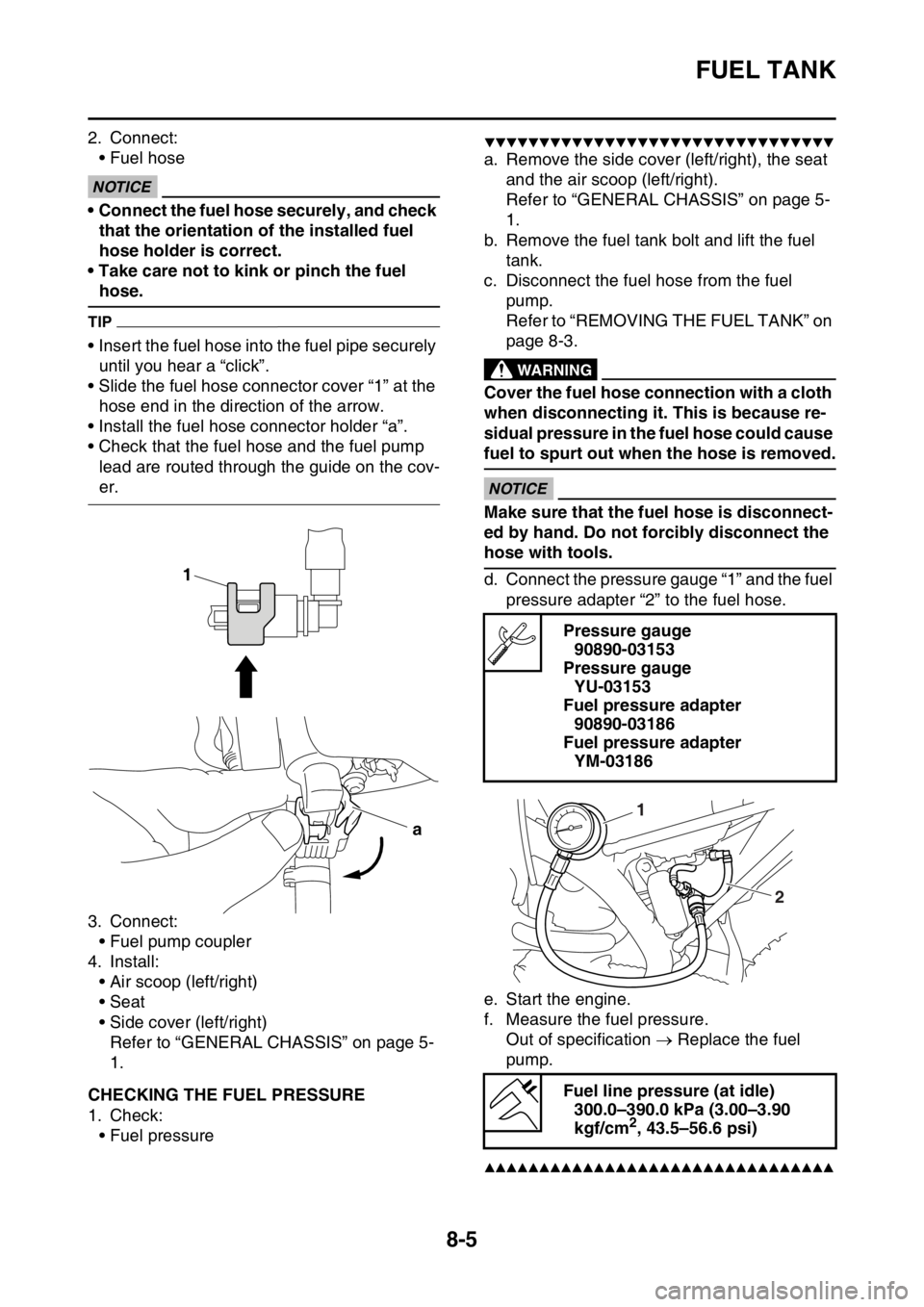
• Insert the fuel hose into the fuel pipe securely
until you hear a “click”.
• Slide the fuel hose connector cover “1” at the
hose end in the direction of the arrow.
• Install the fuel hose connector holder “a”.
• Check that the fuel hose and the fuel pump
lead are routed through the guide on the cov-
er.
3. Connect:
• Fuel pump coupler
4. Install:
• Air scoop (left/right)
• Seat
• Side cover (left/right)
Refer to “GENERAL CHASSIS” on page 5-
1.
EAS2GBB348CHECKING THE FUEL PRESSURE
1. Check:
• Fuel pressure
▼▼▼▼▼▼▼▼▼▼▼▼▼▼▼▼▼▼▼▼▼▼▼▼▼▼▼▼▼▼▼▼
a. Remove the side cover (left/right), the seat
and the air scoop (left/right).
Refer to “GENERAL CHASSIS” on page 5-
1.
b. Remove the fuel tank bolt and lift the fuel
tank.
c. Disconnect the fuel hose from the fuel
pump.
Refer to “REMOVING THE FUEL TANK” on
page 8-3.
EWA
WARNING
Cover the fuel hose connection with a cloth
when disconnecting it. This is because re-
sidual pressure in the fuel hose could cause
fuel to spurt out when the hose is removed.
ECA
NOTICE
Make sure that the fuel hose is disconnect-
ed by hand. Do not forcibly disconnect the
hose with tools.
d. Connect the pressure gauge “1” and the fuel
pressure adapter “2” to the fuel hose.
e. Start the engine.
f. Measure the fuel pressure.
Out of specification Replace the fuel
pump.
▲▲▲▲▲▲▲▲▲▲▲▲▲▲▲▲▲▲▲▲▲▲▲▲▲▲▲▲▲▲▲▲
1
a
Pressure gauge
90890-03153
Pressure gauge
YU-03153
Fuel pressure adapter
90890-03186
Fuel pressure adapter
YM-03186
Fuel line pressure (at idle)
300.0–390.0 kPa (3.00–3.90
kgf/cm
2, 43.5–56.6 psi)
1
2