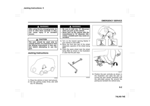
Page 209 of 336

7-18
INSPECTION AND MAINTENANCE
74LH0-74E
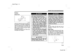
Check that the steering wheel turns easily
and smoothly without rattling by turning it
all the way to the right and to the left while
driving very slowly in an open area. If the
amount of free play is outside the specifi-
cation or you find anything else to be
wrong, an inspection must be performed
by your MARUTI SUZUKI dealer.Tires
74LHT0704
The front and rear tire pressure specifica-
tions for your vehicle are listed on the Tire
Information Label. Both the front and rear
tires should have the specified tire pres-
sure.Tire InspectionInspect your vehicle’s tires at least once a
month by performing the following checks:
1) Measure the air pressure with a tire
gauge. Adjust the pressure if neces-
sary. Remember to check the spare
tire, too.
54G136
(1) Tread wear indicator
(2) Indicator location mark2) Check that the depth of the tread
groove is more than 1.6 mm (0.06 in.).
To help you check this, the tires have
molded-in tread wear indicators in the
grooves. When the indicators appear
on the tread surface, the remaining
depth of the tread is 1.6 mm (0.06 in.)
or less and the tire should be replaced.
3) Check for abnormal wear, cracks and
damage. Any tires with cracks or other
damage should be replaced. If any tires
show abnormal wear, have them
inspected by your MARUTI SUZUKI
dealer.
4) Check for loose wheel nuts.
5) Check that there are no nails, stones or
other objects sticking into the tires.
EXAMPLE
WA R N I N G
Air pressures should be checked
when the tires are cold or you may
get inaccurate readings.
Check the inflation pressure from
time to time while inflating the tire
gradually, until the specified pres-
sure is obtained.
Never underinflate or overinflate
the tires.
Underinflation can cause unusual
handling characteristics or can
cause the rim to slip on the tire
bead, resulting in an accident or
damage to the tire or rim.
Overinflation can cause the tire to
burst, resulting in personal injury.
Overinflation can also cause
unusual handling characteristics
which may result in an accident.EXAMPLE
CAUTION
Hitting curbs and running over rocks
can damage tires and affect wheel
alignment. Be sure to have tires and
wheel alignment checked periodi-
cally by your MARUTI SUZUKI dealer.
Brakes: 6
Page 210 of 336

7-19INSPECTION AND MAINTENANCE
74LH0-74E
Tire Rotation
60G-09-019E
To avoid uneven wear of your tires and to
prolong their life, rotate the tires as illus-
trated. Tires should be rotated as men-
tioned in periodic maintenance schedule.
After rotation, adjust front and rear tire
pressures to the specification listed on
your vehicle’s Tire Inflation Pressure Label.
Wheel Balancing
If the vehicle vibrates abnormally on
smooth road, have the wheel balanced at
Maruti Suzuki Authorized Workshop.
Wheel Alignment
In case of abnormal tire wear or pulling
towards one side, have the wheel aligned
at Maruti Suzuki Authorized Workshop.Tubeless Tires (If equipped)
The vehicle is equipped with Tubeless
Tires. In tubeless tire, a thin layer of butyl
rubber is used for lining the inside of the
tubeless tire. This layer is to prevent air
loss and fulfilling the purpose of tube. The
air pressure is maintained by the sealing
between tire bead and wheel rim. Tubelesstires are having advantage of slow air loss
and preventing sudden deflation while driv-
ing.
Care and maintenance tips for tubeless
tires
1) Always maintain recommended inflation
pressure. Driving continuously at low
inflation pressure can lead to tire dam-
age.
2) In case any leakage is found, check for
any nail penetration/valve core dam-
age or rim bent. Damaged wheel must
not be used.
3) In case tire has run at low pressure, it
must be inspected for any defect.
4) Whenever new tire is fitted, replace the
valve.
5) If continuous high speed driving is
required, increase tires pressure by 5
psi over recommended inflation pres-
sure.
6) Never run the tire beyond TWI (Tread
wear indicator). The tire is recom-
mended to be replaced when the
remaining tread has worn to this point.
The indicators are spaced across the
tread around the tire marked by a trian-
gular symbol (TWI).
7) Always prefer tubeless tire mounting
machine. In case of manual mounting-
tire/wheel rim damage may occur.
8) In case of any problem, please get in
touch with MARUTI SUZUKI Authorized
workshop.
WA R N I N G
Your MARUTI SUZUKI is equipped
with tires which are all the same
type and size. This is important to
ensure proper steering and han-
dling of the vehicle. Never mix tires
of different size or type on the four
wheels of your vehicle. The size
and type of tires used should be
only those approved by MARUTI
SUZUKI as standard or optional
equipment for your vehicle.
Replacing the wheels and tires
equipped on your vehicle with cer-
tain combinations of after-market
wheels and tires can significantly
change the steering and handling
characteristics of your vehicle.
Therefore, use only those wheel
and tire combinations approved by
MARUTI SUZUKI as standard or
optional equipment for your vehi-
cle.
NOTICE
Replacing the original tires with tires
of a different size may result in false
speedometer or odometer readings.
Brakes: 6
Steering: 6
Power Steering: 6
Page 211 of 336

7-20
INSPECTION AND MAINTENANCE
74LH0-74E
Temporary Spare Tire (if equipped)Your vehicle comes equipped with the tem-
porary spare tire. It is only intended for
temporary emergency use, until the con-
ventional tire can be repaired or replaced.
The inflation pressure of the temporary
spare tire should be checked at least
monthly. At the same time, check that the
tire is stored securely. If it is not, tighten it.
Note that two or more temporary spare
tires should not be used on one vehicle
simultaneously.
BatteryPetrol
54G118
WA R N I N G
The temporary spare tire and wheel
are intended for temporary emergency
use only. Continuous use of this spare
can result in tire failure and loss of
control. Always observe these precau-
tions when using this spare: Your vehicle will handle differently
with this temporary spare.
Do not exceed 80 km/h speed (only
vehicle with 185/65R15 tire).
Replace this spare with a standard
tire and wheel as soon as possible.
Use of this spare will reduce
ground clearance.
Set the specified tire pressure indi-
cated on the tire information label
located on the driver’s door lock
pillar.
Do not use tire chains on the tem-
porary spare. If you must use tire
chains, rearrange the wheels so
standard tires and wheels are fitted
to the front axle.
The temporary spare tire has a
much shorter tread life than the
conventional tires on your vehicle.
Replace the tire as soon as the
tread wear indicator appears.
When replacing the temporary
spare tire, use a replacement tire
with the exact same size and con-
struction.
WA R N I N G
Batteries produce flammable
hydrogen gas. Keep flames and
sparks away from the battery or an
explosion may occur. Never smoke
when working in the vicinity of the
battery.
When checking or servicing the
battery, disconnect the negative
cable. Be careful not to cause a
short circuit by allowing metal
objects to contact the battery posts
and the vehicle at the same time.
To avoid harm to yourself or dam-
age to your vehicle or battery, fol-
low the jump starting instructions
in the “EMERGENCY SERVICE”
section of this manual if it is neces-
sary to jump start your vehicle.EXAMPLE-1
Clutch Pedal: 6
Tires: 6
Page 212 of 336

7-21INSPECTION AND MAINTENANCE
74LH0-74E
Diesel
The level of the battery solution must be
kept between the “Max” and the “Min” level
lines at all times. If the level is found to be
below the “Min” level line, add distilled
water to bring level between “Max” and
“Min”. You should, however, periodically
check the battery, battery terminals and
battery hold-down bracket for corrosion.
Remove corrosion using a stiff brush and
ammonia mixed with water, or baking soda
mixed with water. After removing corrosion,
rinse with clean water.
If your vehicle is not going to be driven for
a month or longer, disconnect the cable
from the negative terminal of the battery to
help prevent discharge..Replacement of the battery
TYPE 1
51KM038
TYPE 2
51KM039
To remove the battery:
1) Disconnect the negative cable (1).
2) Disconnect the positive cable (2).
For Type 1
3) Remove the retainer nuts (3) and
remove the retainer (4).
For Type 2
3) Remove the bracket bolt (3) and
remove the bracket (4).
4) Remove the battery.
To install the battery:
1) Install the battery in the reverse order of
removal.
2) Tighten the retainer nuts and battery
cables securely.
NOTE:
When the battery is disconnected, some of
the vehicle’s function will be initialized and/
or deactivated.
These function are required to reset after
the battery is reconnected.
EXAMPLE-2
Max
Min
EXAMPLE
(1)
(2)
(3)
(4)
EXAMPLE
(1)
(2)
(3)
(4)
EXAMPLE
NOTICE
Ensure that battery should not be
removed without cover assembly.
When the battery is reassembled
into the vehicle, kindly ensure that
battery cover is also installed along
with battery.
Tires: 6
Page 213 of 336

7-22
INSPECTION AND MAINTENANCE
74LH0-74E
FusesYour vehicle has three types of fuses, as
described below:
Main fuse
The main fuse takes current directly from
the battery.
Primary fuses
These fuses are between the main fuse
and individual fuses, and are for electrical
load groups.
Individual fuses
These fuses are for individual electrical cir-
cuits.Fuses in the Engine Compartment
74LHT0715
(5)
(3) (4)
(2)(1)(5)
(4)
(3)
(2)(1) (6)
MAIN FUSE / PRIMARY FUSE
(1)
100 A
FL1 (GAS)
120 A
FL1 (DIESEL)
(2)
100 A
FL2
(3)
100 A
FL3
(4) 50 A FL4
(5) 80 A FL5
(6)
100 A
FL6 (DIESEL)
(7) 50 A Ignition switch -2
(8) 7.5 A ECM
(9) 15 A AT
(10) 20 A F/P (DIESEL)
(11) 10 A Air compressor
(7)
(8)(9)
(10)
(11)
(12)
(13)
(14)
(15)
(16)(17)
(18)
(20) (19)
(21)
(22)
(23)
(25) (24)
(26)
(27)(28)
(29)
(30)
(31)
(12) 15 A FI (PETROL)
(13) 30 A FI (DIESEL)
(14) 60 A Power steering
(15) 30 A Radiator fan
(16) 40 A ABS 1
(17) 30 A Blower fan
(18) 30 A Starting motor
(19) 30 A T/M Pump (AGS)
(20) 30 A Backup
(21) 10 A T/M (AGS)
(22) 15 A Head light (Left)
(23) 25 A ABS control module
(24) 15 A Head light (Right)
(25) 20 A Front fog light
(26) 7.5 A T/M 2 (AGS)
(27) 40 A Ignition switch
(28) 20 A INJ DRV (DIESEL)
(29) 10 A FI 2 (DIESEL)
(30)
Page 214 of 336

7-23INSPECTION AND MAINTENANCE
74LH0-74E
The main fuse, primary fuses and some of
the individual fuses are located in the
engine compartment. If the main fuse
blows, no electrical component will func-
tion. If a primary fuse blows, no electrical
component in the corresponding load
group will function. When replacing the
main fuse, a primary fuse or an individual
fuse, use a MARUTI genuine replacement.
To remove a fuse, use the fuse puller pro-
vided in the fuse box. The amperage of
each fuse is shown in the back of the fuse
box cover.
60G111
NOTE:
Make sure that the fuse box always carries
spare fuses.Fuses under the Dash Board
74LHT0711
EXAMPLE
BLOWNOK
WA R N I N G
If the main fuse or a primary fuse
blows, be sure to have your vehicle
inspected by an authorized MARUTI
SUZUKI dealer. Always use a genuine
MARUTI replacement. Never use a
substitute such as a wire even for a
temporary repair, or extensive electri-
cal damage and a fire can result.EXAMPLE
PRIMARY FUSE
(1) 20 A Power window timer
(2) 20 A Steering Lock
(3) – Blank
(4) 20 A Rear defogger
(5) – Blank
(6) – Blank
(7) – Blank
(8) 7.5 A Starting Signal
(9) 15 A ACC-2
(10) 30 A Power window
(11) 10 A Hazard
(12) 7.5 A BCM
(13) 15 A Ignition coil
(14) 10 A ABS control module
(15) 15 A ACC
(3)
(12)(10)
(13)
(36) (1) (2) (4)
(5)(6)
(7) (8)(9)
(11) (14) (15)
(16) (17) (18) (19) (20) (21) (22)
(23) (24) (25) (26) (27) (28) (29)
(30) (31) (32) (33) (34) (35)
Tires: 6
Page 215 of 336

7-24
INSPECTION AND MAINTENANCE
74LH0-74E
81A283
Bulb Replacement
(16) – Blank
(17) 15 A Horn
(18) 10 A Stop light
(19) 10 A Air bag
(20) 10 A Back-up light
(21) 15 A Rear wiper / Washer
(22) 25 A Front wiper
(23) 7.5 A Dome light
(24) – Blank
(25) 7.5 A RR fog lamp
(26) – Blank
(27) 7.5 A Ignition-1 signal
(28) 15 A Radio 2
(29) – Blank
(30) 15 A Radio
(31) 10 A Tail lamp
(32) 20 A D/L
(33) – Blank
(34) 10 A Meter
(35) 7.5 A Ignition-2 signal
(36) – Blank
WA R N I N G
Always be sure to replace a blown
fuse with a fuse of the correct amper-
age. Never use a substitute such as
aluminum foil or wire to replace a
blown fuse. If you replace a fuse and
the new one blows in a short period
of time, you may have a major electri-
cal problem. Have your vehicle
inspected immediately by your MAR-
UTI SUZUKI dealer.
OK
BLOWN
WA R N I N G
Light bulbs can be hot enough to
burn your finger right after being
turned off. This is true especially
for halogen headlight bulbs.
Replace the bulbs after they
become cool enough.
The headlight bulbs are filled with
pressurized halogen gas. They can
burst and injure you if they are hit
or dropped. Handle them carefully.
NOTICE
The oils from your skin may cause a
halogen bulb to overheat and burst
when the lights are on. Grasp a new
bulb with a clean cloth.
NOTICE
Frequent replacement of a bulb indi-
cates the need for an inspection of
the electrical system. This should be
carried out by your MARUTI SUZUKI
dealer.
Battery: 9
Fuses: 7
Page 216 of 336

7-25INSPECTION AND MAINTENANCE
74LH0-74E
Interior LightFront
60G114
Center
60G115
Pull down the lens by using a Plane screw-
driver covered with a soft cloth as shown.
To install it, simply push it back in.
The bulb can be removed by simply pulling
it out. When replacing the bulb, make sure
that the contact springs are holding the
bulb securely.
Headlight
80JM069
Open the engine food. Disconnect the cou-
pler (1). Remove the sealing rubber (2).
Push the retaining spring (3) forward and
unhook it. Then remove the bulb. Install a
new bulb in the reverse order of removal.
68LM713
NOTE:
You can see the position of retaining spring
(3) from the hole of headlight.Side Turn Signal Light (if equipped)
64J195
If the bulb is fused then only bulb can be
replaced by taking out the side Turn lamp.
Remove the light assembly by sliding the
light housing leftward with your finger.
For LED type, if LED’s are not working then
outside Rear view mirror needs to be
replaced.
(2)
(1)(3)
(3)
Fuses: 7