2017 SUBARU FORESTER ESP
[x] Cancel search: ESPPage 380 of 634

(RF) Exposure rules. This equipment has
very low levels of RF energy that it
deemed to comply without maximum
permissive exposure evaluation (MPE).
Cet équipement est conforme aux limites
d’exposition aux rayonnements énoncées
pour un environnement non contrôlé et
respecte les lignes directrices d ’exposition
aux fréquences radioélectriques de la
FCC dans le Supplément C à OET65 et
d ’exposition aux fréquences radioélectri-
ques (RF) CNR-102 de l ’IC. Cet équipe-
ment émet une énergie RF très faible qui
est considérée conforme sans évaluation
de l ’exposition maximale autorisée.
FCC CAUTION
Changes or modifications not expressly
approved by the party responsible for
compliance could void the user ’s authority
to operate the equipment.
This transmitter must not be co-located or
operated in conjunction with any other
antenna or transmitter.& Certification for Mexico mod-
els
. IFETEL RCPCLPF14-250
Clarion PF-3547
. IFETEL RCPCLPF14-253
Clarion PF-3688
Audio/Appendix5-93
Page 391 of 634

Interior equipment/Accessory power outlets
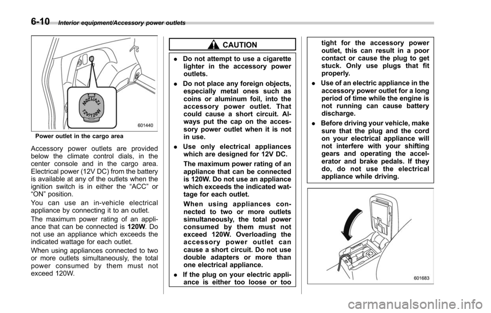
Power outlet in the cargo area
Accessory power outlets are provided
below the climate control dials, in the
center console and in the cargo area.
Electrical power (12V DC) from the battery
is available at any of the outlets when the
ignition switch is in either the“ACC ”or
“ON ”position.
Youcanuseanin-vehicleelectrical
appliance by connecting it to an outlet.
The maximum power rating of an appli-
ance that can be connected is 120W.Do
not use an appliance which exceeds the
indicated wattage for each outlet.
When using appliances connected to two
or more outlets simultaneously, the total
power consumed by them must not
exceed 120W.
CAUTION
. Do not attempt to use a cigarette
lighter in the accessory power
outlets.
. Do not place any foreign objects,
especially metal ones such as
coins or aluminum foil, into the
accessory power outlet. That
could cause a short circuit. Al-
ways put the cap on the acces-
sory power outlet when it is not
in use.
. Use only electrical appliances
which are designed for 12V DC.
The maximum power rating of an
appliance that can be connected
is 120W. Do not use an appliance
which exceeds the indicated wat-
tage for each outlet.
When using appliances con-
nected to two or more outlets
simultaneously, the total power
consumed by them must not
exceed 120W. Overloading the
accessory power outlet can
cause a short circuit. Do not use
double adapters or more than
one electrical appliance.
. If the plug on your electric appli-
ance is either too loose or too tight for the accessory power
outlet, this can result in a poor
contact or cause the plug to get
stuck. Only use plugs that fit
properly.
. Use of an electric appliance in the
accessory power outlet for a long
period of time while the engine is
not running can cause battery
discharge.
. Before driving your vehicle, make
sure that the plug and the cord
on your electrical appliance will
not interfere with your shifting
gears and operating the accel-
erator and brake pedals. If they
do, do not use the electrical
appliance while driving.
6-10
Page 409 of 634

Starting and operating/Fuel
left. Do not remove the cap
quickly. Fuel may be under pres-
sure and spray out of the fuel
filler neck, especially in hot
weather. If you hear a hissing
sound while you are removing
the cap, wait for the sound to
stop and then slowly open the
cap to prevent fuel from spraying
out and creating a fire hazard.
3. Set the fuel filler cap on the cap holder
inside the fuel filler lid.
WARNING
.When refueling, insert the fuel
nozzle securely into the fuel filler
pipe. If the nozzle is lifted or not
fully inserted, its automatic stop- ping mechanism may not func-
tion, causing fuel to overflow the
tank and creating a fire hazard.
. Stop refueling when the auto-
matic stop mechanism on the
fuel nozzle activates. If you con-
tinue to add fuel, temperature
changes or other conditions
may cause fuel to overflow from
the tank and create a fire hazard.
4. Stop filling the tank after the fuel filler
pump automatically stops. Do not add any
more fuel.
5. Put the cap back on, turn it clockwise
until you hear a clicking noise. Be certain
not to catch the tether under the cap while
tightening.
6. Close the fuel filler lid completely.
If you spill any fuel on the painted surface,
rinse it off immediately. Otherwise, the
painted surface could be damaged.
NOTE
. You will see the “”sign in the fuel
gauge. This indicates that the fuel filler
door (lid) is located on the right side of
the vehicle.
. If the fuel filler cap is not tightened
until it clicks or if the tether is caught
under the cap, the CHECK ENGINE warning light/malfunction indicator
light may illuminate. Refer to
“CHECK
ENGINE warning light/Malfunction in-
dicator light ”F 3-16.
CAUTION
. Never add any cleaning agents to
the fuel tank. The addition of a
cleaning agent may cause da-
mage to the fuel system.
. After refueling, turn the cap to the
right until it clicks to ensure that
it is fully tightened. If the cap is
not securely tightened, fuel may
leak out while the vehicle is being
driven or fuel spillage could
occur in the event of an accident,
creating a fire hazard.
. Do not let fuel spill on the exterior
surfaces of the vehicle. Because
fuel may damage the paint, be
sure to wipe off any spilled fuel
quickly. Paint damage caused by
spilled fuel is not covered under
the SUBARU Limited Warranty.
. Always use a genuine SUBARU
fuel filler cap. If you use the
wrong cap, it may not fit or have
proper venting and your fuel tank
and emission control system
may be damaged. It could also
7-6
Page 410 of 634

lead to fuel spillage and a fire.
. Immediately put fuel in the tank
whenever the low fuel warning
light illuminates. Engine misfires
as a result of an empty tank
could cause damage to the en-
gine. Continuing to operate your
vehicle at an extremely low fuel
level may result in a reduction of
engine performance.State emission testing (U.S.
only)
WARNING
Testing of an All-Wheel Drive model
must NEVER be performed on a
single two-wheel dynamometer. At-
tempting to do so will result in
uncontrolled vehicle movement and
may cause an accident or injuries to
persons nearby.
CAUTION
. At state inspection time, remem-
ber to tell your inspection or
service station in advance not to
place your SUBARU AWD vehicle
on a two-wheel dynamometer.
Otherwise, serious transmission
damage will result.
. Resultant vehicle damage due to
improper testing is not covered
under the SUBARU Limited War-
ranty and is the responsibility of
the state inspection program or
its contractors or licensees.
California and a number of federal states have Inspection/Maintenance programs to
inspect your vehicle
’s emission control
system. If your vehicle does not pass this
test, some states may deny renewal of
your vehicle’ s registration.
Your vehicle is equipped with a computer
that monitors the performance of the
engine’ s emission control system. Certi-
fied emission inspectors will inspect the
On-Board Diagnostic (OBDII) system as
part of the state emission inspection
process. The OBDII system is designed
to detect engine and transmission pro-
blems that might cause the vehicle emis-
sions to exceed allowable limits. OBDII
inspections apply to all 1996 model year
and newer passenger cars and trucks.
Over 30 states plus the District of Colum-
bia have implemented emission inspec-
tion of the OBDII system.
. The inspection of the OBDII system
consists of a visual operational check of
the “CHECK ENGINE ”warning light/mal-
function indicator light (MIL) and an
examination of the OBDII system with an
electronic scan tool.
. A vehicle
passes the OBDII system
inspection if proper operation of the
“ CHECK ENGINE ”warning light is ob-
served, there are no stored diagnostic
trouble codes, and the OBDII readiness
monitors are all complete.
Starting and operating/State emission testing (U.S. only)
–CONTINUED –7-7
Page 425 of 634

Starting and operating/Manual transmission
NOTE
.This device complies with Part 15 of
the FCC Rules and with RSS-210 of
Industry Canada. Operation is subject
to the following two conditions: (1) This
device may not cause harmful inter-
ference, and (2) this device must
accept any interference received, in-
cluding interference that may cause
undesired operation.
Changes or modifications not ex-
pressly approved by the party respon-
sible for compliance could void the
user ’s authority to operate the equip-
ment and void warranty.
. To comply with the FCC RF expo-
sure compliance requirements, no
change to the antenna or the device is
permitted. Any change to the antenna
or the device could result in the device
exceeding the RF exposure require-
ments and void user ’sauthorityto
operate the device.Manual transmission
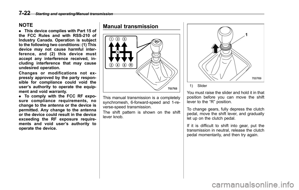
This manual transmission is a completely
synchromesh, 6-forward-speed and 1-re-
verse-speed transmission.
The shift pattern is shown on the shift
lever knob.
1) Slider
You must raise the slider and hold it in that
position before you can move the shift
lever to the “R”position.
To change gears, fully depress the clutch
pedal, move the shift lever, and gradually
let up on the clutch pedal.
If it is difficult to shift into gear, put the
transmission in neutral, release the clutch
pedal momentarily, and then try again.
7-22
Page 430 of 634

or foot brake is applied.
Avoid coasting with the transmission in
neutral. Engine braking has no effect in
this condition.
WARNING
Do not drive the vehicle with the
select lever in the“N ” (neutral)
position. Engine braking has no
effect in this condition and the risk
of an accident is consequently in-
creased.
NOTE
If the select lever is in the “N ” position
when you stop the engine for parking,
you may not subsequently be able to
move it to the “R ” and “P ” positions. If
this happens, turn the ignition switch to
the “ON ”position. You will then be able
to move the select lever to the “P ”
position.
! D (Drive)
This position is for normal driving. The
transmission shifts automatically and con-
tinuously into a suitable gear according to
the vehicle speed and the acceleration
you require. Also, while driving up and
down a hill, the transmission assists and controls the driving performance and
engine braking while corresponding to
the road grade.
When more acceleration is required in the
“
D ” position, depress the accelerator
pedal fully to the floor and hold that
position. The transmission will automati-
cally downshift. In this case, the transmis-
sion will operate lik e a conventional
automatic transmission. When you re-
lease the pedal, the transmission will
return to the original gear position.
For models with manual mode, if one of
the shift paddles behind the steering
wheel is operated while driving in the “D”
position, the transmission will temporarily
switch to the manual mode. In this mode,
you can shift into any gear position using
the shift paddles. For details about the
manual mode, refer to “Selection of
manual mode” F7-27. Once the vehicle
speed stabilizes, the transmission will
switch from the manual mode back to
the “D”position for normal driving.
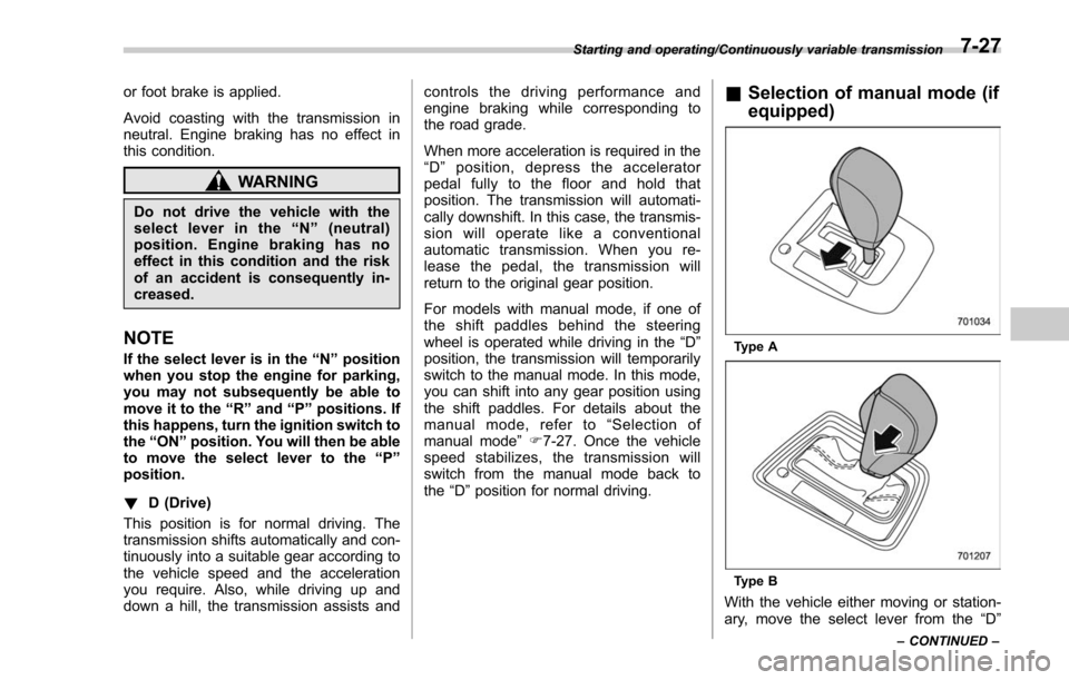
& Selection of manual mode (if
equipped)
Type A
Type B
With the vehicle either moving or station-
ary, move the select lever from the “D”
Starting and operating/Continuously variable transmission
–CONTINUED –7-27
Page 432 of 634

CAUTION
Do not place or hang anything on
the shift paddles. Doing so may
result in accidental gear shifting.
NOTE
Please read the following points care-
fully and bear them in mind when using
the manual mode.
.If you attempt to shift down when
the engine speed is too high, i.e., when
a downshift would push the tachometer
needle beyond the red zone, beeps will
be emitted to warn you that the down-
shift is not possible.
. If you attempt to shift up when the
vehicle speed is too low, the transmis-
sion will not respond.
. You can perform a skip-shift (for
example, from 4th to 2nd) by operating
the shift paddle twice in rapid succes-
sion.
. The transmission automatically se-
lects 1st gear when the vehicle stops
moving.
. If the temperature of the transmis-
sion fluid becomes too high, the “AT
OIL TEMP ”warning light on the combi-
nation meter will illuminate. Immedi-
ately stop the vehicle in a safe location and let the engine idle until the warning
light turns off.
.
For models with SI-DRIVE, by select-
ing Sport Sharp (S#) mode, upshifting
will not occur automatically. According
to the road conditions, shift change
manually so that the tachometer needle
does not enter the red zone. Also, if the
engine revolutions reach the specified
number, the fuel supply will be cut. In
this case, perform shift up operation.
& Selection of “L ” (if equipped)
Type A
Type B
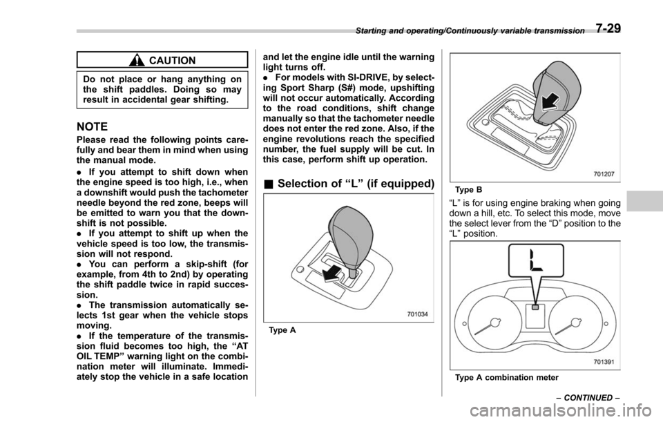
“L ” is for using engine braking when going
down a hill, etc. To select this mode, move
the select lever from the “D”position to the
“L ”position.
Type A combination meter
Starting and operating/Continuously variable transmission
–CONTINUED –
7-29
Page 435 of 634

Starting and operating/SI–DRIVE
SI-DRIVE (if equipped)
SI-DRIVE (SUBARU Intelligent Drive)
works to maximize engine performance,
control and efficiency.
This system consists of three modes:
Intelligent (I), Sport (S), and Sport Sharp
(S#). By operating the SI-DRIVE switches,
the character of the power unit changes.
&Intelligent (I) mode
! For smooth, efficient performance
driving
Type A combination meter
Type B combination meter
The linear acceleration characteristic of
the Intelligent (I) mode is ideal for normal
driving usage.
The Intelligent (I) mode provides well-
balanced performance with greater fuel
efficiency and smooth driveability without
stress. Power delivery is moderate during
acceleration for maximum fuel efficiency.
This is ideal for around-town driving and
situations that do not require full power
output. It provides better control in difficult
driving conditions, such as slippery roads
or loose surfaces, due to gentler throttle
response.
&Sport (S) mode
! For all-around performance driving
Type A combination meter
Type B combination meter
The Sport (S) mode provides the engine
7-32