2017 SUBARU FORESTER ESP
[x] Cancel search: ESPPage 176 of 634

!Vehicle Dynamics Control opera-
tion indicator light
The indicator light flashes during activa-
tion of the skid suppression function and
during activation of the traction control
function.
NOTE
. The light may remain illuminated for
a short period of time after the engine
has been started, especially in cold
weather. This does not indicate the
existence of a problem. The light
should turn off as soon as the engine
has warmed up.
. The indicator light illuminates when
the engine has developed a problem
and the CHECK ENGINE warning light/
malfunction indicator light is on.
The Vehicle Dynamics Control system is
probably malfunctioning under the follow-
ing condition. Have your vehicle checked
at a SUBARU dealer as soon as possible.
. The light does not turn off even after
the lapse of several minutes (the engine
has warmed up) after the engine has
started.
&Vehicle Dynamics
Control OFF indicator
light
The light illuminates when the Vehicle
Dynamics Control OFF switch is pressed
to deactivate the Vehicle Dynamics Con-
trol system.
The Vehicle Dynamics Control system is
probably malfunctioning under any of the
following conditions. Have your vehicle
checked at a SUBARU dealer immedi-
ately.
. The light does not illuminate when the
ignition switch is turned to the “ON ”
position.
. The light does not turn off even once
several seconds have elapsed after the
ignition switch has been turned to the
“ON ”position.
& Warning chimes and warning
light of the keyless access
with push-button start sys-
tem (if equipped)
Access key warning light (type A)
Access key warning light (type B)
Instruments and controls/Warning and indicator lights
–CONTINUED –
3-25
Page 184 of 634

&Steering Responsive
Headlight warning light/
Steering Responsive
Headlight OFF indicator
light (if equipped)
This light illuminates when the Steering
Responsive Headlight OFF switch is
pressed to deactivate the Steering Re-
sponsive Headlight. Also, the light flashes
when a malfunction occurs in the Steering
Responsive Headlight. Refer to“Steering
Responsive Headlight (SRH) ”F 3-99.
&Front fog light indicator
light (if equipped)
This indicator light illuminates while the
front fog lights are illuminated.
&Headlight indicator
light (if equipped)
This indicator light illuminates under the
following conditions.
. when the light switch is turned to the
“
” or “”position
. when the light control switch is in the
“AUTO ”position and the headlights illumi-
nate automatically
&X-mode indicator light
(if equipped)
This light illuminates while the X-mode is
activated. It will turn off when the X-mode
is deactivated. Refer to “To activate/
deactivate the X-mode ”F 7-43.
&Hill descent control
indicator light (if
equipped)
This indicator illuminates while the hill
descent control function is in standby. It
will flash while the hill descent control
function is operating. It will turn off when
the hill descent control function is not
available. Refer to “Hill descent control
function ”F 7-44.
&Steering responsive
fog lights warning indi-
cator/Steering respon-
sive fog lights OFF in-
dicator (if equipped)
NOTE
For details about the steering respon-
sive fog lights system, refer to “Steer-
ing responsive fog lights system ”F 3-
103. !
Steering responsive fog lights
warning indicator
This indicator starts blinking when the
steering responsive fog lights system
malfunctions. When this indicator is blink-
ing while the system is activated, contact
your SUBARU dealer for an inspection.
! Steering responsive fog lights OFF
indicator
This indicator appears when the steering
responsive fog lights system is deacti-
vated. This indicator disappears when the
system is activated.
&BSD/RCTA warning in-
dicator (if equipped)
This warning indicator appears when the
BSD/RCTA is malfunctioning.
For models with type A combination
meter, the BSD/RCTA warning indicator
will be shown on the combination meter.
For models with type B combination
meter, the BSD/RCTA warning indicator
will be shown on the multi information
display of the combination meter.
When this indicator appears, have your
vehicle inspected by your SUBARU dealer
as soon as possible.
Instruments and controls/Warning and indicator lights
–CONTINUED –3-33
Page 187 of 634

Instruments and controls/Information display (Mexico–spec. models)
the average rate of fuel consumption.
When the low fuel warning light illumi-
nates, the driving range display flashes for
5 seconds. (The display first switches to
the driving range value if a different value
was previously displayed.)
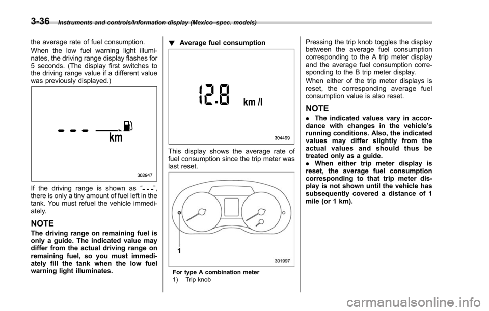
If the driving range is shown as “”,
there is only a tiny amount of fuel left in the
tank. You must refuel the vehicle immedi-
ately.
NOTE
The driving range on remaining fuel is
only a guide. The indicated value may
differ from the actual driving range on
remaining fuel, so you must immedi-
ately fill the tank when the low fuel
warning light illuminates. !
Average fuel consumption
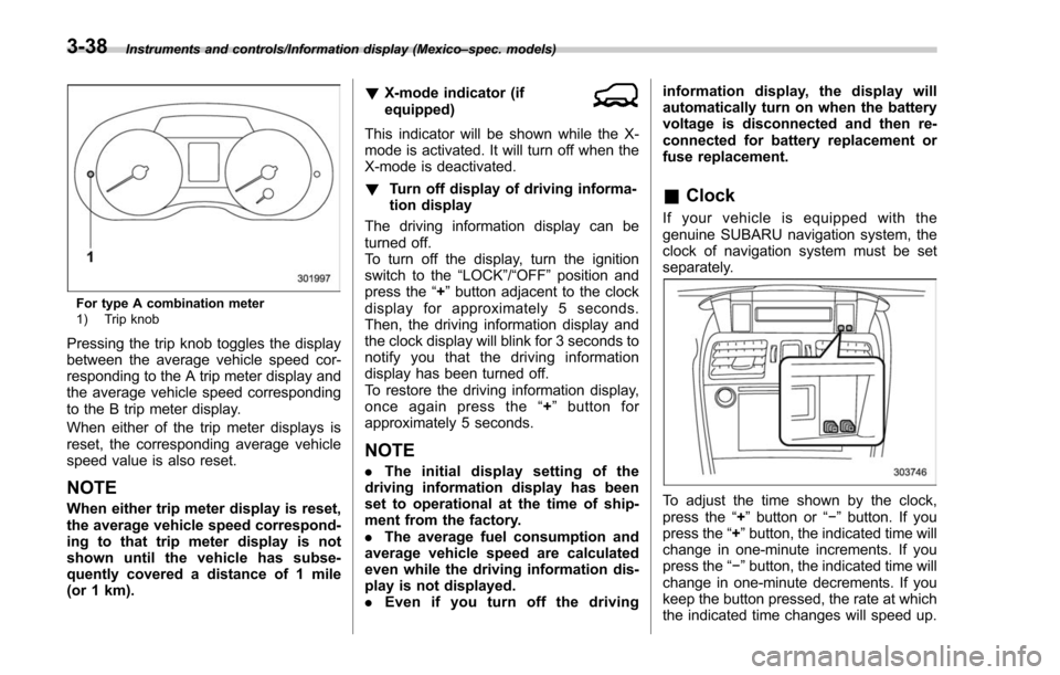
This display shows the average rate of
fuel consumption since the trip meter was
last reset.
For type A combination meter
1) Trip knob
Pressing the trip knob toggles the display
between the average fuel consumption
corresponding to the A trip meter display
and the average fuel consumption corre-
sponding to the B trip meter display.
When either of the trip meter displays is
reset, the corresponding average fuel
consumption value is also reset.
NOTE
.The indicated values vary in accor-
dance with changes in the vehicle ’s
running conditions. Also, the indicated
values may differ slightly from the
actual values and should thus be
treated only as a guide.
. When either trip meter display is
reset, the average fuel consumption
corresponding to that trip meter dis-
play is not shown until the vehicle has
subsequently covered a distance of 1
mile (or 1 km).
3-36
Page 189 of 634

Instruments and controls/Information display (Mexico–spec. models)
For type A combination meter
1) Trip knob
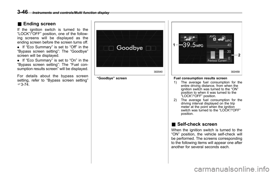
Pressing the trip knob toggles the display
between the average vehicle speed cor-
responding to the A trip meter display and
the average vehicle speed corresponding
to the B trip meter display.
When either of the trip meter displays is
reset, the corresponding average vehicle
speed value is also reset.
NOTE
When either trip meter display is reset,
the average vehicle speed correspond-
ing to that trip meter display is not
shown until the vehicle has subse-
quently covered a distance of 1 mile
(or 1 km). !
X-mode indicator (if
equipped)
This indicator will be shown while the X-
mode is activated. It will turn off when the
X-mode is deactivated.
! Turn off display of driving informa-
tion display
The driving information display can be
turned off.
To turn off the display, turn the ignition
switch to the “LOCK”/“OFF”position and
press the “+”button adjacent to the clock
display for approximately 5 seconds.
Then, the driving information display and
the clock display will blink for 3 seconds to
notify you that the driving information
display has been turned off.
To restore the driving information display,
once again press the “+ ” button for
approximately 5 seconds.
NOTE
. The initial display setting of the
driving information display has been
set to operational at the time of ship-
ment from the factory.
. The average fuel consumption and
average vehicle speed are calculated
even while the driving information dis-
play is not displayed.
. Even if you turn off the driving information display, the display will
automatically turn on when the battery
voltage is disconnected and then re-
connected for battery replacement or
fuse replacement.
&
Clock
If your vehicle is equipped with the
genuine SUBARU navigation system, the
clock of navigation system must be set
separately.
To adjust the time shown by the clock,
press the “+”button or “− ” button. If you
press the “+ ”button, the indicated time will
change in one-minute increments. If you
press the “− ”button, the indicated time will
change in one-minute decrements. If you
keep the button pressed, the rate at which
the indicated time changes will speed up.
3-38
Page 197 of 634

Instruments and controls/Multi function display
&Ending screen
If the ignition switch is turned to the
“LOCK”/ “OFF ”position, one of the follow-
ing screens will be displayed as the
ending screen before the screen turns off.
. If“Eco Summary ”is set to “Off ”in the
“Bypass screen setting ”: The“Goodbye ”
screen will be displayed.
. If“Eco Summary ”is set to “On”in the
“ Bypass screen setting ”: The “Fuel con-
sumption results screen” will be displayed.
For details about the bypass screen
setting, refer to “Bypass screen setting ”
F 3-74.
“Goodbye ”screenFuel consumption results screen
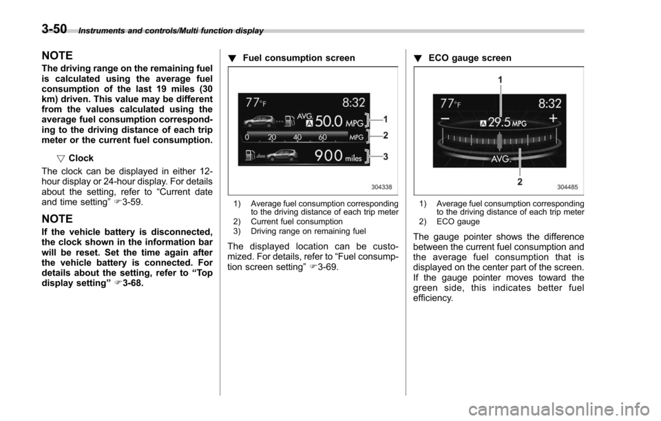
1) The average fuel consumption for the
entire driving distance, from when the
ignition switch was turned to the “ON ”
position to when it was turned to the
“ LOCK ”/“ OFF ”position.
2) The average fuel consumption for the driving interval displayed on the trip
meter at the point when the ignition
switch was turned to the “LOCK ”/“ OFF ”
position.
& Self-check screen
When the ignition switch is turned to the
“ON ”position, the vehicle self-check will
be performed. The screens corresponding
to the following items will appear one after
another for several seconds each.
3-46
Page 198 of 634

Type A combination meter
1) Engine oil: Checks the interval of engineoil replacement.
2) Oil filter: Checks the interval of oil filter replacement.
3) Tires: Checks the interval of tire rotation.
4) Inspection and maintenance: Checks the interval of inspection and maintenance.Type B combination meter
1) Windshield washer fluid: Checks thelevel of windshield washer fluid.
2) Brake fluid: Checks the level of brake fluid.
3) Engine oil: Checks the interval of engine oil replacement.
4) Oil filter: Checks the interval of oil filter replacement.
5) Tires: Checks the interval of tire rotation.
6) Inspection and maintenance: Checks the interval of inspection and maintenance.
When the checks are performed, the color
of the icon corresponding to the checked
item will turn green.
If there is no warning message, the self-
check will complete without notification.
Example of notification
If there is a warning message or a
maintenance notification, the color of the
icon corresponding to the item will turn
yellow and the warning message or the
maintenance notification will be displayed.
Take the appropriate actions based on the
messages indicated.
NOTE
.The self-check screen can be set to
on or off. For details, refer to “On/Off
setting ”F 3-77.
. After performing the maintenance,
change the setting of the correspond-
ing maintenance item. For details, refer
to “Maintenance settings ”F 3-76.
. The maintenance notification screen
will be displayed under either of the
Instruments and controls/Multi function display
–CONTINUED –3-47
Page 200 of 634

!Information bar
1) Information bar
2) Outside temperature indicator
3) Information reminder (models with type A
combination meter)
4) Top display
5) Clock
While the ignition switch is in the “ACC ”or
“ON ”position, the outside temperature
indicator, clock, etc. will be shown on the
information bar.
!Outside temperature indicator
This displays the outside temperature
between −408 F( −408 C) and 122 8F
(50 8C).
Icy road surface warning screen
When the outside temperature becomes
37 8F(3 8C) or less, the icy road surface
warning screen interrupts to inform the
driver that the road surface may be frozen.
NOTE
. The outside temperature indicator
shows the temperature around the
sensor. Therefore, the temperature in-
dication may differ from the actual
outside air temperature.
. The icy road surface warning screen
should be treated only as a guide. Be
sure to check the condition of the road
surface before driving.
. Once the icy road surface warning
screen is displayed, it will not be
displayed again unless the ignition switch is turned to the
“ACC ”or “ON ”
position after it has been turned to
“ LOCK ”/“ OFF ”position.
! Information reminder
The screen returns to the original screen
several seconds after the interruption
screen has been displayed. If the inter-
ruption screen can be displayed once
more even after the original screen has
appeared, an information reminder should
be displayed. For details about the inter-
ruption screen, refer to “Interruption
screen” F3-48.
! Top display
One of the following items can be dis-
played on the top display.
. Average fuel consumption correspond-
ing to the driving distance of each trip
meter
. Current fuel consumption (This may
not be displayed when driving at a low
speed.)
. Driving range on remaining fuel
For details about the setting of the top
display, refer to “Top display setting ”F 3-
68.
Instruments and controls/Multi function display
–CONTINUED –3-49
Page 201 of 634

Instruments and controls/Multi function display
NOTE
The driving range on the remaining fuel
is calculated using the average fuel
consumption of the last 19 miles (30
km) driven. This value may be different
from the values calculated using the
average fuel consumption correspond-
ing to the driving distance of each trip
meter or the current fuel consumption.!Clock
The clock can be displayed in either 12-
hour display or 24-hour display. For details
about the setting, refer to “Current date
and time setting ”F 3-59.
NOTE
If the vehicle battery is disconnected,
the clock shown in the information bar
will be reset. Set the time again after
the vehicle battery is connected. For
details about the setting, refer to “To p
display setting ”F 3-68. !
Fuel consumption screen
1) Average fuel consumption corresponding
to the driving distance of each trip meter
2) Current fuel consumption
3) Driving range on remaining fuel
The displayed location can be custo-
mized. For details, refer to “Fuel consump-
tion screen setting ”F 3-69. !
ECO gauge screen
1) Average fuel consumption corresponding
to the driving distance of each trip meter
2) ECO gauge
The gauge pointer shows the difference
between the current fuel consumption and
the average fuel consumption that is
displayed on the center part of the screen.
If the gauge pointer moves toward the
green side, this indicates better fuel
efficiency.
3-50