2017 RENAULT ALASKAN lights
[x] Cancel search: lightsPage 9 of 340

1.
Bonnet (P. 3-17)
2. Windscreen wipers and washers
—S
witch operation (P. 2-34)
—W iper blade replacement (P. 8-16)
—W indow washer fluid (P. 8-11)
3. Sunroof*1 (P. 2-42)
4. Windows (P. 2-36) 5.
Roof rail*1 (P. 2-41)
6. Child safety rear door locks*1 (P. 3-5)
7. Doors
—K
eys (P. 3-2)
—D oor locks (P. 3-4)
—R emote keyless entry system*1 (P. 3-6)
—R emote Control Key system*1 (P. 3-7)
—S ecurity system*1 (P. 3-15) 8.
Outside rearview mirrors (P. 3-25)
9. Side turn signal lights
—B
ulb replacement (P. 8-23)
10. Tyres
—T
yres and wheels (P. 8-26)
—F lat tyre (P. 6-2)
—S pecifications (P. 9-4)
—F our-Wheel Drive (4WD)*1 (P. 5-32)
11. Headlights and turn signal lights
—S
witch operation (P. 2-31)
—B ulb replacement (P. 8-21)
12. Headlight cleaner*1
—O
peration (P. 2-35)
13. Front fog lights*1 or Daytime running lights*1
—S
witch operation (P. 2-33, P. 2-31)
—B ulb replacement (P. 8-23)
14. Towing eye*2 (P. 6-13)
*1: where fitted
*2: The layout illustrated is for the Right-Hand
Drive (RHD) model. On the Left-Hand Drive
(LHD) model, the towing eye is located on the
opposite side. NIC3080
EXTERIOR FRONT
Illustrated table of contents0-3
Page 10 of 340

1.
Rear window defogger* (P. 2-34)
2. High-mounted stop light* (P. 5-49)
3. Antenna* (P. 4-35)
4. AdBlue filler lid (P. 3-19)
5. Rear view camera*
—R
eversing camera* (P. 4-7) 6.
Cargo bed* (P. 3-20)
7. Rear combination lights (bulb replacement)
(P. 8-23)
8. Number plate lights (bulb replacement)
(P. 8-23)
9. Parking sensor (sonar)* (P. 5-46)
*: where fitted NIC3081
EXTERIOR REAR
0-4 Illustrated table of contents
Page 11 of 340

1.
Inside rearview mirror (P. 3-23)
2. Sunglasses holder* (P. 2-40)
3. Microphone*
—B
luetooth® Hands-Free Phone System*
(P. 4-59, P. 4-65)
4. Sunroof switch* (P. 2-42)
5. Map lights (P. 2-43) 6.
Sun visors (P. 2-41)
7. Room light* (P. 2-44)
8. Rear personal light* (P. 2-45)
9. Console box* (P. 2-40)
—P
ower outlet (P. 2-38)
10. Cup holders* (P. 2-40) 11.
Door armrest
—P
ower window controls* (P. 2-36)
—P ower door lock switch (driver’s door)*
(P. 3-4)
—O utside rearview mirror remote control
switch (driver’s door)* (P. 3-25)
*: where fitted NIC2792
PASSENGER COMPARTMENT
Illustrated table of contents0-5
Page 16 of 340

1.
Tachometer (P. 2-3)
2. Warning and indicator lights (P. 2-3)
3. Vehicle information display (P. 2-14)
—F
our-Wheel Drive (4WD) mode indicator*
(P. 5-30)
—O il control system* (P. 2-29)
—O dometer/twin trip odometer (P. 2-3)
—T rip computer (P. 2-21) —I
nstrument brightness control (P. 2-4)
—A utomatic Transmission (AT) position
indicator (AT model) (P. 2-28, P. 5-19)
4. Speedometer (P. 2-2)
5. Fuel gauge (P. 2-2)
6. Engine coolant temperature gauge (P. 2-3)
*: where fitted NIC2681
METERS AND GAUGES
0-10 Illustrated table of contents
Page 48 of 340

Supplemental side-impact air bag
system (where fitted)
This system can help cushion the impact force to
the chest and pelvis area of the driver and front pas-
senger in certain side-impact collisions. The supple-
mental side-impact air bag is designed to inflate on
the side where the vehicle is impacted.
Supplemental curtain side-impact air
bag system (where fitted)
This system can help cushion the impact force to
the head of the driver and passengers in front seat-
ing positions and rear outboard seating positions
(where fitted) in certain side-impact collisions. The
supplemental curtain side-impact air bag is designed
to inflate on the side where the vehicle is impacted.
The SRS is designed to supplementthe accident
protection provided by the driver’s and passenger’s
seat belts and is notdesigned to substitutefor
them. The SRS can help save lives and reduce seri-
ous injuries. However, inflating air bags may cause
abrasions or other injuries. Air bags do not provide
protection to the lower body. Seat belts should al-
ways be correctly worn and the occupants should
always be seated asuitable distance away from the
steering wheel, instrument panel and door finishers.
(See “Seat belts” earlier in this section.) The air
bags inflate quickly in order to help protect the oc-
cupants. The force of the air bags inflating can in-
crease the risk of injury if the occupants are too
close to, or are against, the air bag modules during
inflation. The air bags will deflate quickly after de-
ployment. The SRS operates only when the ignition switch
is in the ON position.
When the ignition switch is in the ON position,
the SRS air bag warning light illuminates for
about
7seconds and then turns off. This indi-
cates that the SRS is operational. (See “Warning
lights, indicator lights and audible reminders” in
the “2. Instruments and controls” section.)
1-30 Safety —seats, seat belts and supplemental restraint system
Page 56 of 340

•
Do not fit
arearward facing child seat on the
front passenger seat if the air bag activation/
deactivation system (where fitted) is malfunc-
tioning. Your vehicle must immediately be
taken to an approved dealer or qualified work-
shop in such asituation.
The front passenger air bag status lights and
are located on the instrument panel between
the centre vents.
When the ignition switch is placed in the ON posi-
tion, the front passenger air bag status ON and
OFF lights illuminate and then turn off or remain on
depending on the front passenger air bag status.
• When the ignition switch is placed in the ON
position and the front passenger air bag is ac-
tive, both the front passenger air bag status OFF
light ,a
nd the Supplemental Restraint Sys-
tem (SRS) air bag warning light in the com-
bination meter ➀will turn off after about
7sec-
onds.
The front passenger air bag status ON light will illuminate and then turn off after
aperiod of
time when the front passenger air bag switch is
in the ON position.
• When the ignition switch is placed in the ON
position and the front passenger air bag is inac-
tive, both the front passenger air bag status ON
light ,a
nd the Supplemental Restraint Sys-
tem (SRS) air bag warning light in the com-
bination meter ➀will turn off after about
7sec-
onds. The front passenger air bag status OFF light will illuminate and remain on as long as the
front passenger air bag switch is in the OFF
position.
If the front passenger air bag status light operates in
aw ay other than described above, the front passen-
ger air bag may not function properly. Have the sys-
tem checked, and if necessary repaired, by an ap-
proved dealer or qualified workshop promptly.
Front passenger air bag switch (where fitted):
The front passenger air bag can be turned off with
the front passenger air bag switch j
Al ocated in-
side the glove box.
j A Air bag switch (where fitted)
j B Left Hand Drive models
j C Right Hand Drive models
To turn off the front passenger air bag:
1. Place the ignition switch in the OFFposition. 2. Open the glove box and insert the key into the
front passenger air bag switch. For Remote Con-
trol Key equipped models, see “Keys” in the
“3. Pre-driving checks and adjustments” section
for mechanical key usage.
3. Push and turn the key to the
4. Place the ignition switch in the ONposition. The
front passenger air bag status OFF light will illuminate and remain on.
To turn on the front passenger air bag:
1. Place the ignition switch in the OFFposition.
2. Open the glove box and insert the key into the front passenger air bag switch.
3. Push and turn the key to the
4. Place the ignition switch in the ONposition. The
front passenger air bag status ON light will
illuminate, and after
aperiod of time, will then
turn off.
Supplemental driver’s knee air bag
system (where fitted)
The supplemental driver’s knee air bag is located
under the steering column.
The supplemental driver’s knee air bag system is
designed to inflate in higher severity frontal colli-
sions, although it may inflate if the forces in another
type of collision are similar to those of ahigher se-
verity impact. It may not inflate in certain collisions. NP A1296
1-38 Safety —seats, seat belts and supplemental restraint system
Page 59 of 340

2
Instruments and controls
Instruments and controls
Meters and gauges .................................................. 2-2 Speedometer and Fuel gauge ............................. 2-2
Tachometer and Engine coolant temperature
gauge ................................................................. 2-3
Instrument brightness control .............................. 2-4
Warning lights, indicator lights and audible
reminders ................................................................ 2-5 Checking lights................................................... 2-6
Warning lights .................................................... 2-6
Indicator lights .................................................... 2-12
Audible reminders............................................... 2-14
Vehicle information display ....................................... 2-14
How to use the Vehicle Information Display ......... 2-15
Settings .............................................................. 2-15
Trip computer ..................................................... 2-21
Indicators for operation ....................................... 2-25
Oil control system (where fitted for diesel
engine model) ..................................................... 2-29
Clock and outside air temperature (where
fitted).................................................................. 2-30
Headlight and turn signal switch............................... 2-31 Headlight switch ................................................. 2-31
Headlight aiming control (where fitted) ................ 2-32
Battery saver system (where fitted) ..................... 2-32
Turn signal switch ............................................... 2-32
Fog light switch (where fitted) .................................. 2-33
Front fog lights (where fitted) .............................. 2-33
Rear fog light (where fitted)................................. 2-33
Wiper and washer switch ........................................ 2-34 Windscreen wiper and washer switch ................. 2-34
Defogger switch (where fitted) ................................. 2-34
Headlight cleaner (where fitted) ............................... 2-35 Headlight cleaner switch (where fitted) ............... 2-35
Horn ........................................................................V
2-36
Windows ................................................................. 2-36 Manual windows (where fitted) ........................... 2-36
Power windows (where fitted)............................. 2-36
Power outlets .......................................................... 2-38
Storage ................................................................... 2-39 Glove box ........................................................... 2-39
Console box ....................................................... 2-40
Sunglasses holder .............................................. 2-40
Console side pockets ......................................... 2-40
Cup holders (where fitted) .................................. 2-40
Roof rail (where fitted) ........................................ 2-41
Card holder (where fitted)................................... 2-41
Sun visors ............................................................... 2-41
Sunroof (where fitted) .............................................. 2-42 Automatic sunroof............................................... 2-42
Interior lights ............................................................ 2-43 Interior light switch (where fitted) ........................ 2-43
Console light (where fitted) ................................. 2-43
Map lights........................................................... 2-43
Map light control switch (where fitted)................. 2-44
Room light (where fitted)..................................... 2-44
Rear personal light (where fitted) ........................ 2-45
Vanity mirror lights (where fitted) ......................... 2-45
Battery saver system........................................... 2-45
Page 62 of 340

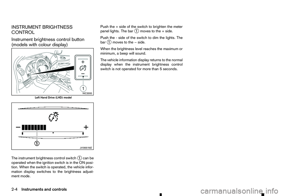
INSTRUMENT BRIGHTNESS
CONTROL
Instrument brightness control button
(models with colour display)
The instrument brightness control switch ➀can be
operated when the ignition switch is in the ON posi-
tion. When the switch is operated, the vehicle infor-
mation display switches to the brightness adjust-
ment mode. Push the
+side of the switch to brighten the meter
panel lights. The bar ➀moves to the
+side.
Push the -side of the switch to dim the lights. The
bar ➀moves to the
−side.
When the brightness level reaches the maximum or
minimum, abeep will sound.
The vehicle information display returns to the normal
display when the instrument brightness control
switch is not operated for more than 5seconds. NIC3095
Left Hand Drive (LHD) model
JVI0661MZ
2-4 Instruments and controls