2017 PEUGEOT 5008 tow
[x] Cancel search: towPage 251 of 404
249
Trailers with LED lamps are not
compatible with the wiring harness of this
device.
To know the technical features, and in
particular the towable weights for your
vehicle, refer to the corresponding section.
For advice on driving safely when To w i n g
a trailer , refer to the corresponding
section.
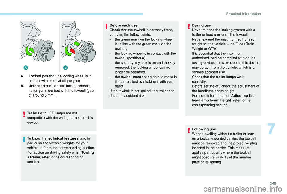
A.
Locked position; the locking wheel is in
contact with the towball (no gap).
B. Unlocked position; the locking wheel is
no longer in contact with the towball (gap
of around 5 mm). Before each use
Check that the towball is correctly fitted,
verifying the follow points:
-
t
he green mark on the locking wheel
is in line with the green mark on the
towball,
-
t
he locking wheel is in contact with the
towball (position A ),
-
t
he security key lock is on and the key
removed; the locking wheel can no
longer be operated,
-
t
he towball must not be able to move in
its carrier; test by shaking it with your
hand.
If the towball is not locked, the trailer can
detach – accident risk! During use
Never release the locking system with a
trailer or load carrier on the towball.
Never exceed the maximum authorised
weight for the vehicle – the Gross Train
Weight or GTW.
It is essential that the maximum
authorised load be complied with on the
towing device: if it is exceeded, this device
may detach from the vehicle, which is a
serious accident risk.
Check that the trailer lamps work
c o r r e c t l y.
Before setting off, check the adjustment of
the headlamp beam height.
For more information on Adjusting the
headlamp beam height
, refer to the
corresponding section.
Following use
When travelling without a trailer or load
on a towbar-mounted carrier, the towball
must be removed and the protective plug
inserted in the carrier. This measure
applies particularly where the towball
might obscure visibility of the number
plate or its lighting.
7
Practical information
Page 252 of 404
250
Fitting the towball
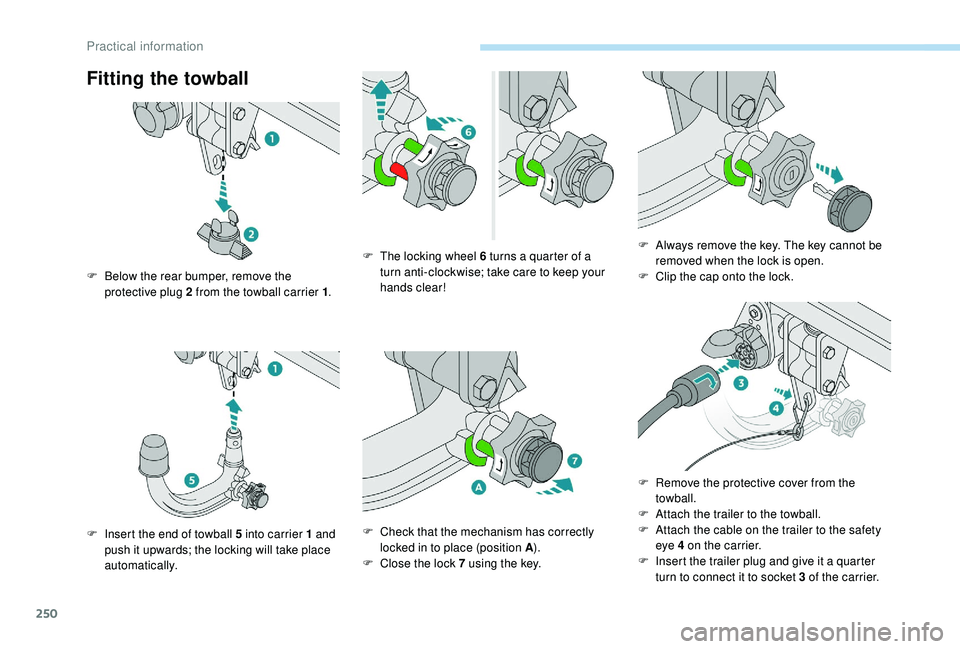
F Below the rear bumper, remove the protective plug 2 from the towball carrier 1 .
F
I
nsert the end of towball 5 into carrier 1 and
push it upwards; the locking will take place
automatically. F
T
he locking wheel 6 turns a quarter of a
turn anti-clockwise; take care to keep your
hands clear!
F
C
heck that the mechanism has correctly
locked in to place (position A ).
F
C
lose the lock 7 using the key.F
A
lways remove the key. The key cannot be
removed when the lock is open.
F C lip the cap onto the lock.
F
R
emove the protective cover from the
towball.
F
A
ttach the trailer to the towball.
F
A
ttach the cable on the trailer to the safety
eye 4
on the carrier.
F
I
nsert the trailer plug and give it a quarter
turn to connect it to socket 3
of the carrier.
Practical information
Page 253 of 404
251
Removing the towball
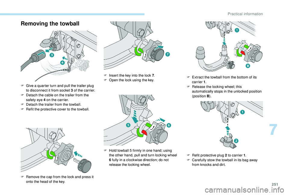
F Give a quarter turn and pull the trailer plug to disconnect it from socket 3 of the carrier.
F
D
etach the cable on the trailer from the
safety eye 4
on the carrier.
F
D
etach the trailer from the towball.
F
R
efit the protective cover to the towball.
F
R
emove the cap from the lock and press it
onto the head of the key. F
I
nsert the key into the lock 7
.
F
O
pen the lock using the key.
F
H
old towball 5 firmly in one hand; using
the other hand, pull and turn locking wheel
6
fully in a clockwise direction; do not
release the locking wheel. F
E
xtract the towball from the bottom of its
carrier 1 .
F R elease the locking wheel; this
automatically stops in the unlocked position
(position B ).
F
R
efit protective plug 2 to carrier 1.
F
C
arefully stow the towball in its bag away
from knocks and dirt.
7
Practical information
Page 254 of 404
252
Apply the label provided to a clearly visible
area, close to the carrier or in the boot.
Go to a PEUGEOT dealer or a qualified
workshop for any work on the towbar
system.
Load reduction mode
System which manages the use of certain
functions according to the level of charge
remaining in the battery.
When the vehicle is being driven, the load
reduction function temporarily deactivates
certain functions, such as air conditioning,
heated rear screen, etc.
The deactivated functions are reactivated
automatically as soon as conditions permit.
Maintenance
Correct operation is only possible if the towball
and its carrier are kept clean.
Before cleaning the vehicle with a high-
pressure jet wash, the towball must be removed
and the protective plug fitted to the carrier.
Energy economy mode
System which manages the duration of use of
certain functions to conser ve a sufficient level
of charge in the battery.
After the engine has stopped, you can still use
functions such as the audio and telematics
system, windscreen wipers, dipped beam
headlamps, courtesy lamps, etc. for a
maximum combined duration of about forty
minutes.
Switching to this mode
A message appears in the instrument panel
screen indicating that the vehicle has switched
to economy mode and the active functions are
put on standby.If a telephone call is being made at this
time, it will be maintained for around
10
minutes with the Bluetooth hands-free
system of your audio system.
Exiting the mode
These functions will be automatically restored
the next time the vehicle is used.
In order to restore the use of these functions
immediately, start the engine and let it run:
-
f
or less than ten minutes, to use the
equipment for approximately five minutes,
-
f
or more than ten minutes, to use the
equipment for up to approximately thirty
minutes.
Let the engine run for the duration specified to
ensure that the battery charge is sufficient.
Do not repeatedly and continuously restart the
engine in order to charge the battery.
A flat battery prevents the engine from
starting.
For more information on the 12
V batter y,
refer to the corresponding section.
Practical information
Page 255 of 404
253
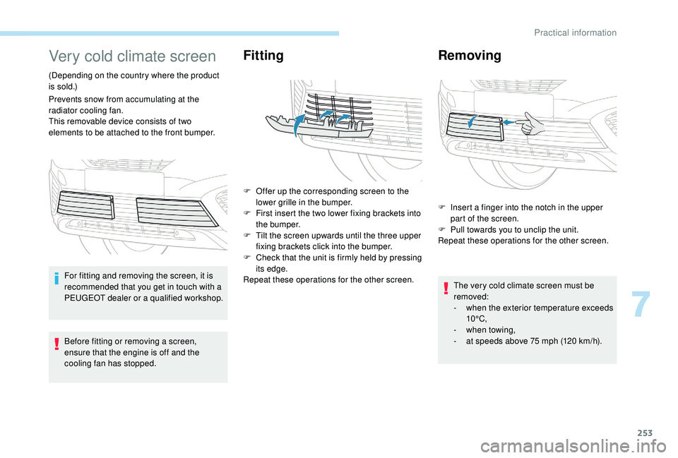
Very cold climate screen
(Depending on the country where the product
is sold.)
Prevents snow from accumulating at the
radiator cooling fan.
This removable device consists of two
elements to be attached to the front bumper.For fitting and removing the screen, it is
recommended that you get in touch with a
PEUGEOT dealer or a qualified workshop.
Before fitting or removing a screen,
ensure that the engine is off and the
cooling fan has stopped.
Fitting
F Offer up the corresponding screen to the lower grille in the bumper.
F
F
irst insert the two lower fixing brackets into
the bumper.
F
T
ilt the screen upwards until the three upper
fixing brackets click into the bumper.
F
C
heck that the unit is firmly held by pressing
its edge.
Repeat these operations for the other screen.
Removing
F Insert a finger into the notch in the upper part of the screen.
F
P
ull towards you to unclip the unit.
Repeat these operations for the other screen.
The very cold climate screen must be
removed:
-
w
hen the exterior temperature exceeds
10°C,
-
w
hen towing,
-
a
t speeds above 75 mph (120 km/h).
7
Practical information
Page 258 of 404
256
Bonnet
Before doing anything under the bonnet,
deactivate the Stop & Start system to
avoid any risk of injury resulting from an
automatic change to START mode.
The location of the interior bonnet release
lever prevents opening of the bonnet when
the left-hand front door is shut.
When the engine is hot, handle the
exterior safety catch and the stay with
care (risk of burns), using the protected
area.
When the bonnet is open, take care not to
damage the safety catch.
Do not open the bonnet under very windy
conditions.
The cooling fan may star t after
switching off the engine: take care
with articles and clothing that might be
caught by the fan blades.
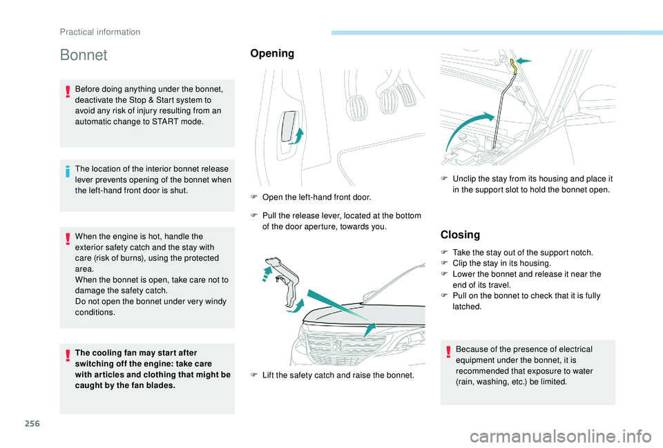
Opening
F Open the left-hand front door.
F
P
ull the release lever, located at the bottom
of the door aperture, towards you.
F
L
ift the safety catch and raise the bonnet. F
U
nclip the stay from its housing and place it
in the support slot to hold the bonnet open.
Closing
F Take the stay out of the support notch.
F C lip the stay in its housing.
F
L
ower the bonnet and release it near the
end of its travel.
F
P
ull on the bonnet to check that it is fully
latched.
Because of the presence of electrical
equipment under the bonnet, it is
recommended that exposure to water
(rain, washing, etc.) be limited.
Practical information
Page 263 of 404
261
Air filter and passenger compartment filter
Refer to the manufacturer's
ser vice schedule for details of the
replacement intervals for these
components.
Depending on the environment (e.g. dusty
atmosphere) and the use of the vehicle (e.g.
city driving), replace them twice as often if
necessary .
A clogged passenger compartment filter may
have an adverse effect on the per formance
of the air conditioning system and generate
undesirable odours.
Oil filter
Change the oil filter each time the
engine oil is changed.
Refer to the manufacturer's
ser vice schedule for details of
the replacement inter val for this
component.
Particle filter (Diesel)
The start of saturation of the particle
filter is indicated by the temporary
illumination of this warning lamp
accompanied by a message about
the risk of the filter clogging up. As soon as the traffic conditions permit,
regenerate the filter by driving at a speed
of at least 40
mph (60 km/h) until the
warning lamp goes off.
If the warning lamp stays on, this indicates
a low Diesel additive level.
For more information on Checking levels ,
refer to the corresponding section.
On a new vehicle, the first particle
filter regeneration operations may be
accompanied by a "burning" smell, which
is per fectly normal.
Following prolonged operation of the
vehicle at very low speed or at idle,
you may, in exceptional circumstances,
notice the emission of water vapour at the
exhaust on acceleration. This does not
affect the behaviour of the vehicle or the
environment.
Manual gearbox
The gearbox does not require any
maintenance (no oil change).
Refer to the manufacturer's service
schedule for the checking inter val
for this component.
Automatic gearbox
The gearbox does not require any
maintenance (no oil change).
Refer to the manufacturer’s service
schedule for the checking inter val
for this component.
Brake pads
Brake wear depends on the style
of driving, particularly in the case
of vehicles used in town, over short
distances. It may be necessary to
have the condition of the brakes
checked, even between vehicle
services.
Unless there is a leak in the circuit, a drop in
the brake fluid level indicates that the brake
pads are worn.
7
Practical information
Page 269 of 404
267
Engine 2.0 HDi
F Fill the fuel tank with at least five litres of Diesel.
F
O
pen the bonnet.
F
I
f necessary, unclip the cover to access the
priming pump.
F
L
oosen the degassing bolt.
F
U
se the priming pump until fuel appears in
the transparent tube.
F
R
etighten the degassing bolt.
F
O
perate the starter until the engine starts (if
the engine does not start at the first attempt,
wait around 15
seconds before trying
again).
F
I
f the engine does not start after a few
attempts, operate the priming pump again
then start the engine.
F
P
ut it back in place, clip in the cover and
ensure it is clipped in.
F
C
lose the boot again.
Tool kit
This is a set of tools provided with the vehicle.
Its content depends on your vehicle's
equipment:
-
t
emporary puncture repair kit,
-
spar
e wheel.
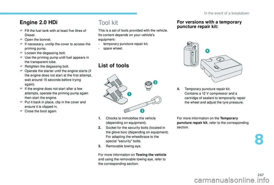
List of tools
1.Chocks to immobilise the vehicle
(depending on equipment).
2. Socket for the security bolts (located in
the glove box) (depending on equipment).
For adapting the wheelbrace to the
special "security" bolts.
3. Removable towing eye.
For more information on Towing the vehicle
and using the removable towing eye, refer to
the corresponding section.
For versions with a temporary
puncture repair kit:
For more information on the Temporary
puncture repair kit , refer to the corresponding
section. 4. Temporary puncture repair kit.
Contains a 12 V compressor and a
cartridge of sealant to temporarily repair
the wheel and adjust the tyre pressure.
8
In the event of a breakdown