Page 17 of 53

3. Preparation for Dismantling
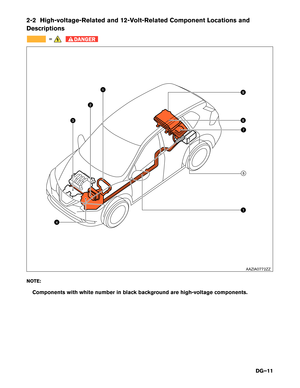
DANGER
• Failure to properly shut down the high-voltage electrical system before the
Dismantling Procedures are performed will result in serious injury or death from
electrical shock. To prevent serious injury or death, NEVER touch high-voltage
harnesses or components without always wearing appropriate Personal Protective
Equipment (PPE) . PPE must always be worn when touching or working on high-
voltage components.
• If it is necessary to touch any of the high-voltage harnesses or components you
must
always wear appropriate PPE to avoid electrical shock. PPE must always be worn
when touching or working on high-voltage components. Shut down the high-voltage
system by following the steps outlined in 3-4.1 High-voltage System Shut-Down
Procedure
(DG–22) . Wait approximately ten (10) minutes for complete discharge of the
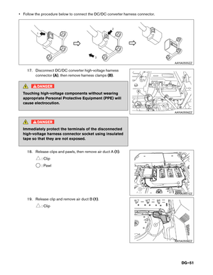
high-voltage
capacitor after the high-voltage system has been shut down. • NEVER assume the Rogue HYBRID is shut OFF simply because it is quiet.
•
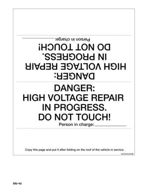
If it becomes necessary for the dismantler to leave the vehicle, place a “DANGER” sign
[for example, refer to 5. Storing the Vehicle (DG–41) on the vehicle to alert other people
that
the vehicle contains a high-voltage battery.
• If the READY indicator is ON the high-voltage system is active.
•
If possible, be sure to check the READY indicator on the instrument cluster and
verify
that the READY indicator is OFF and the high-voltage system is stopped.
DG–17
Page 18 of 53
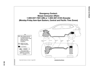
: Up to 1,000V For protection from high-
voltage electrical shock.
Insulated gloves Insulated shoes
—")
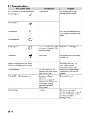
3-1 Preparation Items
Preparation Items
SpecificationPurpose
PPE
(personal protective equipment): Up to 1,000V For protection from high-
voltage electrical shock.
Insulated gloves Insulated shoes
—
Safety
shield —
T
o protect eyes when around
high-voltage components and
wiring.
Safety Glasses Leather gloves Must be able to fasten tight
around
the wrist (worn over
insulated gloves) . To protect insulated gloves.
Wrenches Size:10mm
To remove the 12-volt battery
terminal
bolt.
Solvent resistant protection gloves
Solvent resistant protection shoes —To utilize in the event of a
high-voltage battery
electrolytic solution leak.
Absorbent pad The same pad used for
internal combustion engine
fluids can be used. To absorb any high-voltage
battery electrolytic solution
leakage.
Standard fire fighting equipment Standard fire fighting
equipment.
Depending on type of
fire (vehicle or battery) use
standard fire fighting
equipment (water or
extinguisher) . To extinguish a fire.
Insulated tape InsulatingTo cover any damaged
harnesses to protect from and
prevent electrical shock. Tape
should cover all bare or
damaged wire.
DG–18
Page 19 of 53
 and Insulated Tools
3-2.1
Personal Protective Equipment (PPE) Protective Wear Control
Perform an inspection of the Personal Protective Equipment (PPE) items bef")
3-2 Personal Protective Equipment (PPE) and Insulated Tools
3-2.1
Personal Protective Equipment (PPE) Protective Wear Control
Perform an inspection of the Personal Protective Equipment (PPE) items before beginning work. Do not use
any damaged PPE items.
3-2.2 Daily Inspection
This inspection is performed before and after use. The worker who will be using the items should perform
the inspection and check for deterioration and damage. • Insulated rubber gloves should be inspected for scratches, holes and tears. (Visual check and airleakage test)
• Insulated safety boots should be inspected for holes, damage, nails, metal pieces, wear or other problems on the soles. (Visual check)
• Insulated rubber sheet should be inspected for tears. (Visual check)
3-2.3 Insulated Tools
When performing work at locations where high-voltage is applied (such as terminals) , use insulated tools
meeting 1,000V/300A specifications.
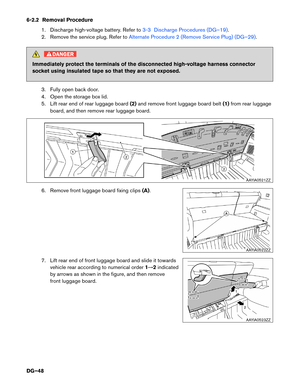
3-3 Discharge Procedures DANGER
Do not perform this procedure if the battery is damaged. If you are unsure of battery
damage,
use extreme caution and wear appropriate Personal Protective Equipment (PPE) .
High-voltage battery discharging must take place before dismantling. Sufficient discharging can be
achieved by following these steps. 1. Place the shift selector into the Park (P) position.
2. Apply the parking brake.
3. Set wheel chocks to ensure the vehicle is completely immobilized.
4. Fasten the driver seat belt and close the driver door.
5. Apply foot brake and press the ignition switch to turn the system ON. Confirm READY indicator in instrument cluster turns ON.
a.
If the engine starts, leave the engine running until reaching normal operating temperature
and the idling stops. It may take more than 10 minutes for complete engine warm up and
idling to stop.
b. If the engine is at normal operating temperature and does NOT start, move on to next step.
DG–19
Page 20 of 53
 position wh")
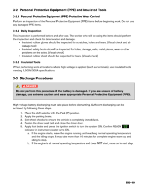
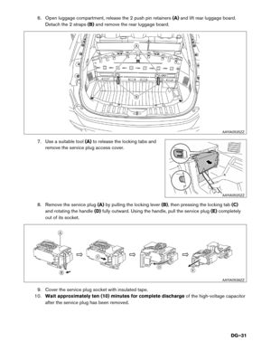
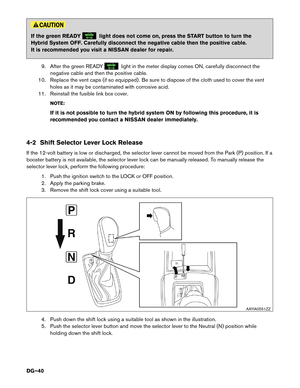
6. Remove the shift lock cover using a suitable tool.
7.
Push down the shift lock as shown in the illustration.
8. Push the shift selector button and move the shift selector to Neutral (N) position while holding down the shift lock.
NOTE:
DO NOT press accelerator or foot brake after moving the shift selector to the Neutral (N)
position. Otherwise high-voltage battery will start to be charged.
NOTE:
The engine must not be running at this time. If the engine has restarted, repeat the
previous steps.
9. Release the parking brake. The READY indicator should remain ON and the engine should
not
be running.
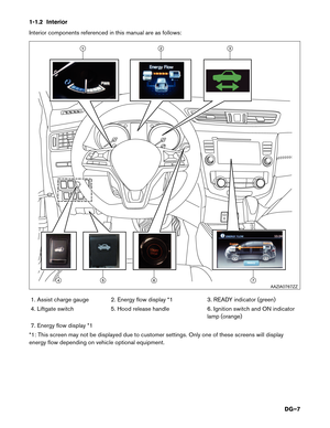
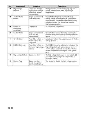
10.
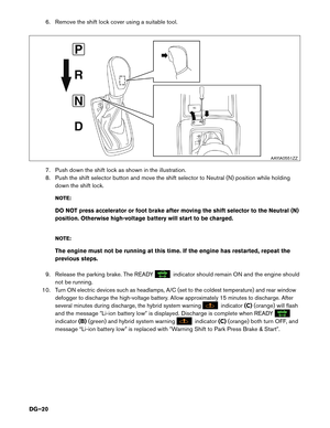
Turn ON electric devices such as headlamps, A/C (set to the coldest temperature) and rear window
defogger to discharge the high-voltage battery. Allow approximately 15 minutes to discharge. After
several minutes during discharge, the hybrid system warning indicator
(C)(orange)
will flash
and the message �Li-ion battery low� is displayed. Discharge is complete when READY indicator
(B)(green)
and hybrid system warning indicator
(C)(orange) both turn OFF, and
message “Li-ion battery low” is replaced with �Warning Shift to Park Press Brake & Start�. AAYIA0551ZZ
DG–20
Page 21 of 53
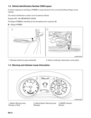
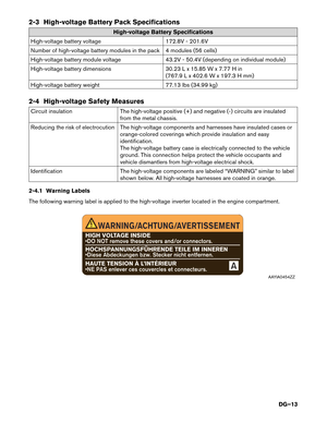
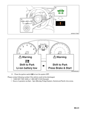
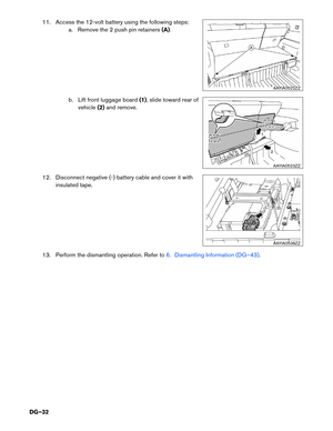
11. Press the ignition switch
(A)to turn the system OFF.
Please contact following number if the vehicle could not be discharged. • 1-800-647-7261 (US) or 1-800-387-0122 (Canada)
• Hours of operation are 8am - 5pm (Monday-Friday) Eastern, Central and Pacific time zones. AAYIA0177GB
AAYIA0552ZZ
DG–21
Page 22 of 53

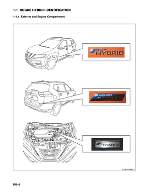
3-4 How to Handle a Damaged Vehicle
3-4.1
High-voltage System Shut-Down Procedure
Any of the following procedures can shut down the high-voltage system. The dismantling operation can only
begin after shutting down the high-voltage system. If the vehicle is heavily damaged, for example the high-
voltage battery is deformed, broken or cracked, appropriate PPE must always be used and the high-voltage
battery and high-voltage components must not be touched. DANGER
• Failure to properly shut down the high-voltage system before the dismantling
procedures
are performed will result in serious injury or death from electrical shock. To
prevent serious injury or death, NEVER touch high-voltage harnesses or components
without always wearing appropriate Personal Protective Equipment (PPE) . Appropriate
PPE must always be worn when touching or working on high-voltage components.
• When contact with high-voltage components or high-voltage harnesses is
unavoidable,
or when there is risk of such contact, you must always wear appropriate
PPE. PPE must always be worn when touching or working on high-voltage
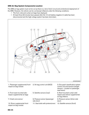
components. • The vehicle contains parts that contain powerful magnets. If a person who is wearing
a
pacemaker or other medical device is close to these parts, the medical device may be
affected by the magnets. Such persons must not perform work on the vehicle.
• Be sure to verify that the READY indicator is off (if possible) , and the high-voltage
system
is stopped.
• After the high-voltage system is shut down, please wait approximately ten (10) minutes for complete discharge of the high-voltage capacitor. While waiting, do not operate any
vehicle functions.
• After shutting down the high-voltage system and removing the 12-volt battery negative (-) terminal, wait at least three (3) minutes to discharge the air bag capacitor. Even though
the 12-volt battery negative (-) is disconnected, the Supplemental Restraint System (SRS)
air bag maintains voltage at least three (3) minutes. During this time, there is a possibility
of sudden SRS air bag inflation due to harness short circuit or damage and it may cause
serious injuries.
• The 12V system will remain active even after the 12-volt battery negative (-) terminal is removed while the high-voltage system is active. This is because the charging system
will not shut down and power will be supplied to the 12V system and high-voltage system
continuously.
Before disconnecting the 12-volt battery terminal, if necessary, lower the windows, adjust the steering
column, adjust the seats, unlock the doors, open the liftgate, etc. as required. Once the 12-volt battery is
disconnected, power controls will not operate.
DG–22
Page 23 of 53

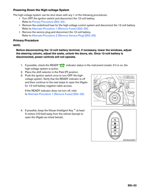
Powering Down the High-voltage System
The
high-voltage system can be shut down with any 1 of the following procedures:• Turn OFF the ignition switch and disconnect the 12-volt battery. Refer to Primary Procedure (DG–23) .
•
Remove the underhood fuse for the high-voltage control system and disconnect the 12-volt battery.
Refer to Alternate Procedure 1 (Remove Fuses) (DG–26).
•
Remove the service plug and disconnect the 12-volt battery.
Refer to Alternate Procedure 2 (Remove Service Plug) (DG–29).
Primary
Procedure
NOTE:
Before disconnecting the 12-volt battery terminal, if necessary, lower the windows, adjust
the steering column, adjust the seats, unlock the doors, etc. Once 12-volt battery is
disconnected, power controls will not operate.
1. If possible, check the READY indicator status in the instrument cluster. If it is on, the
high-voltage
system is active.
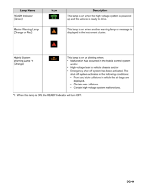
2. Place the shift selector in the Park (P) position.
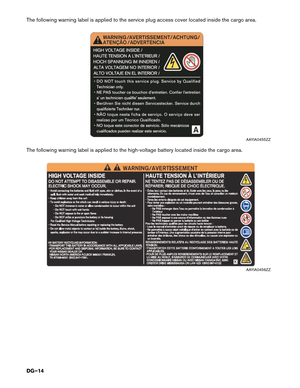
3. Push the ignition switch once to turn OFF the high- voltage system. Verify that the READY indicator is off
and then continue to the next steps to open the liftgate
for 12-volt battery negative cable access.
If the READY indicator does not turn off, refer
toAlternate Procedure 1 (Remove Fuses) (DG–26).
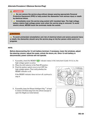
4.
If possible, keep the Nissan Intelligent Key
®at least
5 meters (16 feet) away from the vehicle (except to
open the liftgate as noted below) . AAYIA0516ZZ
HOLD
AAYIA0446ZZ
DG–23
Page 24 of 53
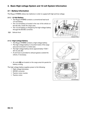
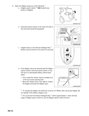
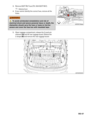
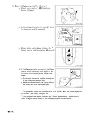
5. Open the liftgate using any of the following*1:
a. Liftgate opener switch*2(A) (located near
bottom of liftgate) .
b. Instrument panel switch on the lower LH side of the instrument panel (If equipped) .
c. Liftgate button on the Nissan Intelligent Key
®
(button must be held for more than 0.5 second) .
d. If the liftgate cannot be opened with the liftgate opener switch, instrument panel switch, or key
fob due to a discharged battery, follow these
steps:
• From inside the vehicle, Insert a suitable toolin the top access opening hole.
• Move the release lever to the right to unlatch the liftgate and push the liftgate open.
*1: To operate the liftgate, the shift lever must be in P (Park) . Also, the power liftgate will
not operate if the battery voltage is low.
*2: You must have the Nissan Intelligent Key®within approximately 1 meter (3 feet)
range of liftgate opener switch to use the liftgate opener switch function. AAYIA0517ZZ
AAYIA0518ZZ
AAYIA0519ZZ
AAYIA0520ZZ
DG–24


to turn the system OFF.
Please contact following number if the vehicle could not be discharged. • 1-800-647-7261 (US) or 1-800-387-0122 (Canada)
• Hours of operati")
 (located near
bottom of liftgate) .
b. Instrument panel switch on the lower LH side of the instrument panel (If equipp")