Page 33 of 53

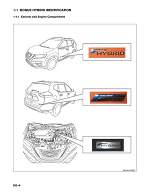
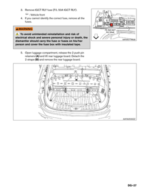
3-4.2 Cutting the Vehicle Body
DANGER
• Do not cut into high-voltage related areas to avoid severe personal injury or death.
• Do not cut into the high-voltage battery to avoid severe personal injury or death.
• When removing parts, NEVER touch the high-voltage parts or the insides of the
exposed orange-colored high-voltage cables to avoid severe personal injury or
death. Appropriate Personal Protective Equipment (PPE) must always be worn when
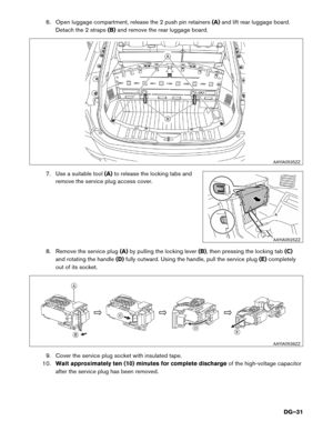
touching or working on high-voltage components. To avoid unintended reinstallation and risk of electrical shock and severe personal injury or
death,
the dismantler should carry the fuses or service plug on his/her person while work
is in progress. Do not cut air bag parts to avoid unintended deployment of the air bags and the risk of
severe
personal injury or death.
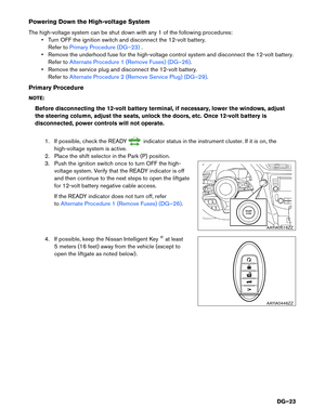
If approximately (10) minutes have passed since the dismantler shut down the high-voltage system [refer
to 3-4.1 High-voltage System Shut-Down Procedure (DG–22)], then the dismantler can cut the vehicle
except
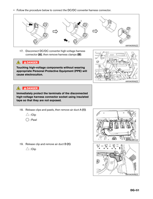
for the high-voltage battery. DO NOT cut the high-voltage battery due to possible electrocution risk and electrolyte solution
leakage.
DG–33
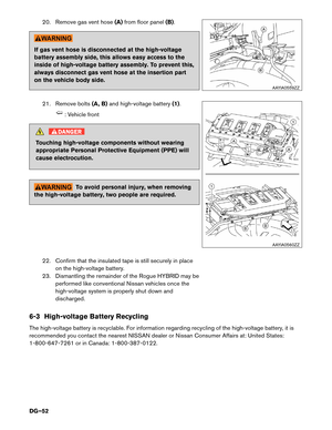
Page 34 of 53

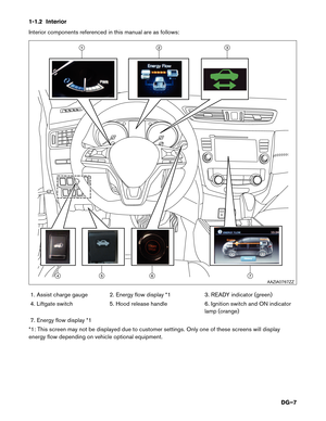
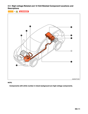
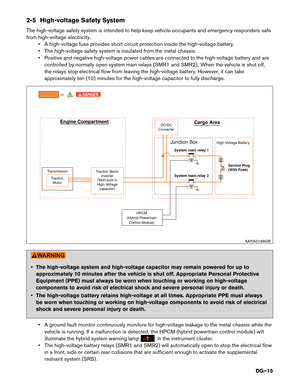
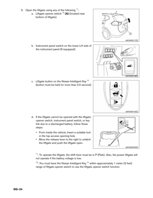
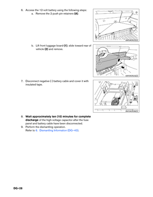
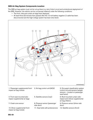
SRS Air Bag System Components Location
The
SRS air bag system must not be cut as there is a risk of short circuit and unintentional deployment of
the SRS. However, the vehicle can be cut (except inflators) under the following conditions: • The front, side and curtain air bags have deployed.
• At least three (3) minutes have passed after the 12-volt battery negative (-) cable has beendisconnected and the high-voltage system has been shut down.
1. Passenger supplemental front-
impact air bag module 2. Air bag control unit (ACU) 3. Occupant classification system
control unit and sensors (weight
sensors – located on passenger
seat frame)
4. Front seat-mounted side-
impact supplemental air bags 5. Satellite sensors (rear) 6. Roof-mounted curtain side-
impact and rollover supplemental
air bag inflators
7. Crash zone sensor 8. Pressure sensor (passenger
side door) 9. Pressure sensor (driver side
door)
10. Driver supplemental front-
impact air bag module 11. Seat belts with pretensioners 12. Satellite sensors (front) AAYIA0546ZZ
DG–34
Page 35 of 53
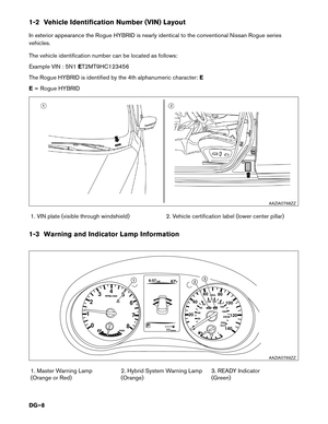
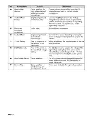
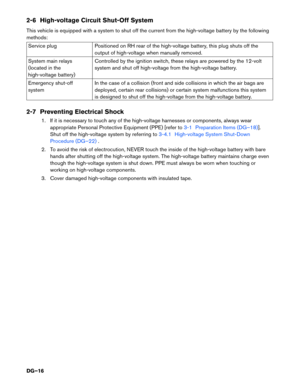
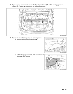
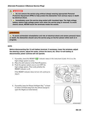
Vehicle Cut Sheet
AAYIA0547ZZ
DG–35
Page 36 of 53
 will result in serious
injury")
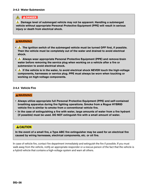
3-4.3 Water Submersion
DANGER
Damage level of submerged vehicle may not be apparent. Handling a submerged
vehicle without appropriate Personal Protective Equipment (PPE) will result in serious
injury or death from electrical shock. • The ignition switch of the submerged vehicle must be turned OFF first, if possible.
Then
the vehicle must be completely out of the water and drained to avoid electrical
shock.
• Always wear appropriate Personal Protective Equipment (PPE) and remove/drain
water
before removing the service plug when working on a vehicle after a fire or
submersion to avoid electrical shock.
• If the vehicle is in the water, to avoid electrical shock NEVER touch the high-voltage
components,
harnesses or service plug. PPE must always be worn when touching or
working on high-voltage components.
3-4.4 Vehicle Fire • Always utilize appropriate full Personal Protective Equipment (PPE) and self-contained
breathing
apparatus during fire fighting operations. Smoke from a Rogue HYBRID
vehicle fire is similar to smoke from a conventional vehicle fire.
• In the case of extinguishing a fire with water, large amounts of water from a fire hydrant (if possible) must be used. DO NOT extinguish fire with a small amount of water. In the event of a small fire, a Type ABC fire extinguisher may be used for an electrical fire
caused
by wiring harnesses, electrical components, etc. or oil fire.
In case of vehicle fire, contact fire department immediately and extinguish the fire if possible. If you must
walk away from the vehicle, notify an appropriate responder or a rescue person of the fact that the vehicle is
a hybrid vehicle that contains a high-voltage system and warn all others.
DG–36
Page 37 of 53

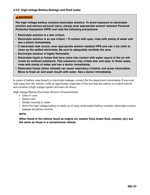
3-4.5 High-voltage Battery Damage and Fluid Leaks
The high-voltage battery contains electrolyte solution. To avoid exposure to electrolyte
solution
and serious personal injury, always wear appropriate solvent resistant Personal
Protective Equipment (PPE) and read the following precautions:
• Electrolyte solution is a skin irritant.
• Electrolyte solution is an eye irritant – If contact with eyes, rinse with plenty of water and see a doctor immediately.
• If electrolyte leak occurs, wear appropriate solvent resistant PPE and use a dry cloth to clean up the spilled electrolyte. Be sure to adequately ventilate the area.
• Electrolyte solution is highly flammable.
• Electrolyte liquid or fumes that have come into contact with water vapors in the air will create an oxidized substance. This substance may irritate skin and eyes. In these cases,
rinse with plenty of water and see a doctor immediately.
• Electrolyte fumes (when inhaled) can cause respiratory irritation and acute intoxication. Move to fresh air and wash mouth with water. See a doctor immediately.
In cases of battery case breach or electrolyte leakage, contact the fire department immediately. If you must
walk away from the vehicle, notify an appropriate responder of the fact that the vehicle is a hybrid vehicle
and contains a high-voltage system and warn all others.
High-voltage Battery Electrolyte Solution Characteristics: • Clear in color
• Sweet odor
• Similar viscosity to water
• Since the high-voltage battery is made up of many small sealed battery modules, electrolyte solutionleakage should be minimal.
NOTE:
Other fluids in the vehicle (such as engine oil, washer fluid, brake fluid, coolant, etc.) are
the same as those in a conventional vehicle.
DG–37
Page 38 of 53

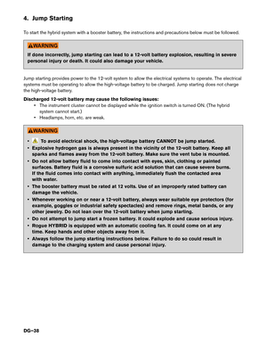
4. Jump Starting
T
o start the hybrid system with a booster battery, the instructions and precautions below must be followed. If done incorrectly, jump starting can lead to a 12-volt battery explosion, resulting in severe
personal
injury or death. It could also damage your vehicle.
Jump starting provides power to the 12-volt system to allow the electrical systems to operate. The electrical
systems must be operating to allow the high-voltage battery to be charged. Jump starting does not charge
the high-voltage battery.
Discharged 12-volt battery may cause the following issues: • The instrument cluster cannot be displayed while the ignition switch is turned ON. (The hybridsystem cannot start.)
• Headlamps, horn, etc. are weak. • To avoid electrical shock, the high-voltage battery CANNOT be jump started.
•
Explosive hydrogen gas is always present in the vicinity of the 12-volt battery. Keep all
sparks and flames away from the 12-volt battery. Make sure the vent tube is mounted.
• Do not allow battery fluid to come into contact with eyes, skin, clothing or painted surfaces. Battery fluid is a corrosive sulfuric acid solution that can cause severe burns.
If the fluid comes into contact with anything, immediately flush the contacted area
with water.
• The booster battery must be rated at 12 volts. Use of an improperly rated battery can damage the vehicle.
• Whenever working on or near a 12-volt battery, always wear suitable eye protectors (for example, goggles or industrial safety spectacles) and remove rings, metal bands, or any
other jewelry. Do not lean over the 12-volt battery when jump starting.
• Do not attempt to jump start a frozen battery. It could explode and cause serious injury.
• Rogue HYBRID is equipped with an automatic cooling fan. It could come on at any time. Keep hands and other objects away from it.
• Always follow the jump starting instructions below. Failure to do so could result in damage to the charging system and cause personal injury.
DG–38
Page 39 of 53

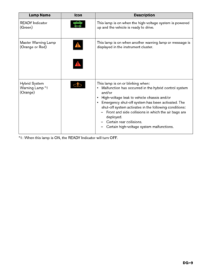
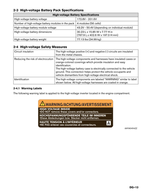
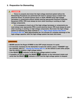
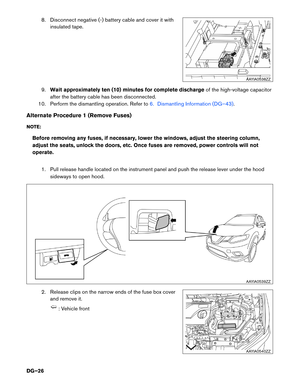
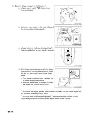
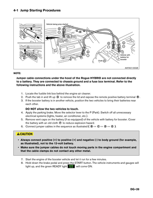
4-1 Jump Starting Procedures
NO
TE:
Jumper cable connections under the hood of the Rogue HYBRID are not connected directly
to a battery. They are connected to chassis ground and a fuse box terminal. Refer to the
following instructions and the above illustration.
1. Locate the fusible link box behind the engine air cleaner.
2. Push the tab in and lift up ○A
to remove the lid and expose the remote positive battery terminal
○B
.
3. If the booster battery is in another vehicle, position the two vehicles to bring their batteries near each other.
DO NOT allow the two vehicles to touch.
4. Apply the parking brake. Move the selector lever to the P (Park) . Switch off all unnecessary electrical systems (lights, heater, air conditioner, etc.) .
5. Remove vent caps on the battery (if so equipped) of the vehicle with battery for booster. Cover the battery with an old cloth ○F
to reduce explosion hazard.
6. Connect jumper cables in the sequence as illustrated (
○B
�
○C
�
○D
�
○E
). • Always connect positive (+) to positive (+) and negative (-) to body ground (for example,
as
illustrated) , not to the 12-volt battery.
• Make sure the jumper cables do not touch moving parts in the engine compartment and that the cable clamps do not contact any other metal.
7. Start the engine of the booster vehicle and let it run for a few minutes.
8. Hold down the brake pedal and press the START button. The vehicle instruments and gauges will light up, and the green READY light will come ON.A
B
+
E
F
-
D
-
C
+
B
Cloth
Vehicle being jump started
Vehicle with
battery for
boosterAAYIA0133GB
DG–39
Page 40 of 53

If the green READY light does not come on, press the START button to turn the
Hybrid
System OFF. Carefully disconnect the negative cable then the positive cable.
It is recommended you visit a NISSAN dealer for repair.
9. After the green READY light in the meter display comes ON, carefully disconnect the
negative
cable and then the positive cable.
10. Replace the vent caps (if so equipped) . Be sure to dispose of the cloth used to cover the vent holes as it may be contaminated with corrosive acid.
11. Reinstall the fusible link box cover.
NOTE:
If it is not possible to turn the hybrid system ON by following this procedure, it is
recommended you contact a NISSAN dealer immediately.
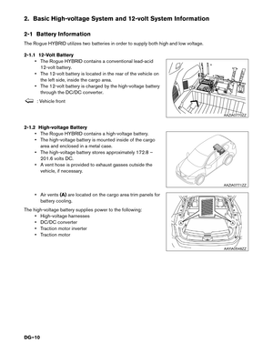
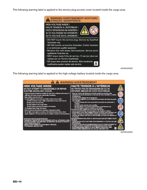
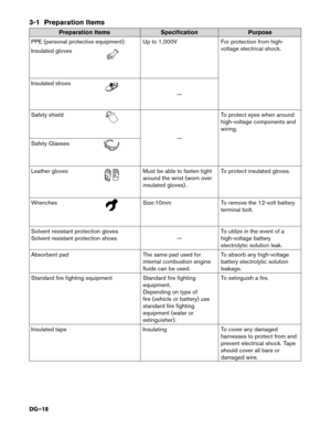
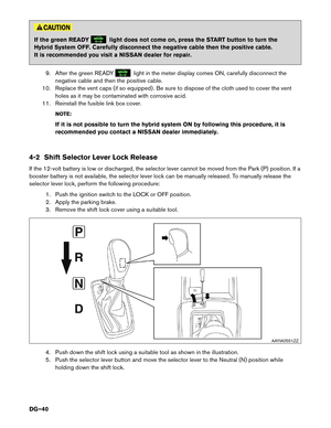
4-2 Shift Selector Lever Lock Release
If the 12-volt battery is low or discharged, the selector lever cannot be moved from the Park (P) position. If a
booster battery is not available, the selector lever lock can be manually released. To manually release the
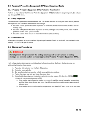
selector lever lock, perform the following procedure: 1. Push the ignition switch to the LOCK or OFF position.
2. Apply the parking brake.
3. Remove the shift lock cover using a suitable tool.
4. Push down the shift lock using a suitable tool as shown in the illustration.
5. Push the selector lever button and move the selector lever to the Neutral (N) position whileholding down the shift lock. AAYIA0551ZZ
DG–40