Page 273 of 318

XTo open:turn top rotary catch :clockwise
and bottom rotary catch :counter-clock-
wise.
XRemove cover ;.
XTo close:insert cover ;.
XTurn top rotary catch :counter-clockwise
and bottom rotary catch :clockwise.
XFold down the rear seat.
Removing/stowing vehicle tool kit and
jack
Depending on the equipment version of the vehi-
cle, the vehicle tool kit and the jack are stowed
either in a stowage tray or in a tool holder with a
cover.
Stowage compartment with stowage tray
XTo remove tools: open the stowage com-
partment.
XOpen clamping strap =and remove jack ?
by pulling it upwards at an angle from the
stowage tray compartment.
XRemove vehicle tool bag Aupwards from the
stowage tray compartment.
XTo stow tools: insert vehicle tool bag Ainto
the front compartment of the stowage tray.
XBefore stowing, wind jack ?to the fully
closed position and place it so that the hand
wheel is facing downwards and the plate is
facing inwards at an angle.
XInsert jack ?into the back compartment of
the stowage tray.
XPress jack ?into the upper holder and fasten
clamping strap =.
The jack is secured.
XClose the stowage compartment.
Stowage compartment with tool holder
XTo remove tools: open the stowage com-
partment.
XRemove clamping strap C.
XRemove tool holder cover B.
XCarefully pull the tool kit and jack out of the
stowage compartment. Lift the jack slightly
before removing it and turn it to a diagonal
position in the stowage compartment.
XTo stow tools:before stowing, wind the jack
to the fully closed position and place it so that
the hand wheel is facing forwards and the
plate is facing inwards.
XPlace the jack and vehicle tool kit into the tool holder.
XReplace tool holder cover B.
XTighten clamping strapC.
XClose the stowage compartment.
Stowage space in the cargo compart-
ment
Tool holder in the cargo compartment
Tool holder in the cargo compartment on the right-
hand side of the vehicle
Where will I find...?271
Breakdown assis tance
Page 274 of 318

XTo remove tools:release clamping strap ;.
XRemove tool holder cover :
XCarefully pull the tool kit and jack out of the
tool holder.
XTo stow tools:before stowing, wind the jack
to the fully closed position and place it so that
the hand wheel is facing forwards and the
plate is facing inwards.
XPlace the jack and vehicle tool kit into the tool
holder.
XReplace tool holder cover :.
XTighten clamping strap;.
Separate holder for jack
Holder for the jack in the cargo compartment on
the right-hand side of the vehicle
The vehicle tool kit or tire-changing tools are in
the seat base of the left front seat (Ypage 270).
XTo remove the jack:release clamping
strap :.
XPull jack ;out of the upper holder and from
the lower fixture =.
XTo stow the jack: before stowing, wind the
jack to the fully closed position and place it so
that the hand wheel is facing forwards and the plate is facing inwards.
XPlace jack ;onto lower fixture =.
XPress jack;into the upper holder and fasten
clamping strap :.
The jack is secured.
First-aid kit
Removing the first-aid kit
The first-aid kit is located in the stowage com-
partment in the front-passenger door.
iCheck the expiration date on the first-aid kit
at least once a year. Replace any expired or
missing contents.
Observe the legal requirements of the country
in which you are currently driving.
Flat tire
In your vehicle, you will find a sticker with the
Mercedes-Benz Service24h telephone number,
e.g. on the B-pillar on the driver's side.
For vehicles with a spare wheel, information on
breakdown assistance in the event of a flat tire
can be found under "Wheels and tires"
(
Ypage 296).
Jump-starting
Important safety notes
GWARNING
During charging and jump-starting, explosive
gases can escape from the battery. There is a risk of an explosion.
Particularly avoid fire, open flames, creating
sparks and smoking. Ensure there is sufficient
ventilation while charging and jump-starting.
Do not lean over a battery.
GWARNING
Battery acid is caustic. There is a risk of injury.
Avoid contact with skin, eyes or clothing. Do
not inhale any battery gases. Do not lean over
the battery. Keep children away from batter-
ies. Wash away battery acid immediately with
plenty of clean water and seek medical atten-
tion.
GWARNING
A discharged battery can freeze at tempera-
tures below freezing point. When jump-start-
ing the vehicle or charging the battery, gases can escape from the battery. There is a risk of
an explosion.
Allow the frozen battery to thaw out before
charging it or jump-starting.
272Jump-starting
Breakdo wn assis tance
Page 275 of 318

!Vehicles with a gasoline engine:avoid
repeated and lengthy starting attempts. Oth-
erwise, the catalytic converter could be dam-
aged by non-combusted fuel.
If the indicator and warning lamps in the instru-
ment cluster do not light up at low tempera-
tures, the discharged battery may have frozen.
In this case you may neither charge the battery
nor jump-start the vehicle. The service life of a
thawed battery may be shorter. Start-up behav-
ior may deteriorate, in particular at low temper-
atures. Have the thawed battery checked at a
qualified specialist workshop.
Do not use a rapid charging device to start the
vehicle. If your vehicle's battery is discharged,
the engine can be jump-started from another
vehicle or from a donor battery using jumper
cables. For this purpose, the vehicle has a jump-
starting connection point in the engine com-
partment.
When jump-starting, observe the following
points:
RThe battery is not accessible in all vehicles. If
the other vehicle's battery is not accessible,
jump-start the vehicle using a donor battery
or a jump-starting device.
RYou may only jump-start the vehicle when the
engine and exhaust system are cold.
Rdo not start the engine if the battery is frozen.
Let the battery thaw first.
Rjump-starting may only be performed from
batteries with a nominal voltage of 12 V.
Ronly use jumper cables that have a sufficient
cross-section and insulated terminal clamps.
Rif the battery is fully discharged, attach the
battery of another vehicle for a few minutes
before attempting to start. This charges the
empty battery a little.
Rmake sure that the two vehicles do not touch.
Make sure that:
Rthe jumper cables are not damaged.
Rbare parts of the terminal clamps do not come into contact with other metal parts while the
jumper cables are connected to the battery.
Rthe jumper cables cannot come into contact
with parts such as the V-belt pulley or the fan.
These parts move when the engine is started
and while it is running.
Jumper cables and further information regarding
jump starting can be obtained at any qualified
specialist workshop.
Before connecting the jumper cables
XApply the parking brake.
XShift the transmission to position P.
XSwitch off all electrical consumers, e.g. audio
equipment, blower.
XTurn the key to position 0in the ignition lock
and remove it.
XOpen the hood (Ypage 251).
Connecting the jumper cable
XPush contact protection cover :of the jump-
starting connection point backwards against
the spring force as far as it will go.
The jump-starting connection point is visible.
Terminal connecting planXRemove the cover from positive terminal =
of the donor vehicle's battery.
XConnect the positive terminal clamp of the
jumper cable to positive terminal =of the
donor vehicle's battery, and then to positive
terminal Aof the jump-starting connection
point.
XRun the donor vehicle's engine at idling
speed.
Jump-starting273
Breakdown assistance
Z
Page 276 of 318

XConnect the negative terminal clamp of the
jumper cable to negative terminal;of the
donor veh icle's battery, and then to earth
contact ?of your own veh icle.
XInsert the key into the ignition lock and start
the engine.
You can now switch electrical consumers
back on except the lighting system.
XBefore disconnecting the jumper cables, let
the engine run for several minutes.
XDisconnect the negative terminal of the
jumper cable from earth contact ?and then
from negative terminal ;of the donor veh i-
cle's battery.
XDisconnect the positive terminal clamp of the
jumper cable from positive terminal Aon the
jump-starting connection point, and then
from positive terminal =of the donor veh i-
cle's battery.
Contact protection cover :isautomatically
returned forwards to its original position by
the spring force and the jump-starting con-
nection pointis closed.
XPosition the cover on positive terminal =of
the donor veh icle's battery.
You can now switch on the lighting system.
XHave the battery checked at a qualified spe-
cialist workshop.
Tow-starting and towing away
Important safety notes
GWAR NING
Functions relevant to safety are restricted or
no longer availab leif:
Rthe engine isnot running.
Rthe brake system or the power steering is
malfunctioning.
Rthere isa malfunction inthe voltage supply
or the veh icle's electrical system.
If your veh icle is bein g towed, much more
force may benecessary to steer or brake.
There isa risk of an acc ident.
In such cases, use a tow bar. Before to wing,
make sure that the steering moves freely.
GWARNING
You can no longer steer the vehicle ifthe
steering wheel lock has been engaged. There
is a risk of an accident.
Alwa ysswit ch off the ignition when to wingthe
vehicle with a tow cable or a tow bar.
GWARNING
When to wingor tow-starting another vehicle
and its weight isgreater than the permissible
gross weight of your vehicle, the:
Rthe to wingeye could detach itself
Rthe vehicle /trailer combination could roll-
over.
There is a risk of an accident.
When towing or tow-starting another vehicle,
its weight should not be greater than the per- missible gross weight of your vehicle.
In formation on the gross vehicle weight can be
found on the vehicle identification plate
(
Ypage 303).
!Secure the tow rope or tow bar to the to wing
eye or trailer tow hitch only. Otherwise, the
vehicle could become damaged.
!Do not use the to wingeye for recovery, this
could damage the vehicle. If indoubt, recover
the vehicle with a crane.
!Drive slowly and smoothly when to wing.
Excessive tractive power could otherwise
damage the vehicles.
!Shift the automatic transmission to Nand
do not open the driver's or front passenger's
door during to wing. The automatic transmis-
sion may otherwise shift to position P,whic h
could damage the transmission.
!The vehicle can be towed a maximum of
30 miles (50km ).The to wingspeed of 30 mph
(50 km/h) must not be exceeded.
If the vehicle has to betowed more than
30 mile
s(50k
m) ,the entire vehicl emust be
raised and transported.
When towing away, you must observe the legal
requirements for the country in which you are
currently driving.
It is better to have the vehicle transported than
to have it towed.
274Tow-starting and towing away
Breakdown assistance
Page 277 of 318

Have the vehicle transported on a transporter or
trailer if it has transmission damage.
When towing, the automatic transmission must
be in position N. If the automatic transmission
cannot be shifted to position N, have the vehicle
transported on a transporter or trailer.
The battery must be connected and charged.
Otherwise, you:
Rcannot turn the key to position 2in the igni-
tion lock
Rcannot shift the transmission to position N
Before the vehicle is towed, switch off the auto-
matic locking feature (
Ypage 74). You could
otherwise lock yourself out of the vehicle when
pushing or towing away the vehicle.
Installing/removing the towing eye
The fixture for the front towing eye is located in the
bumper.
The rear towing eye is located under the bumper.
If you tow or tow-start a vehicle, attach the tow-
ing device to rear towing eye ;.
If your vehicle is equipped with a trailer tow
hitch, attach the towing device to the trailer tow
hitch (
Ypage 163). Installing the front towing eye
XTake the towing eye and screwdriver from the
vehicle tool kit (Ypage 270).
XPress the arrow on the cover
:and remove
cover :from the opening.
You will see the fixture for the towing eye.
XScrew in the towing eye clockwise to the stop.
XInsert the screwdriver into the towing eye and
tighten the towing eye.
XStow the screwdriver in the vehicle tool kit
(Ypage 270).
Removing the front towing eye
XRemove the screwdriver from the vehicle tool
kit (Ypage 270).
XInsert the screwdriver into the towing eye and
turn the screwdriver counter-clockwise.
XUnscrew the towing eye.
XInsert cover :with the lug at the top and
press it in at the bottom until it engages.
XStow the towing eye and the screwdriver with
the vehicle tool kit (Ypage 270).
Towing with the rear axle raised
!
Vehicles with automatic transmission must
not be towed with the rear axle raised. The
vehicle/trailer combination may otherwise
swerve or even roll over.
!The ignition must be switched off if the vehi-
cle is being towed with the front or rear axle
raised. Otherwise, ESP
®may intervene and
damage the brake system.
XSwitch on the hazard warning lamps
(Ypage 96).
XTurn the front wheels to the straight-ahead
position.
XRelease the parking brake.
XIf necessary, turn the key to position 0in the
ignition lock and remove it.
XTake the key with you when leaving the vehi-
cle.
XDo not exceed the towing speed of 30 mph
(50 km/h).
Please observe the important safety instruc-
tions when towing your vehicle with the rear axle
raised (
Ypage 274).
Tow-starting and towing away275
Breakdown assistance
Z
Page 278 of 318

Towing the vehicle with both axles on
the ground
Important safety notes
GWARNING
You can no longer steer the vehicle if the
steering wheel lock has been engaged. There
is a risk of an accident.
Always switch off the ignition when towing the
vehicle with a tow cable or a tow bar.
!Do not exceed the towing speed of 30 mph
(50 km/h). You could otherwise damage the
transmission.
Please observe the important safety notes
before towing your vehicle (
Ypage 274).
Towing vehicles with automatic trans-
mission
XTurn the key to position 2in the ignition lock.
XDepress the brake pedal and keep it
depressed.
XShift the automatic transmission to position
N.
XLeave the key in position 2in the ignition lock.
XSwitch on the hazard warning lamps
(Ypage 96).
XRelease the parking brake.
XRelease the brake pedal.
XDo not exceed the towing speed of 30 mph
(50 km/h).
Recovering a vehicle that is stuck
!
When recovering a vehicle that has become
stuck, pull it as smoothly and evenly as pos-
sible. Excessive tractive power could damage
the vehicles.
If the drive wheels get trapped on loose or
muddy ground, recover the vehicle with the
utmost care. This is especially the case if the
vehicle is laden.
Never attempt to recover a vehicle with a trailer
attached.
Pull out the vehicle backwards, if possible, using
the tracks it made when it became stuck.
Transporting the vehicle
!
You may only secure the vehicle by the
wheels, not by parts of the vehicle such as
axle or steering components. Otherwise, the
vehicle could be damaged.
The towing eye or trailer tow hitch can be used
to pull the vehicle onto a trailer or transporter if
you wish to transport it.
XTurn the key to position 2in the ignition lock.
XShift the transmission to position N.
XRelease the parking brake.
If the vehicle is loaded:
XShift the transmission to position P.
XTurn the key to position 0in the ignition lock
and remove it.
XMake sure the parking brake is applied.
XLash down the vehicle.
Tow-starting (emergency engine
starting)
General notes
!Vehicles with automatic transmission must
not be tow-started. You could otherwise dam-
age the automatic transmission.
You can find information on jump-starting under
"Jump-starting“ (
Ypage 272).
Electrical fuses
The fuse allocation chart and important safety
information on the fuses can be found in the
"Fuse allocation chart" supplement.
276Electrical fuses
Breakdown assistance
Page 279 of 318

Useful information
This Operator's Manual describes all models as
well as standard and optional equipment of your
vehicle that were available at the time of going
to print. Country-specific variations are possi-
ble. Note that your vehicle may not be equipped
with all of the described functions. This also
applies to systems and functions relevant to
safety.
Read the information on qualified specialist
workshops (
Ypage 31).
Important safety notes
GWarning
A flat tire severely impairs the driving, steer-
ing and braking characteristics of the vehicle.
There is a risk of an accident.
do not drive with a flat tire. Immediately
replace the flat tire with your spare wheel, or
consult a qualified specialist workshop.
GWARNING
If wheels and tires of the wrong size are used, the wheel brakes or suspension components
may be damaged. There is a risk of an acci-
dent.
Always replace wheels and tires with those
that fulfill the specifications of the original
part.
When replacing wheels, make sure to use the
correct:
Rdesignation
Rmodel
When replacing tires, make sure to use the
correct:
Rdesignation
Rmanufacturer
Rmodel
Accessories that are not approved for your vehi-
cle by Mercedes-Benz or are not being used cor-
rectly can impair operating safety. Before purchasing and using non-approved
accessories, visit a qualified specialist work-
shop and inquire about:
Rsuitability
Rlegal stipulations
Rfactory recommendations
Information on the dimensions and types of
wheels and tires for your vehicle can be found
under "Wheel and tire combinations" .
Information on your vehicle's tire pressure can
be found:
Rin the Tire and Loading Information placard on
the B-pillar, driver's side
Rin the tire pressure table inside the fuel filler
flap (Ypage 281)
Runder "Tire pressure tables" (Ypage 288)
Runder "Tire pressure" (Ypage 280)
Modifications to the brake system or wheels are
not permitted. The use of a spacer and brake
dust shields is not permitted. This invalidates
the general operating permit for the vehicle.
Further information on wheels and tires can be
obtained at any qualified specialist workshop.
Operation
Information for a journey
If the vehicle is heavily laden, check the tire
pressures, and correct them, if necessary
(
Ypage 280).
While driving, pay attention to vibrations, noises
and unusual handling characteristics, e.g. pull-
ing to one side. This may indicate that the
wheels or tires are damaged. If you suspect that
a tire is defective, reduce your speed immedi-
ately. Stop the vehicle as soon as possible to
check the wheels and tires for damage. Hidden
tire damage could also be causing the unusual
handling characteristics. If you find no signs of
damage, have the tires and wheels checked at a
qualified specialist workshop.
When parking your vehicle, make sure that the
tires do not get deformed by the curb or other
obstacles. If it is necessary to drive over curbs,
speed humps or similar elevations, try to do so
slowly and not at a sharp angle. Otherwise, the
tires, particularly the sidewalls, can get dam-
aged.
Operation277
Wheels and tires
Z
Page 280 of 318

Regular wheel and tire checks
GWARNING
Damaged tires can cause tire inflation pres-
sure loss. As a result, you could lose control of
your vehicle. There is a risk of accident.
Check the tires regularly for signs of damage
and replace any damaged tires immediately.
Check the wheels and tires of your vehicle for
damage regularly, i.e. at least every two weeks,
as well as after driving off-road or on rough
roads. Damaged wheels can cause a loss of tire
pressure. Pay particular attention to damage
such as:
Rcuts in the tires
Rpunctures
Rtears in the tires
Rbulges on tires
Rdeformation or severe corrosion on wheels
Regularly check the tire tread depth and the
condition of the tread across the whole width of
the tire (
Ypage 278). If necessary, turn the
front wheels to full lock in order to inspect the
inner side of the tire surface.
All wheels must have a valve cap to protect the valve against dirt and moisture. Do not install
anything onto the valve other than the standard
valve cap or other valve caps approved for your vehicle by dealers listed on the inside of the
front cover. Do not install any other valve caps
or systems, e.g. tire pressure monitor systems.
Regularly check the pressure of all the tires,
particularly prior to long trips. Adjust the tire
pressure if ne
cessary (Ypage 280).
The service life of tires depends on various fac-
tors, including the following:
Rdriving style
Rtire pressure
Rmileage
Tire tread
GWARNING
Insufficient tire tread will reduce tire traction.
The tire is no longer able to dissipate water.
This means that on wet road surfaces, the risk
of hydroplaning increases, in particular where
speed is not adapted to suit the driving con-
ditions. There is a risk of accident.
If the tire pressure is too high or too low, tires may exhibit different levels of wear at differ-
ent locations on the tire tread. Thus, you
should regularly check the tread depth and
the condition of the tread across the entire
width of all tires.
Minimum tire tread depth for:
RSummer tires: âin (3 mm)
RM+S tires: ãin (4 mm)
For safety reasons, replace the tires before
the legally prescribed limit for the minimum
tire tread depth is reached.
Marker :shows the location where the bar
indicator (arrow) for tread wear is integrated
into the tire tread.
Tread wear indicators (TWIs) are required by
law. Six indicators are positioned over the tire
tread. They are visible once the tread depth is
approximately áin (1.6 mm). If this is the case,
the tire is so worn that it must be replaced.
Selecting, mounting and replacing
tires
ROnly mount tires and wheels of the same type
and make.
ROnly use wheels with tire sizes approved by
Mercedes-Benz.
ROnly mount tires of the correct size onto the
wheels.
RBreak in new tires at moderate speeds for the
first 65 miles (100 km).
278Operation
Wheels and tires
 1
1 2
2 3
3 4
4 5
5 6
6 7
7 8
8 9
9 10
10 11
11 12
12 13
13 14
14 15
15 16
16 17
17 18
18 19
19 20
20 21
21 22
22 23
23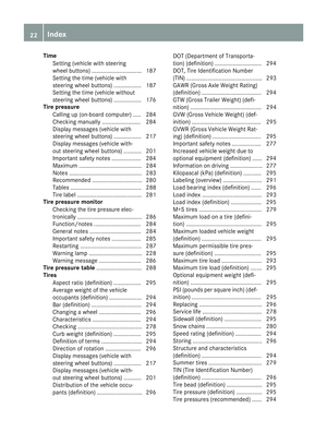 24
24 25
25 26
26 27
27 28
28 29
29 30
30 31
31 32
32 33
33 34
34 35
35 36
36 37
37 38
38 39
39 40
40 41
41 42
42 43
43 44
44 45
45 46
46 47
47 48
48 49
49 50
50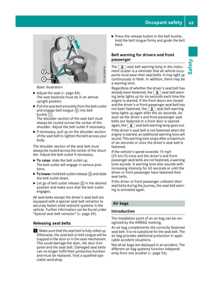 51
51 52
52 53
53 54
54 55
55 56
56 57
57 58
58 59
59 60
60 61
61 62
62 63
63 64
64 65
65 66
66 67
67 68
68 69
69 70
70 71
71 72
72 73
73 74
74 75
75 76
76 77
77 78
78 79
79 80
80 81
81 82
82 83
83 84
84 85
85 86
86 87
87 88
88 89
89 90
90 91
91 92
92 93
93 94
94 95
95 96
96 97
97 98
98 99
99 100
100 101
101 102
102 103
103 104
104 105
105 106
106 107
107 108
108 109
109 110
110 111
111 112
112 113
113 114
114 115
115 116
116 117
117 118
118 119
119 120
120 121
121 122
122 123
123 124
124 125
125 126
126 127
127 128
128 129
129 130
130 131
131 132
132 133
133 134
134 135
135 136
136 137
137 138
138 139
139 140
140 141
141 142
142 143
143 144
144 145
145 146
146 147
147 148
148 149
149 150
150 151
151 152
152 153
153 154
154 155
155 156
156 157
157 158
158 159
159 160
160 161
161 162
162 163
163 164
164 165
165 166
166 167
167 168
168 169
169 170
170 171
171 172
172 173
173 174
174 175
175 176
176 177
177 178
178 179
179 180
180 181
181 182
182 183
183 184
184 185
185 186
186 187
187 188
188 189
189 190
190 191
191 192
192 193
193 194
194 195
195 196
196 197
197 198
198 199
199 200
200 201
201 202
202 203
203 204
204 205
205 206
206 207
207 208
208 209
209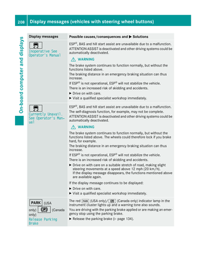 210
210 211
211 212
212 213
213 214
214 215
215 216
216 217
217 218
218 219
219 220
220 221
221 222
222 223
223 224
224 225
225 226
226 227
227 228
228 229
229 230
230 231
231 232
232 233
233 234
234 235
235 236
236 237
237 238
238 239
239 240
240 241
241 242
242 243
243 244
244 245
245 246
246 247
247 248
248 249
249 250
250 251
251 252
252 253
253 254
254 255
255 256
256 257
257 258
258 259
259 260
260 261
261 262
262 263
263 264
264 265
265 266
266 267
267 268
268 269
269 270
270 271
271 272
272 273
273 274
274 275
275 276
276 277
277 278
278 279
279 280
280 281
281 282
282 283
283 284
284 285
285 286
286 287
287 288
288 289
289 290
290 291
291 292
292 293
293 294
294 295
295 296
296 297
297 298
298 299
299 300
300 301
301 302
302 303
303 304
304 305
305 306
306 307
307 308
308 309
309 310
310 311
311 312
312 313
313 314
314 315
315 316
316 317
317