2017 MERCEDES-BENZ GLA SUV mirror
[x] Cancel search: mirrorPage 207 of 369
X
Select symbol ?using the controller.
The "Coupling up a trailer" function is selec-
ted. The distance specifications now apply
only to objects that are at the same level as
the ball coupling.
X Reverse carefully, making sure that trailer
drawbar locating aid ;points approximately
in the direction of trailer drawbar =.
X Reverse carefully until trailer drawbar =rea-
ches the red guide line.
The distance between the trailer drawbar and
the red guide line is now approximately
0.30 m.
X Couple up the trailer (Y page 213).
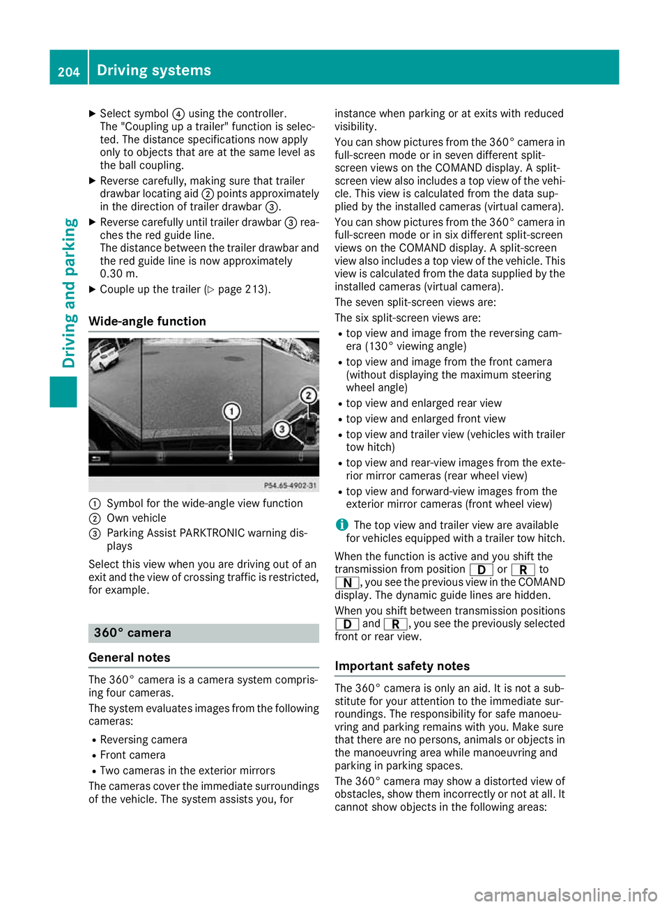
Wide-angle function :
Symbol for the wide-angle view function
; Own vehicle
= Parking Assist PARKTRONIC warning dis-
plays
Select this view when you are driving out of an
exit and the view of crossing traffic is restricted, for example. 360° camera
General notes The 360° camera is a camera system compris-
ing four cameras.
The system evaluates images from the following
cameras:
R Reversing camera
R Front camera
R Two cameras in the exterior mirrors
The cameras cover the immediate surroundings
of the vehicle. The system assists you, for instance when parking or at exits with reduced
visibility.
You can show pictures from the 360° camera in
full-screen mode or in seven different split-
screen views on the COMAND display. A split-
screen view also includes a top view of the vehi-
cle. This view is calculated from the data sup-
plied by the installed cameras (virtual camera).
You can show pictures from the 360° camera in
full-screen mode or in six different split-screen
views on the COMAND display. A split-screen
view also includes a top view of the vehicle. This
view is calculated from the data supplied by the installed cameras (virtual camera).
The seven split-screen views are:
The six split-screen views are:
R top view and image from the reversing cam-
era (130° viewing angle)
R top view and image from the front camera
(without displaying the maximum steering
wheel angle)
R top view and enlarged rear view
R top view and enlarged front view
R top view and trailer view (vehicles with trailer
tow hitch)
R top view and rear-view images from the exte-
rior mirror cameras (rear wheel view)
R top view and forward-view images from the
exterior mirror cameras (front wheel view)
i The top view and trailer view are available
for vehicles equipped with a trailer tow hitch.
When the function is active and you shift the
transmission from position 7orC to
A, you see the previous view in the COMAND
display. The dynamic guide lines are hidden.
When you shift between transmission positions 7 andC, you see the previously selected
front or rear view.
Important safety notes The 360° camera is only an aid. It is not a sub-
stitute for your attention to the immediate sur-
roundings. The responsibility for safe manoeu-
vring and parking remains with you. Make sure
that there are no persons, animals or objects in
the manoeuvring area while manoeuvring and
parking in parking spaces.
The 360° camera may show a distorted view of
obstacles, show them incorrectly or not at all. It
cannot show objects in the following areas: 204
Driving systemsDriving an
d parking
Page 208 of 369
R
under the front bumper
R very close to the front bumper
R very close to the rear bumper
R under the rear bumper
R in the area immediately above the recessed
handle on the boot lid
R very close to the exterior mirrors
You are responsible for safety at all times and
must always pay attention to your immediate
surroundings when parking and manoeuvring.
This applies to the areas behind, in front of and
beside the vehicle. You could otherwise endan-
ger yourself and others.
The 360° camera will not function or will func-
tion only to a limited extent:
R if the doors are open
R if the exterior mirrors are folded in
R if the tailgate is open
R in heavy rain, snow or fog
R at night or in very dark places
R if the cameras are exposed to very bright light
R if the area is lit by fluorescent lamps or LED
lighting (the display may flicker)
R if there is a sudden change in temperature,
e.g. when driving into a heated garage in win- ter
R if the camera lenses are dirty or covered
R if the vehicle components in which the cam-
eras are fitted are damaged: In this event,
have the camera position and setting checked at a qualified specialist workshop
Do not use the 360° camera under such cir-
cumstances. You could otherwise injure others
or damage objects when parking the vehicle.
Activation conditions The 360° camera image can be displayed if:
R your vehicle is equipped with a 360° camera
R COMAND Online is switched on; see the sep-
arate COMAND Online operating instructions
R the 360° camera 360° camera function is activated Activating the 360° camera using the
SYS button X
Press the Wbutton for longer than 2 sec-
onds; see the separate COMAND Online oper-
ating instructions.
The following appears depending on whether
gear hork is selected:
R full-screen view with image from the front
camera
R full-screen view with image from the revers-
ing camera
Activating the 360° camera using
COMAND Online X
Press the Wbutton, see the separate
COMAND Online operating Instructions.
X Select System System by turning cVdthe COMAND
controller and press Wto confirm.
X Select 360°
360°camera
camera and press Wto confirm.
The following appears depending on whether
gear hork is selected:
R a split screen with top view and the image
from the front camera or
R a split screen with top view and the image
from the rear view camera
For further information on the COMAND con-
troller; see the separate COMAND Online oper-
ating instructions.
Switching on the 360° camera using
reverse gear You can show images from the 360° camera
automatically by engaging reverse gear.
X Make sure that the key is in position 2in the
ignition lock.
X Make sure that the Activation by R gear Activation by R gear
setting is active in COMAND Online, see the
separate COMAND Online operating instruc-
tions.
X To show the 360° camera image: engage
reverse gear.
The area behind the vehicle is shown in the
COMAND display in split-screen mode:
R vehicle with guide lines
R top view of the vehicle Driving systems
205Driving and parking Z
Page 212 of 369
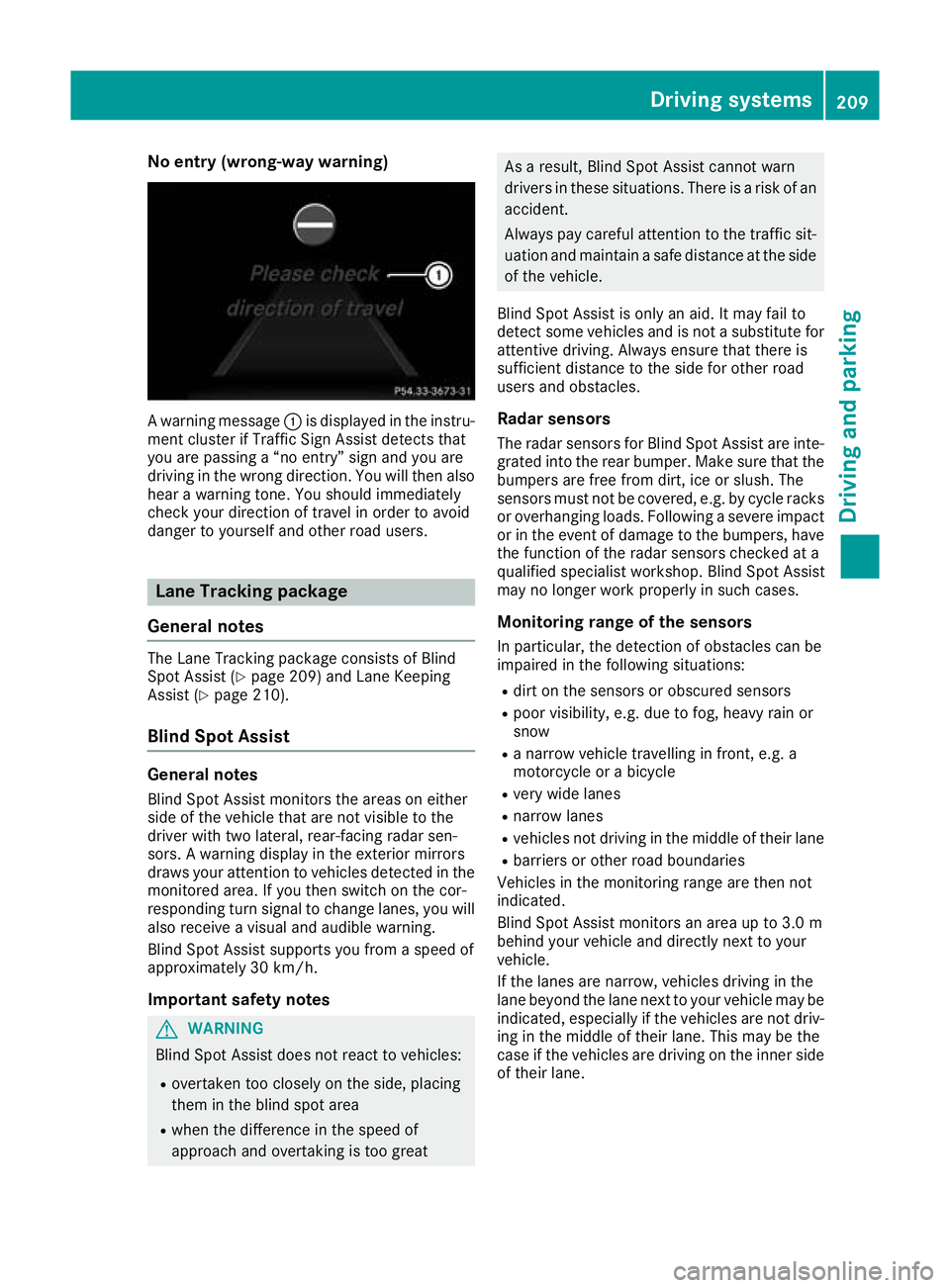
No entry (wrong-way warning)
A warning message
:is displayed in the instru-
ment cluster if Traffic Sign Assist detects that
you are passing a “no entry” sign and you are
driving in the wrong direction. You will then also hear a warning tone. You should immediately
check your direction of travel in order to avoid
danger to yourself and other road users. Lane Tracking package
General notes The Lane Tracking package consists of Blind
Spot Assist (Y
page 209) and Lane Keeping
Assist (Y page 210).
Blind Spot Assist General notes
Blind Spot Assist monitors the areas on either
side of the vehicle that are not visible to the
driver with two lateral, rear-facing radar sen-
sors. A warning display in the exterior mirrors
draws your attention to vehicles detected in the
monitored area. If you then switch on the cor-
responding turn signal to change lanes, you will also receive a visual and audible warning.
Blind Spot Assist supports you from a speed of
approximately 30 km/h.
Important safety notes G
WARNING
Blind Spot Assist does not react to vehicles:
R overtaken too closely on the side, placing
them in the blind spot area
R when the difference in the speed of
approach and overtaking is too great As a result, Blind Spot Assist cannot warn
drivers in these situations. There is a risk of an
accident.
Always pay careful attention to the traffic sit- uation and maintain a safe distance at the side
of the vehicle.
Blind Spot Assist is only an aid. It may fail to
detect some vehicles and is not a substitute for attentive driving. Always ensure that there is
sufficient distance to the side for other road
users and obstacles.
Radar sensors The radar sensors for Blind Spot Assist are inte-
grated into the rear bumper. Make sure that the bumpers are free from dirt, ice or slush. The
sensors must not be covered, e.g. by cycle racks
or overhanging loads. Following a severe impact
or in the event of damage to the bumpers, have the function of the radar sensors checked at a
qualified specialist workshop. Blind Spot Assist
may no longer work properly in such cases.
Monitoring range of the sensors
In particular, the detection of obstacles can be
impaired in the following situations:
R dirt on the sensors or obscured sensors
R poor visibility, e.g. due to fog, heavy rain or
snow
R a narrow vehicle travelling in front, e.g. a
motorcycle or a bicycle
R very wide lanes
R narrow lanes
R vehicles not driving in the middle of their lane
R barriers or other road boundaries
Vehicles in the monitoring range are then not
indicated.
Blind Spot Assist monitors an area up to 3.0 m
behind your vehicle and directly next to your
vehicle.
If the lanes are narrow, vehicles driving in the
lane beyond the lane next to your vehicle may be
indicated, especially if the vehicles are not driv-
ing in the middle of their lane. This may be the
case if the vehicles are driving on the inner side of their lane. Driving systems
209Driving and parking Z
Page 213 of 369
Due to the nature of the system:
R warnings may be issued in error when driving
close to crash barriers or similar solid boun-
daries
R warnings may be interrupted when you are
driving alongside particularly long vehicles,
such as lorries, for a prolonged time
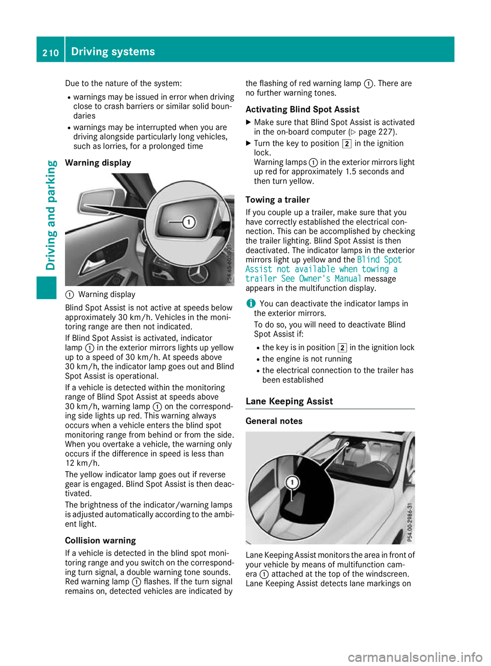
Warning display :
Warning display
Blind Spot Assist is not active at speeds below
approximately 30 km/h. Vehicles in the moni-
toring range are then not indicated.
If Blind Spot Assist is activated, indicator
lamp :in the exterior mirrors lights up yellow
up to a speed of 30 km/h. At speeds above
30 km/h, the indicator lamp goes out and Blind
Spot Assist is operational.
If a vehicle is detected within the monitoring
range of Blind Spot Assist at speeds above
30 km/h, warning lamp :on the correspond-
ing side lights up red. This warning always
occurs when a vehicle enters the blind spot
monitoring range from behind or from the side.
When you overtake a vehicle, the warning only
occurs if the difference in speed is less than
12 km/h.
The yellow indicator lamp goes out if reverse
gear is engaged. Blind Spot Assist is then deac- tivated.
The brightness of the indicator/warning lamps
is adjusted automatically according to the ambi-
ent light.
Collision warning
If a vehicle is detected in the blind spot moni-
toring range and you switch on the correspond-
ing turn signal, a double warning tone sounds.
Red warning lamp :flashes. If the turn signal
remains on, detected vehicles are indicated by the flashing of red warning lamp
:. There are
no further warning tones.
Activating Blind Spot Assist X Make sure that Blind Spot Assist is activated
in the on-board computer (Y page 227).
X Turn the key to position 2in the ignition
lock.
Warning lamps :in the exterior mirrors light
up red for approximately 1.5 second s and
then turn yellow.
Towing a trailer
If you couple up a trailer, make sure that you
have correctly established the electrical con-
nection. This can be accomplished by checking
the trailer lighting. Blind Spot Assist is then
deactivated. The indicator lamps in the exterior
mirrors light up yellow and the Blind Spot
Blind Spot
Assist not available when towing a Assist not available when towing a
trailer See Owner's Manual trailer See Owner's Manual message
appears in the multifunction display.
i You can deactivate the indicator lamps in
the exterior mirrors.
To do so, you will need to deactivate Blind
Spot Assist if:
R the key is in position 2in the ignition lock
R the engine is not running
R the electrical connection to the trailer has
been established
Lane Keeping Assist General notes
Lane Keeping Assist monitors the area in front of
your vehicle by means of multifunction cam-
era :attached at the top of the windscreen.
Lane Keeping Assist detects lane markings on 210
Driving systemsDriving an
d parking
Page 234 of 369
X
Press the :or9 button to set the
selected display.
X Press the abutton to store the entry.
The yellow indicator lamp on the auxiliary
heating button lights up.
Comfort Switching belt adjustment on/off
X Press the =or; button on the steering
wheel to select the Settings Settingsmenu.
X Press the :or9 button to select the
Convenience
Convenience submenu.
X Press ato confirm.
X Press the :or9 button to select the
Belt adjustment
Belt adjustment function.
When the Belt adjustment
Belt adjustment function is acti-
vated, the seat belt is displayed in orange in
the multifunction display.
X Press the abutton to save the setting.
Further information on belt adjustment
(Y page 45).
Switching the fold mirrors in when lock-
ing function on/off This function is only available when the vehicle is
equipped with the electrical fold-in function.
When you activate the Auto. fold-in mir‐
Auto. fold-in mir‐
rors
rors function, the exterior mirrors are folded in
when the vehicle is locked. When you unlock the vehicle and then open the driver's or front-
passenger door, the exterior mirrors fold out
again.
If you have switched on the Auto. fold-in
Auto. fold-in
mirrors
mirrors function and you fold in the exterior
mirrors using the button on the door
(Y page 113), they will not fold out automati-
cally. The exterior mirrors can then only be fol-
ded out using the button on the door.
X Press the =or; button on the steering
wheel to select the Settings
Settings menu.
X Press the :or9 button to select the
Convenience Convenience submenu.
X Press ato confirm.
X Press the :or9 button to select the
Auto. fold-in mirrors
Auto. fold-in mirrors function.
If the Auto. fold-in mirrors
Auto. fold-in mirrors function is
switched on, the multifunction display shows the exterior mirror in orange.
X Press ato save the setting. Resetting to factory settings X
Press the =or; button on the steering
wheel to select the Settings
Settingsmenu.
X Press the :or9 button to select the
Factory setting
Factory setting submenu.
X Press ato confirm.
The Reset all settings?
Reset all settings? function
appears.
X Press the :or9 button to select No
Noor
Yes
Yes.
X Press the abutton to confirm the selec-
tion.
If you have selected Yes Yes, the multifunction
display shows a confirmation message.
For safety reasons, not all functions are reset:
the Limit Limit speed
speed(winter
(winter tyres)
tyres)function of
the permanent speed limiter can only be set in
the Vehicle
Vehicle submenu.
If you want to reset the Daytime driving Daytime driving
lights
lights function in the Lights
Lightssubmenu, you
must turn the key to position 1in the ignition
lock. AMG menu (Mercedes-AMG vehicles)
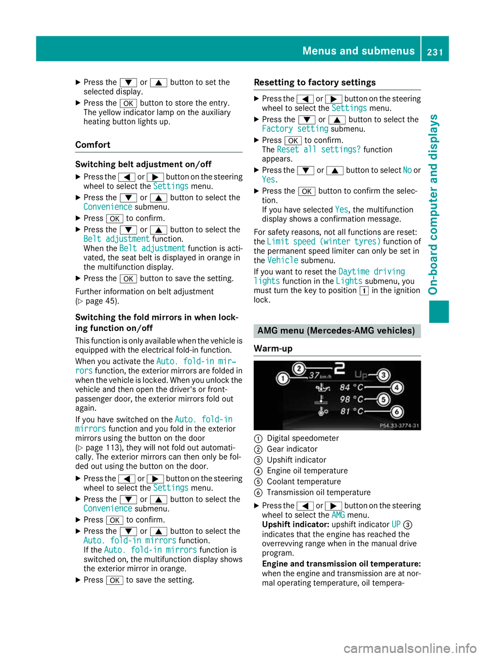
Warm-up :
Digital speedometer
; Gear indicator
= Upshift indicator
? Engine oil temperature
A Coolant temperature
B Transmission oil temperature
X Press the =or; button on the steering
wheel to select the AMG AMGmenu.
Upshift indicator: upshift indicatorUP UP=
indicates that the engine has reached the
overrevving range when in the manual drive
program.
Engine and transmission oil temperature: when the engine and transmission are at nor-
mal operating temperature, oil tempera- Menus and submenus
231On-board computer and displays Z
Page 250 of 369
Display messages
Possible causes/consequences and
M
MSolutions b
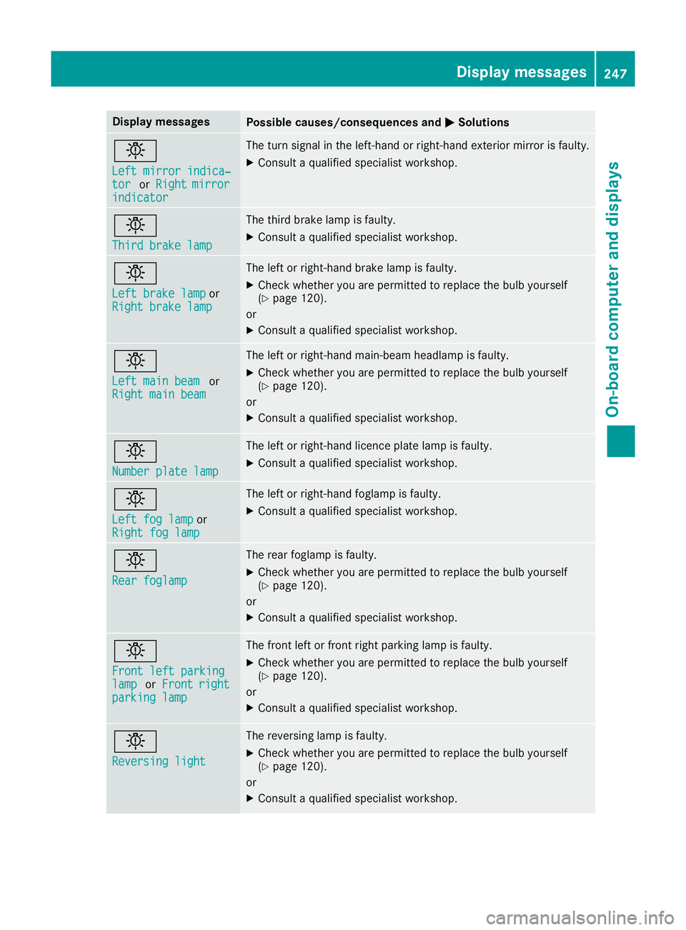
Left mirror indica‐ Left mirror indica‐
tor tor
orRight
Right mirror
mirror
indicator
indicator The turn signal in the left-hand or right-hand exterior mirror is faulty.
X Consult a qualified specialist workshop. b
Third brake lamp Third brake lamp The third brake lamp is faulty.
X Consult a qualified specialist workshop. b
Left brake lamp Left brake lamp
or
Right brake lamp
Right brake lamp The left or right-hand brake lamp is faulty.
X Check whether you are permitted to replace the bulb yourself
(Y page 120).
or
X Consult a qualified specialist workshop. b
Left main beam Left main beam
or
Right main beam
Right main beam The left or right-hand main-beam headlamp is faulty.
X Check whether you are permitted to replace the bulb yourself
(Y page 120).
or X Consult a qualified specialist workshop. b
Number plate lamp Number plate lamp The left or right-hand licence plate lamp is faulty.
X Consult a qualified specialist workshop. b
Left fog lamp Left fog lamp
or
Right fog lamp
Right fog lamp The left or right-hand foglamp is faulty.
X Consult a qualified specialist workshop. b
Rear foglamp Rear foglamp The rear foglamp is faulty.
X Check whether you are permitted to replace the bulb yourself
(Y page 120).
or X Consult a qualified specialist workshop. b
Front left parking Front left parking
lamp lamp
orFront
Front right
right
parking lamp
parking lamp The front left or front right parking lamp is faulty.
X Check whether you are permitted to replace the bulb yourself
(Y page 120).
or X Consult a qualified specialist workshop. b
Reversing light Reversing light The reversing lamp is faulty.
X Check whether you are permitted to replace the bulb yourself
(Y page 120).
or
X Consult a qualified specialist workshop. Display
messages
247On-board computer and displays Z
Page 256 of 369
Display messages
Possible causes/consequences and
M
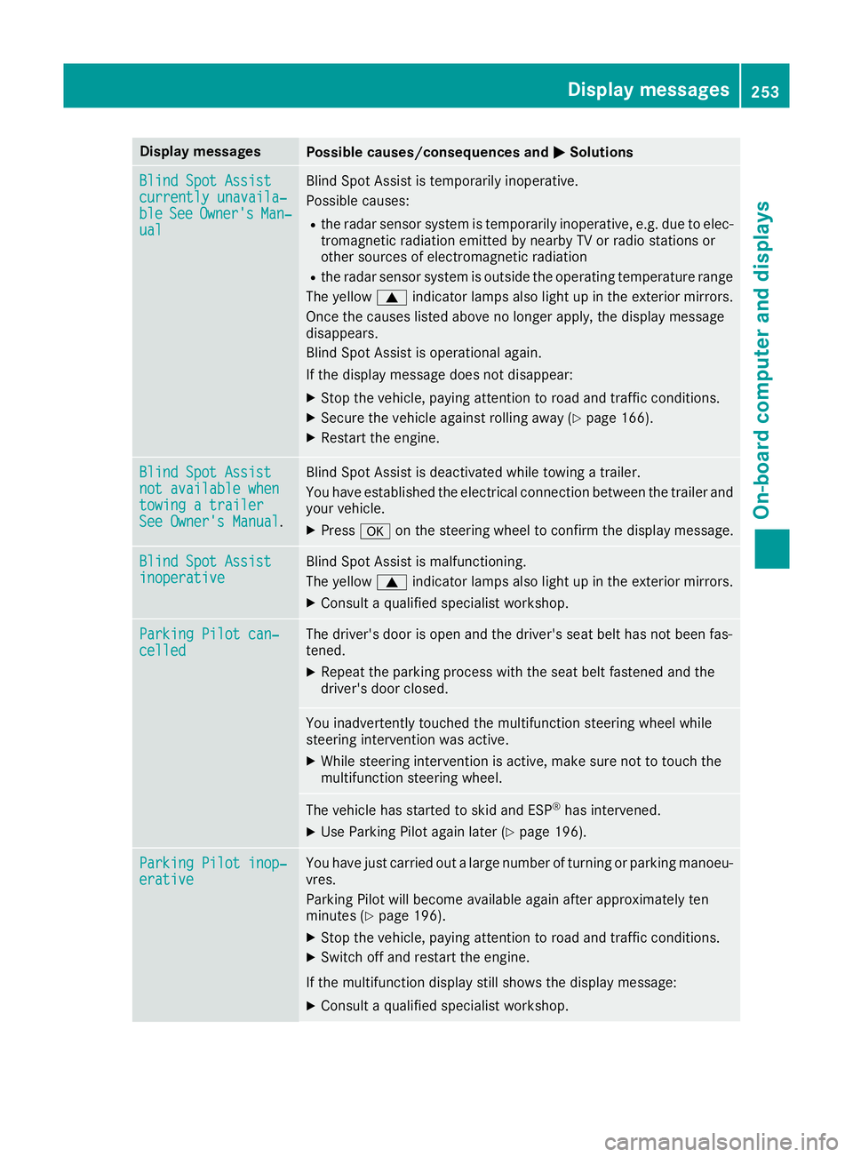
MSolutions Blind Spot Assist
Blind Spot Assist
currently unavaila‐ currently unavaila‐
ble ble
See
SeeOwner's
Owner's Man‐
Man‐
ual
ual Blind Spot Assist is temporarily inoperative.
Possible causes:
R the radar sensor system is temporarily inoperative, e.g. due to elec-
tromagnetic radiation emitted by nearby TV or radio stations or
other sources of electromagnetic radiation
R the radar sensor system is outside the operating temperature range
The yellow 9indicator lamps also light up in the exterior mirrors.
Once the causes listed above no longer apply, the display message
disappears.
Blind Spot Assist is operational again.
If the display message does not disappear:
X Stop the vehicle, paying attention to road and traffic conditions.
X Secure the vehicle against rolling away (Y page 166).
X Restart the engine. Blind Spot Assist Blind Spot Assist
not available when not available when
towing a trailer towing a trailer
See Owner's Manual See Owner's Manual
. Blind Spot Assist is deactivated while towing a trailer.
You have established the electrical connection between the trailer and
your vehicle.
X Press aon the steering wheel to confirm the display message. Blind Spot Assist
Blind Spot Assist
inoperative inoperative Blind Spot Assist is malfunctioning.
The yellow
9indicator lamps also light up in the exterior mirrors.
X Consult a qualified specialist workshop. Parking Pilot can‐ Parking Pilot can‐
celled celled The driver's door is open and the driver's seat belt has not been fas-
tened.
X Repeat the parking process with the seat belt fastened and the
driver's door closed. You inadvertently touched the multifunction steering wheel while
steering intervention was active.
X While steering intervention is active, make sure not to touch the
multifunction steering wheel. The vehicle has started to skid and ESP
®
has intervened.
X Use Parking Pilot again later (Y page 196).Parking Pilot inop‐ Parking Pilot inop‐
erative erative You have just carried out a large number of turning or parking manoeu-
vres.
Parking Pilot will become available again after approximately ten
minutes (Y page 196).
X Stop the vehicle, paying attention to road and traffic conditions.
X Switch off and restart the engine.
If the multifunction display still shows the display message:
X Consult a qualified specialist workshop. Display
messages
253On-board computer and displays Z
Page 300 of 369
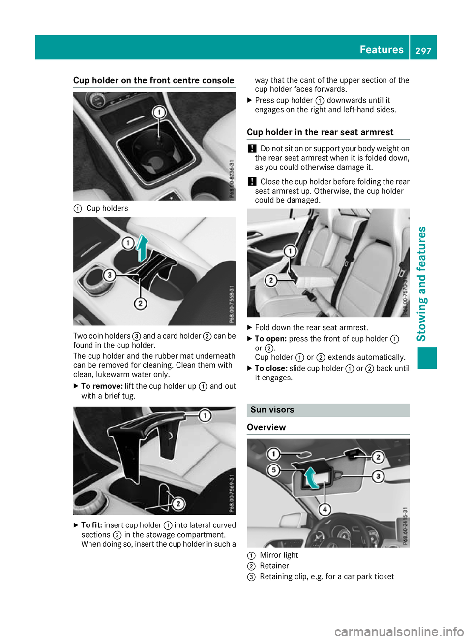
Cup holder on the front centre console
:
Cup holders Two coin holders
=and a card holder ;can be
found in the cup holder.
The cup holder and the rubber mat underneath
can be removed for cleaning. Clean them with
clean, lukewarm water only.
X To remove: lift the cup holder up :and out
with a brief tug. X
To fit: insert cup holder :into lateral curved
sections ;in the stowage compartment.
When doing so, insert the cup holder in such a way that the cant of the upper section of the
cup holder faces forwards.
X Press cup holder :downwards until it
engages on the right and left-hand sides.
Cup holder in the rear seat armrest !
Do not sit on or support your body weight on
the rear seat armrest when it is folded down,
as you could otherwise damage it.
! Close the cup holder before folding the rear
seat armrest up. Otherwise, the cup holder
could be damaged. X
Fold down the rear seat armrest.
X To open: press the front of cup holder :
or ;.
Cup holder :or; extends automatically.
X To close: slide cup holder :or; back until
it engages. Sun visors
Overview :
Mirror light
; Retainer
= Retaining clip, e.g. for a car park ticket Features
297Stowing and features Z