2017 MERCEDES-BENZ GLA SUV battery location
[x] Cancel search: battery locationPage 16 of 369

H
Handling control system see ESP ®
(Electronic Stability Program)
HANDS-FREE ACCESS ................... 91, 95
Hazard warning lamps
Display message ............................ 263
Switching on/off ........................... 118
Head restraints
Adjusting ....................................... 108
Adjusting (manually) ...................... 109
Adjusting (rear) .............................. 109
Fitting/removing (rear) .................. 109
Headlamp flasher .............................. 118
Headlamps
Misting up ...................................... 119
see Automatic headlamp mode
Heating
see Climate control
High-pressure cleaners .................... 309
Hill start assist .................................. 147
HOLD function
Activating ....................................... 187
Activation conditions .................... .186
Deactivating ................................... 187
Display message ............................ 252
Function/notes ............................ .186
Home address
See also Digital Owner's Manual ... 277
Horn ...................................................... 32 I
Ignition key see Key
Ignition lock
see Key positions
Immobiliser .......................................... 76
Indicator and warning lamp
Restraint system ............................ 272
Indicator and warning lamps
Coolant .......................................... 273
Engine diagnostics ......................... 272
SPORT handling mode ................... 270
Indicator lamps
Display message ............................ 246
see Warning and indicator lamps Indicators
see Turn signals
Instrument cluster
Overview .......................................... 34
Settings ......................................... 228
Warning and indicator lamps ........... 34
Instrument cluster lighting .............. 217
Interior lighting
Control .......................................... .120
Overview ........................................ 119
Reading lamp ................................. 119
Interior motion sensor
Deactivating ..................................... 78
Function .......................................... .77
Priming ............................................ 77
Switching off .................................... 77
iPod ®
See also Digital Owner's Manual ... 277
ISOFIX child seat securing system ....57 J
Jack Declaration of conformity ................27
Storage location ............................ 317
Using ............................................. 344
Jump starting (engine) ...................... 325 K
Key Changing the battery ....................... 82
Checking the battery ....................... 82
Convenience closing feature ............ 99
Convenience opening feature .......... 98
Display message ............................ 263
Door central locking/unlocking ....... 79
Emergency key element ................... 81
Important safety notes .................... 79
Loss ................................................. 84
Modifying the programming ............. 81
Positions (ignition lock) ................. 144
Problem (malfunction) ..................... 84
Starting the engine ........................ 146
Key positions
Start/Stop button .......................... 144
Key positions (ignition lock) ............ 144 Index
13
Page 143 of 369

time and at an unsuitable location. When setting
the departure time, observe the important
safety notes (Y page 137).
X Briefly press the ubutton.
X Press the ,or. button repeatedly
until the time to be changed appears in the
display.
X Press the uand^ buttons at the same
time.
The Îsymbol in the remote control display
flashes.
X Press the ,or. button to set the
desired departure time.
i The longer you press the
,or. but-
ton, the faster the time changes.
X Press the uand^ buttons at the same
time.
The new departure time is stored.
Activating the set departure time X Briefly press the ubutton.
X Press the ,or. button repeatedly
until the desired departure time appears in
the display.
X Press the ubutton.
The Ísymbol, the departure time and,
depending on the selected departure time,
the letter A, BorCappear in the display.
Deactivating the set departure time
X Briefly press the ubutton.
The status of the auxiliary heating is shown on
the display.
X Press the .button.
The first departure time stored appears on the
display.
X Press the ^button.
OFF is shown in the remote control display.
Replacing the remote control battery Important safety notes
G
WARNING
Batteries contain toxic and corrosive substan- ces. If batteries are swallowed, it can result in
severe health problems. There is a risk of fatal injury. Keep batteries out of the reach of children. If
a battery is swallowed, seek medical attention
immediately. H
Environmental note Batteries contain pollutants.
It is illegal to dispose of them
with the household rubbish.
They must be collected sep-
arately and disposed of in anenvironmentally responsible
recycling system. Dispose of batteries in an
environmentally responsible
manner. Take discharged
batteries to a qualified spe-
cialist workshop or to a col-
lection point for used batter-
ies.
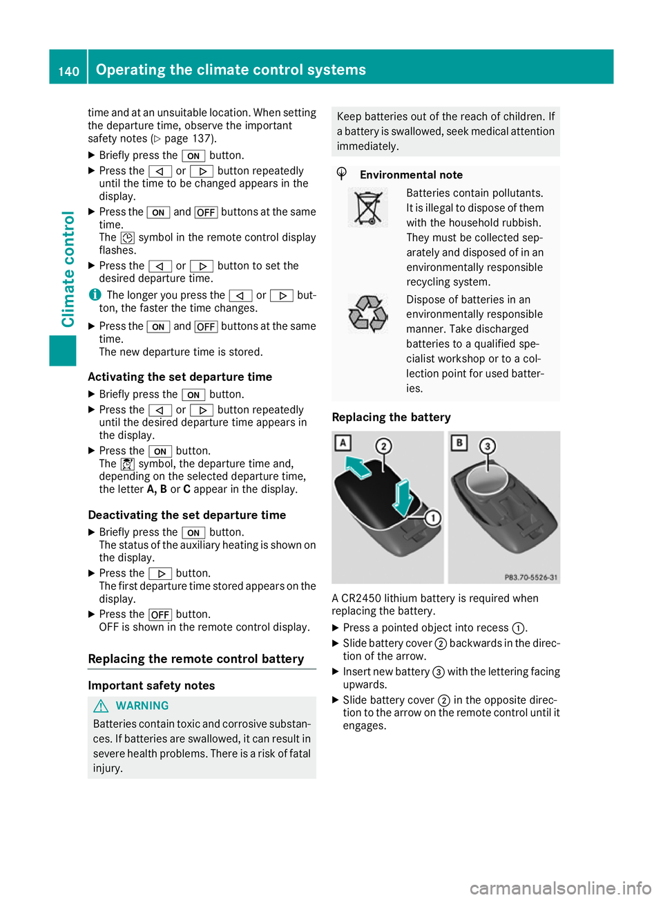
Replacing the battery A CR2450 lithium battery is required when
replacing the battery.
X Press a pointed object into recess :.
X Slide battery cover ;backwards in the direc-
tion of the arrow.
X Insert new battery =with the lettering facing
upwards.
X Slide battery cover ;in the opposite direc-
tion to the arrow on the remote control until it engages. 140
Operating the climate control systemsClimate control
Page 334 of 369

Vehicles with 4MATIC may only be either towed
away with both axles on the ground or be loadedup and transported.
If the vehicle has transmission damage or dam-
age to the front or rear axle, have it transported on a transporter or trailer.
In the event of damage to the electrical sys-
tem:
If the battery is defective, the automatic trans-
mission will be locked in position j. To shift the
automatic transmission to position i, you
must provide power to the vehicle's on-board
electrical system in the same way as when jump- starting (Y page 325).
Have the vehicle transported on a transporter or trailer. Tow-starting (emergency engine
starting)
! Do not tow-start vehicles with automatic
transmission. You could otherwise damage
the automatic transmission.
i You can find information on "Jump-starting"
under (Y page 325).
Before tow-starting, the following conditions
must be fulfilled: R the battery is connected
R the engine has cooled down
R the exhaust system has cooled down
When tow-starting, it is important that you
observe the safety notes (Y page 327) and the
legal requirements in each respective country.
X Switch on the hazard warning lamps
(Y page 118).
X Fit the towing eye (Y page 328).
X Secure the rigid towing bar or the towing
rope.
X When the vehicle is stationary, depress the
brake pedal and keep it depressed.
X Turn the key to position 2in the ignition lock
(Y page 144).
X Depress the clutch pedal fully, engage second
gear and continue to keep the clutch pedal
fully depressed.
X Release the brake pedal.
X Tow-start the vehicle.
X Release the clutch pedal slowly; do not
depress the accelerator pedal while doing so. X
When the engine has been started, immedi-
ately depress the clutch pedal fully and shift
to neutral.
X Pull over at a suitable place and stop the vehi-
cle safely, paying attention to road and traffic
conditions.
X Use the electric parking brake to secure the
vehicle and prevent it from rolling away.
X Remove the rigid towing bar or towing rope.
X Remove the towing eye (Y page 329).
X Switch off the hazard warning lamps. Fuses
Important safety notes
G
WARNING
If you manipulate, bridge or replace a faulty
fuse with a fuse of a higher amperage, the
electric cables could be overloaded. This may result in a fire. There is a risk of an accident
and injury.
Always replace faulty fuses with specified newfuses of the correct amperage.
! Only use fuses that have been approved for
Mercedes-Benz vehicles and which have the
correct fuse rating for the system concerned.
Only use fuses marked with an "S". Compo-
nents or systems could otherwise be dam-
aged.
! Make sure that no moisture can enter the
fuse box when the cover is open.
! When closing the cover, make sure that it is
lying correctly on the fuse box. Moisture seep-
ing in or dirt could otherwise impair the oper- ation of the fuses.
The fuses in your vehicle disconnect faulty cir-
cuits. If a fuse blows, all the components in the circuit and their functions will fail.
Blown fuses must be replaced with fuses of the same rating, which you can recognise by the
colour and fuse rating. The fuse ratings are listed
in the fuse allocation chart.
The fuse allocation chart is in the fuse box in the front-passenger footwell (Y page 332).
If the newly inserted fuse also blows, have the
cause traced and rectified at a qualified special- Fuses
331Breakdown assistance Z