2017 MERCEDES-BENZ GLA SUV light
[x] Cancel search: lightPage 199 of 369
Parking Pilot
General notes Parking Pilot is an electronic parking aid with
ultrasound. It measures the road on both sides
of the vehicle. A parking symbol indicates a suit-
able parking space. Active steering intervention
and brake application can assist you during
parking and when exiting a parking space. Park- ing Assist PARKTRONIC is also available
(Y page 193).
i The active braking application is only avail-
able on vehicles with automatic transmission.
Important safety notes Parking Pilot is only an aid. It is not a substitute
for your attention to the immediate surround-
ings. The responsibility for safe manoeuvring
and parking remains with you. Make sure that no
persons, animals or objects are in the manoeu-
vring range.
When Parking Assist PARKTRONIC is deactiva-
ted, Parking Pilot is also unavailable. G
WARNING
While parking or pulling out of a parking
space, the vehicle swings out and can drive
onto areas of the oncoming lane. This could
cause you to collide with other road users.
There is a risk of an accident.
Pay attention to other road users. Stop the
vehicle if necessary or cancel the Parking Pilot parking procedure.
! If unavoidable, you should drive over obsta-
cles such as kerbs slowly and not at a sharp
angle. Otherwise, you may damage the
wheels or tyres.
Parking Pilot may also display spaces not suita- ble for parking, e.g.:
R in a zone where parking or stopping is pro-
hibited
R in front of driveways or entrances and exits
R on unsuitable surfaces
Parking tips:
R on narrow roads, drive as closely as possible
past the parking space
R parking spaces that are littered or overgrown
might be identified or measured incorrectly R
parking spaces that are partially occupied by
trailer drawbars might not be identified as
such or be measured incorrectly
R snowfall or heavy rain may lead to a parking
space being measured inaccurately
R pay attention to the Parking Assist
PARKTRONIC warning messages
(Y page 194) during the parking procedure
R you can intervene in the steering procedure to
correct it at any time. Parking Pilot will then be cancelled
R when transporting a load that protrudes from
your vehicle, you should not use Parking Pilot
R never use Parking Pilot when snow chains are
fitted
R make sure that the tyre pressures are always
correct. This has a direct influence on the
parking characteristics of the vehicle
Use Parking Pilot for parking spaces that are:
R parallel or at right angles to the direction of
travel
R on straight roads, not bends
R on the same level as the road, e.g. not on the
pavement
For vehicles with the trailer tow hitch folded out,
the minimum length for parking spaces is
slightly longer.
If you have attached a trailer to your vehicle, you
should not use Parking Pilot. Once the electrical connection is established between your vehicle
and the trailer, Parking Pilot is no longer availa-
ble. Parking Assist PARKTRONIC is deactivated
for the rear area.
Detecting parking spaces Objects located above the detection range of
Parking Pilot will not be detected when the park-
ing space is measured. These are not taken into
account when the parking procedure is calcula- ted, e.g. overhanging loads, tail sections or load-
ing ramps of goods vehicles. Parking Pilot may
therefore guide you into the parking space too
early.
Parking Pilot does not assist you parking in
spaces at right angles to the direction of travel if:
R two parking spaces are located directly next
to one another
R the parking space is directly next to a low
obstacle such as a low kerb
R you forward-park 196
Driving systemsDriving and parking
Page 203 of 369
Cancelling Parking Pilot
X
Stop the movement of the multifunction
steering wheel or steer yourself.
Parking Pilot is cancelled at once. The Park‐ Park‐
ing Pilot cancelled
ing Pilot cancelled message appears in
the multifunction display.
or X Press the PARKTRONIC button (Y page 195).
Parking Assist PARKTRONIC is switched off
and Parking Pilot is immediately cancelled.
The Parking Pilot cancelled
Parking Pilot cancelled message
appears in the multifunction display.
Parking Pilot is cancelled automatically when:
R the electric parking brake is applied
R transmission position jis selected in vehi-
cles with automatic transmission
R parking using Parking Pilot is no longer pos-
sible
R you are driving at a speed greater than
10 km/h
R a wheel spins and ESP ®
intervenes or fails. In
such cases the ÷warning lamp lights up
on the instrument cluster
A warning tone sounds. The parking symbol dis-
appears and the multifunction display shows the
Parking Pilot cancelled
Parking Pilot cancelled message.
When Parking Pilot is cancelled, you must steer and brake again yourself.
If a system malfunction occurs, the vehicle is
braked to a standstill. To drive on, depress the
accelerator pedal again. Rear view camera
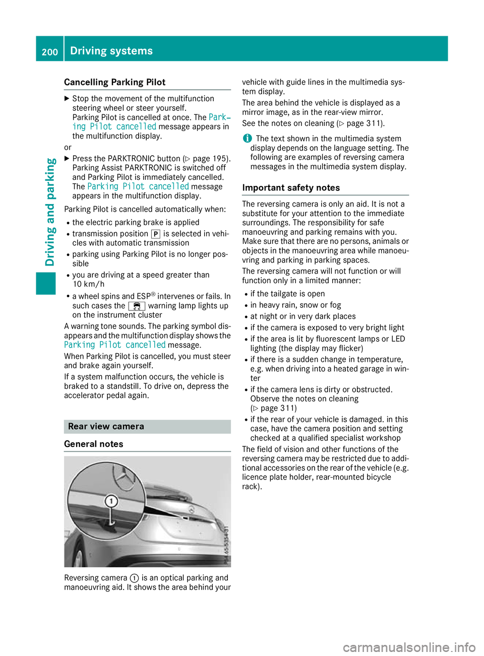
General notes Reversing camera
:is an optical parking and
manoeuvring aid. It shows the area behind your vehicle with guide lines in the multimedia sys-
tem display.
The area behind the vehicle is displayed as a
mirror image, as in the rear-view mirror.
See the notes on cleaning (Y
page 311).
i The text shown in the multimedia system
display depends on the language setting. The following are examples of reversing camera
messages in the multimedia system display.
Important safety notes The reversing camera is only an aid. It is not a
substitute for your attention to the immediate
surroundings. The responsibility for safe
manoeuvring and parking remains with you.
Make sure that there are no persons, animals or
objects in the manoeuvring area while manoeu-
vring and parking in parking spaces.
The reversing camera will not function or will
function only in a limited manner:
R if the tailgate is open
R in heavy rain, snow or fog
R at night or in very dark places
R if the camera is exposed to very bright light
R if the area is lit by fluorescent lamps or LED
lighting (the display may flicker)
R if there is a sudden change in temperature,
e.g. when driving into a heated garage in win-
ter
R if the camera lens is dirty or obstructed.
Observe the notes on cleaning
(Y page 311)
R if the rear of your vehicle is damaged. in this
case, have the camera position and setting
checked at a qualified specialist workshop
The field of vision and other functions of the
reversing camera may be restricted due to addi-
tional accessories on the rear of the vehicle (e.g. licence plate holder, rear-mounted bicycle
rack). 200
Driving systemsDriving and parking
Page 204 of 369
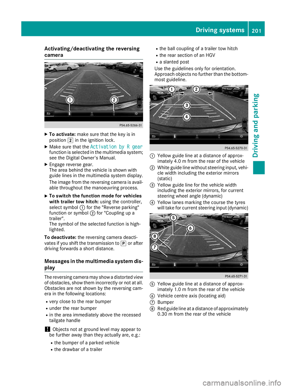
Activating/deactivating the reversing
camera X
To activate: make sure that the key is in
position 2in the ignition lock.
X Make sure that the Activation by R gear
Activation by R gear
function is selected in the multimedia system; see the Digital Owner's Manual.
X Engage reverse gear.
The area behind the vehicle is shown with
guide lines in the multimedia system display.
The image from the reversing camera is avail-
able throughout the manoeuvring process.
X To switch the function mode for vehicles
with trailer tow hitch: using the controller,
select symbol :for the "Reverse parking"
function or symbol ;for "Coupling up a
trailer".
The symbol of the selected function is high-
lighted.
To deactivate: the reversing camera deacti-
vates if you shift the transmission to jor after
driving forwards a short distance.
Messages in the multimedia system dis-
play The reversing camera may show a distorted view
of obstacles, show them incorrectly or not at all. Obstacles are not shown by the reversing cam-
era in the following locations:
R very close to the rear bumper
R under the rear bumper
R in the area immediately above the recessed
tailgate handle
! Objects not at ground level may appear to
be further away than they actually are, e.g.:
R the bumper of a parked vehicle
R the drawbar of a trailer R
the ball coupling of a trailer tow hitch
R the rear section of an HGV
R a slanted post
Use the guidelines only for orientation.
Approach objects no further than the bottom-
most guideline. :
Yellow guide line at a distance of approx-
imately 4.0 m from the rear of the vehicle
; White guide line without steering input, vehi-
cle width including the exterior mirrors
(static)
= Yellow guide line for the vehicle width
including the exterior mirrors, for current
steering wheel angle (dynamic)
? Yellow lanes marking the course the tyres
will take for current steering input (dynamic) A
Yellow guide line at a distance of approx-
imately 1.0 m from the rear of the vehicle
B Vehicle centre axis (locating aid)
C Bumper
D Red guide line at a distance of approximately
0.30 m from the rear of the vehicle Driving systems
201Driving and parking Z
Page 205 of 369
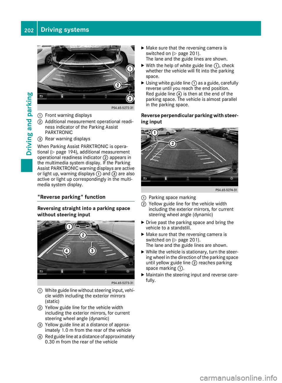
:
Front warning displays
; Additional measurement operational readi-
ness indicator of the Parking Assist
PARKTRONIC
= Rear warning displays
When Parking Assist PARKTRONIC is opera-
tional (Y page 194), additional measurement
operational readiness indicator ;appears in
the multimedia system display. If the Parking
Assist PARKTRONIC warning displays are active
or light up, warning displays :and =are also
active or light up correspondingly in the multi-
media system display.
"Reverse parking" function Reversing straight into a parking space
without steering input :
White guide line without steering input, vehi-
cle width including the exterior mirrors
(static)
; Yellow guide line for the vehicle width
including the exterior mirrors, for current
steering wheel angle (dynamic)
= Yellow guide line at a distance of approx-
imately 1.0 m fromthe rear of the vehicle
? Red guide line at a distance of approximately
0.30 m from the rear of the vehicle X
Make sure that the reversing camera is
switched on (Y page 201).
The lane and the guide lines are shown.
X With the help of white guide line :, check
whether the vehicle will fit into the parking
space.
X Using white guide line :as a guide, carefully
reverse until you reach the end position.
Red guide line ?is then at the end of the
parking space. The vehicle is almost parallel
in the parking space.
Reverse perpendicular parking with steer- ing input :
Parking space marking
; Yellow guide line for the vehicle width
including the exterior mirrors, for current
steering wheel angle (dynamic)
X Drive past the parking space and bring the
vehicle to a standstill.
X Make sure that the reversing camera is
switched on (Y page 201).
The lane and the guide lines are shown.
X While the vehicle is stationary, turn the steer-
ing wheel in the direction of the parking spaceuntil yellow guide line ;reaches parking
space marking :.
X Maintain the steering input and reverse care-
fully. 202
Driving systemsDriving an
d parking
Page 206 of 369
:
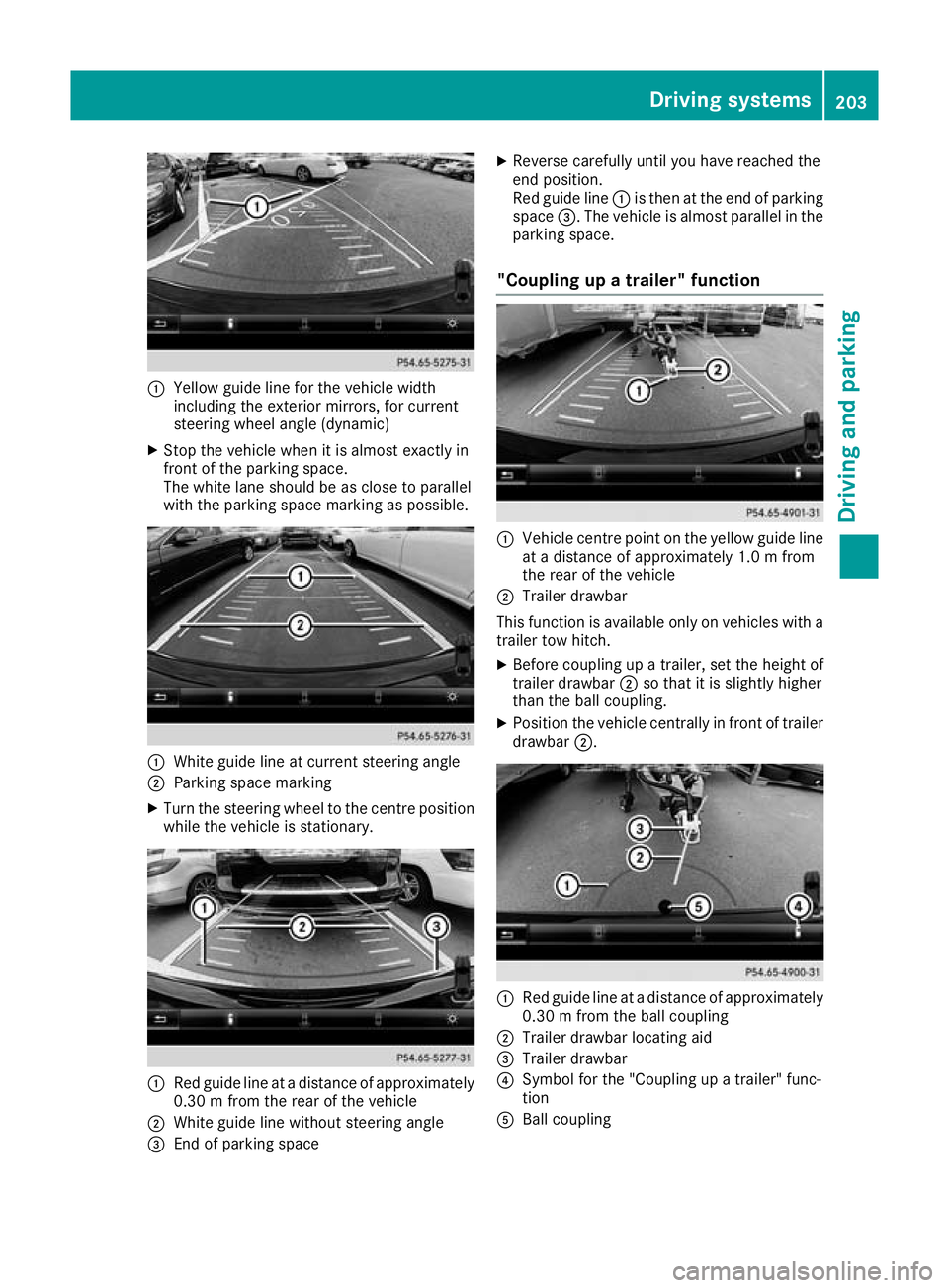
Yellow guide line for the vehicle width
including the exterior mirrors, for current
steering wheel angle (dynamic)
X Stop the vehicle when it is almost exactly in
front of the parking space.
The white lane should be as close to parallel
with the parking space marking as possible. :
White guide line at current steering angle
; Parking space marking
X Turn the steering wheel to the centre position
while the vehicle is stationary. :
Red guide line at a distance of approximately
0.30 m from the rear of the vehicle
; White guide line without steering angle
= End of parking space X
Reverse carefully until you have reached the
end position.
Red guide line :is then at the end of parking
space =. The vehicle is almost parallel in the
parking space.
"Coupling up a trailer" function :
Vehicle centre point on the yellow guide line
at a distance of approximately 1.0 m from
the rear of the vehicle
; Trailer drawbar
This function is available only on vehicles with a
trailer tow hitch.
X Before coupling up a trailer, set the height of
trailer drawbar ;so that it is slightly higher
than the ball coupling.
X Position the vehicle centrally in front of trailer
drawbar ;. :
Red guide line at a distance of approximately
0.30 m from the ball coupling
; Trailer drawbar locating aid
= Trailer drawbar
? Symbol for the "Coupling up a trailer" func-
tion
A Ball coupling Driving systems
203Driving and parking Z
Page 208 of 369
R
under the front bumper
R very close to the front bumper
R very close to the rear bumper
R under the rear bumper
R in the area immediately above the recessed
handle on the boot lid
R very close to the exterior mirrors
You are responsible for safety at all times and
must always pay attention to your immediate
surroundings when parking and manoeuvring.
This applies to the areas behind, in front of and
beside the vehicle. You could otherwise endan-
ger yourself and others.
The 360° camera will not function or will func-
tion only to a limited extent:
R if the doors are open
R if the exterior mirrors are folded in
R if the tailgate is open
R in heavy rain, snow or fog
R at night or in very dark places
R if the cameras are exposed to very bright light
R if the area is lit by fluorescent lamps or LED
lighting (the display may flicker)
R if there is a sudden change in temperature,
e.g. when driving into a heated garage in win- ter
R if the camera lenses are dirty or covered
R if the vehicle components in which the cam-
eras are fitted are damaged: In this event,
have the camera position and setting checked at a qualified specialist workshop
Do not use the 360° camera under such cir-
cumstances. You could otherwise injure others
or damage objects when parking the vehicle.
Activation conditions The 360° camera image can be displayed if:
R your vehicle is equipped with a 360° camera
R COMAND Online is switched on; see the sep-
arate COMAND Online operating instructions
R the 360° camera 360° camera function is activated Activating the 360° camera using the
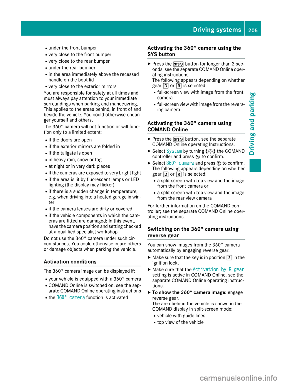
SYS button X
Press the Wbutton for longer than 2 sec-
onds; see the separate COMAND Online oper-
ating instructions.
The following appears depending on whether
gear hork is selected:
R full-screen view with image from the front
camera
R full-screen view with image from the revers-
ing camera
Activating the 360° camera using
COMAND Online X
Press the Wbutton, see the separate
COMAND Online operating Instructions.
X Select System System by turning cVdthe COMAND
controller and press Wto confirm.
X Select 360°
360°camera
camera and press Wto confirm.
The following appears depending on whether
gear hork is selected:
R a split screen with top view and the image
from the front camera or
R a split screen with top view and the image
from the rear view camera
For further information on the COMAND con-
troller; see the separate COMAND Online oper-
ating instructions.
Switching on the 360° camera using
reverse gear You can show images from the 360° camera
automatically by engaging reverse gear.
X Make sure that the key is in position 2in the
ignition lock.
X Make sure that the Activation by R gear Activation by R gear
setting is active in COMAND Online, see the
separate COMAND Online operating instruc-
tions.
X To show the 360° camera image: engage
reverse gear.
The area behind the vehicle is shown in the
COMAND display in split-screen mode:
R vehicle with guide lines
R top view of the vehicle Driving systems
205Driving and parking Z
Page 213 of 369
Due to the nature of the system:
R warnings may be issued in error when driving
close to crash barriers or similar solid boun-
daries
R warnings may be interrupted when you are
driving alongside particularly long vehicles,
such as lorries, for a prolonged time
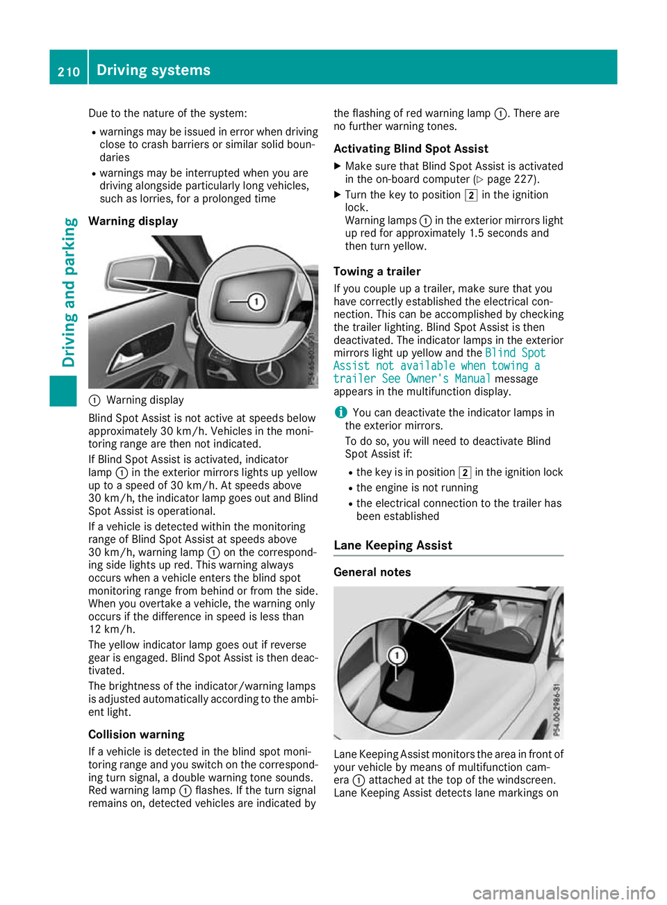
Warning display :
Warning display
Blind Spot Assist is not active at speeds below
approximately 30 km/h. Vehicles in the moni-
toring range are then not indicated.
If Blind Spot Assist is activated, indicator
lamp :in the exterior mirrors lights up yellow
up to a speed of 30 km/h. At speeds above
30 km/h, the indicator lamp goes out and Blind
Spot Assist is operational.
If a vehicle is detected within the monitoring
range of Blind Spot Assist at speeds above
30 km/h, warning lamp :on the correspond-
ing side lights up red. This warning always
occurs when a vehicle enters the blind spot
monitoring range from behind or from the side.
When you overtake a vehicle, the warning only
occurs if the difference in speed is less than
12 km/h.
The yellow indicator lamp goes out if reverse
gear is engaged. Blind Spot Assist is then deac- tivated.
The brightness of the indicator/warning lamps
is adjusted automatically according to the ambi-
ent light.
Collision warning
If a vehicle is detected in the blind spot moni-
toring range and you switch on the correspond-
ing turn signal, a double warning tone sounds.
Red warning lamp :flashes. If the turn signal
remains on, detected vehicles are indicated by the flashing of red warning lamp
:. There are
no further warning tones.
Activating Blind Spot Assist X Make sure that Blind Spot Assist is activated
in the on-board computer (Y page 227).
X Turn the key to position 2in the ignition
lock.
Warning lamps :in the exterior mirrors light
up red for approximately 1.5 second s and
then turn yellow.
Towing a trailer
If you couple up a trailer, make sure that you
have correctly established the electrical con-
nection. This can be accomplished by checking
the trailer lighting. Blind Spot Assist is then
deactivated. The indicator lamps in the exterior
mirrors light up yellow and the Blind Spot
Blind Spot
Assist not available when towing a Assist not available when towing a
trailer See Owner's Manual trailer See Owner's Manual message
appears in the multifunction display.
i You can deactivate the indicator lamps in
the exterior mirrors.
To do so, you will need to deactivate Blind
Spot Assist if:
R the key is in position 2in the ignition lock
R the engine is not running
R the electrical connection to the trailer has
been established
Lane Keeping Assist General notes
Lane Keeping Assist monitors the area in front of
your vehicle by means of multifunction cam-
era :attached at the top of the windscreen.
Lane Keeping Assist detects lane markings on 210
Driving systemsDriving an
d parking
Page 218 of 369
The multifunction display shows the
Check
Check
trailer hitch lock
trailer hitch lock display message until
the ball coupling is engaged.
X Remove the protective cap from the ball cou-
pling and store it in a safe place.
X Make sure that the ball of the ball coupling is
clean and that it is either greased or dry
(grease free), depending on the instructions
for the trailer.
Folding in the ball coupling G
WARNING
If you release the ball coupling or it does not
engage correctly when folding in, it will swing out. Within pivoting range of the ball coupling,
there is an increased risk of an accident and
injury.
Only release the ball coupling if the pivoting
range is unobstructed. Always make sure that the ball coupling engages when folding in.
i Fold the ball coupling in if you are not using
the trailer tow hitch.
X Make sure that the vehicle is stationary and
the trailer cables are disconnected.
X Place the protective cap on the ball coupling.
i The release wheel is located behind the left-
hand side trim panel in the luggage compart- ment.
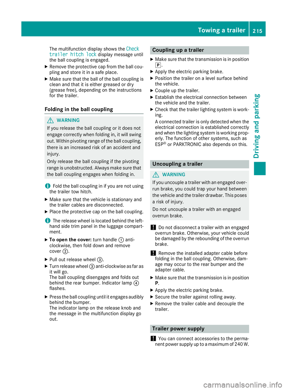
X To open the cover: turn handle:anti-
clockwise, then fold down and remove
cover ;.
X Pull out release wheel =.
X Turn release wheel =anti-clockwise as far as
it will go.
The ball coupling disengages and folds out
behind the rear bumper. Indicator lamp ?
flashes.
X Press the ball coupling until it engages audibly
behind the bumper.
The indicator lamp on the release knob and
the message in the multifunction display go
out. Coupling up a trailer
X Make sure that the transmission is in position
j.
X Apply the electric parking brake.
X Position the trailer on a level surface behind
the vehicle.
X Couple up the trailer.
X Establish the electrical connection between
the vehicle and the trailer.
X Check that the trailer lighting system is work-
ing.
A connected trailer is only detected when the
electrical connection is established correctly
and when the lighting system is working prop- erly. The function of other systems, such as
ESP ®
or PARKTRONIC also depends on this. Uncoupling a trailer
G
WARNING
If you uncouple a trailer with an engaged over- run brake, you could trap your hand between
the vehicle and the trailer drawbar. This poses a risk of injury.
Do not uncouple a trailer with an engaged
overrun brake.
! Do not disconnect a trailer with an engaged
overrun brake. Otherwise, your vehicle could
be damaged by the rebounding of the overrun brake.
! Remove the installed adapter cable before
folding in the ball coupling. Otherwise, dam-
age may occur to the rear bumper and the
adapter cable.
X Make sure that the transmission is in position
P.
X Apply the electric parking brake.
X Secure the trailer against rolling away.
X Remove the trailer cable and decouple the
trailer. Trailer power supply
! You can connect accessories to the perma-
nent power supply up to a maximum of 240 W. Towing a trailer
215Driving and parking Z