Page 145 of 286

Rear viewcamera
General notes
Rear vie wcamera :is an optical parking and
maneuvering aid. It shows the are abehind the
vehicl ewithg uide lines in the multimedi asys-
tem.
The are abehind the vehicl eisdisplayed as a
mirror image, as in the rearv iewm irror.
iThe text shown in the multimedi asystem
depends on the languag esetting. The follow-
ing are examples of rearv iewc amera displays
in the multimedi asystem.
Important safety notes
The rearv iewc amera is only an aid. It is not a
replacement for your attention to your immedi-
ate surroundings. Yo uare always responsible
for safe maneuvering and parking .Makes ure
that there are no persons,a nimalsoro bjects in
the maneuvering are awhile maneuvering and
parking in parking spaces.
Unde rthe following circumstances, the rear
vie wc amera will not function, or will function in
al im ite dm anner:
Rthe reard ooriso pen
Rin heavy rain, snow or fog
Rat nigh torinv ery dark places
Rif the camera is exposed to very bright light
Rif the are aislitby fluorescent bulb sorLED
lighting (the display may flicker)
Rif there is asudde nchange in temperature,
e.g. when driving into aheated garag einwin-
ter
Rif the camera lens is dirty or obstructed
Observe the notes on cleaning
(
Ypage 235)
Rif the rearofy ourv ehicl eisd amaged. In this
case, have the camera position and setting
checke dataq ualified specialist workshop
Activating/deactivatin gthe rear view
camera
XTo activate: make sure that the SmartKey is
in position 2in the ignition lock.
XMake sure that the "Rearv iewc amera" func-
tion is selected in the multimedi asystem (see
Digital Operator's Manual).
XEngag ereverse gear.
The multimedi asystem shows the area
behind the vehicl ewithg uide lines. Sym-
bol :indicates that the "reversep arking"
function is active.
The image from the rearv iewc amera is avail-
able throughout the maneuvering process.
XTo switc hthe functio nmode for vehicles
with trailer tow hitch: using the controller,
select symbol ;for "Coupling up atrailer".
Symbol ;is highlighted.
To deactivate: the rearviewc amera deacti-
vate sify oushift the transmissio ntoP or after
driving forward sashort distance.
Displays in the multimedias ystem
The rearviewc amera may showad istortedv iew
of obstacles, showt hem incorrectlyornot at all.
The rearv iewc amera doe snot showo bjects in
the following positions:
Rvery close to the rearb umper
Runder the rearb umper
Driving systems143
Driving and parking
Z
Page 146 of 286

!Objects that are not at ground level appear
further awayt han they actually are, e.g.:
Rthe bumper of aparked vehicle
Rthe drawbarofat railer
Rthe rear end ofatruck
Rap ost sticking up at an angle
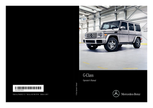
Use the guide lines for orientation only. Do
not cross the lower guide line when approach-
ing objects.
:Yellowg uide line at adistance of approx-
imately 13 ft (4.0 m) from the rear of the
vehicle
;White guide line without steering input –
vehicle width including the exterior mirrors
(static)
=Yellowg uide line for the vehicle width
including the exterior mirrors, for current
steering wheel angle (dynamic)
?Yellowl anes marking the course the tires
will take for current steering input (dynamic)
AYellowg uide line at adistance of approx-
imately 3ft(1.0 m) from the rear of the vehi-
cle
BVehicle center axle (marker assistance)
CSpare wheel
DRed guide line at adistance of approximately
12 in (0.30 m)from the rear of the vehicle
The guide lines are shownw hen the transmis-
sion is in position R. The distance specifications only apply to
objects that are at ground level.
:Front warning display
;Additional vehiclei
con: PARKTRONIC meas-
urement operational readiness indicator
=Rea rwarning display
Vehicles with PARKTRONIC: when PARKTRONIC
is operational (
Ypag e140), additiona lmeas-
urement operational readiness indicator ;
appears in the multimedias ystem. If the
PARKTRONIC warning display sare active or
light up, warning displays :and =are also
active or light up correspondinglyint he multi-
medias ystem.
"Coupling up atrailer" function
:Trailer drawbar
This function is only available on vehicles with a
trailer tow hitch.
XBefore coupling up atrailer, set the height of
trailer drawbar :so that it is slightly higher
than the bal lcoupling.
XPosition the vehiclec entrallyinfront of trailer
drawbar :.
144Driving systems
Driving and parking
Page 147 of 286
f romt he ball coupling
;Trailer drawbar marker assistant
=Trailer drawbar
?Symbo lfor the \"Coupling up atrailer\" func-
tion
iThe trailer tow hit")
:Red guide lineatadistanceofapproximately
12 in (0.30m)f romt he ball coupling
;Trailer drawbar marker assistant
=Trailer drawbar
?Symbo lfor the "Coupling up atrailer" func-
tion
iThe trailer tow hitch is not visible in the mul-
timedia systemd isplay,asthe spar ewheel
covers the ball coupling of the trailer tow
hitch.
XSelect symbol ?using the controller.
The "Coupling up atrailer" functio niss elec-
ted .The distance specifications now only
appl ytoo bjects thata reat the same level as
the ball coupling.
XReverse carefully, making sure thatt railer
drawbar locating aid ;points approximately
in the direction of trailer drawbar =.
XReverse carefullyuntiltrailer drawbar =rea-
che sred guid eline:. Do no tdriv ea ny fur-
ther.
The distance between trailer drawbar =and
red guid eline : is now approximately 12 in
(0.3 0m).
XCoupl eupthe trailer (Ypage 151).
180° view
:Symbo lfor the 180° vie wfunction
;Ownv ehicle
=PARKTRONICw arning displays
Yo uc an also us ethe rea rviewc amera to select
a1 80° view.
When PARKTRONICi soperational (
Ypage 140),
as ym bolfor your ow nvehicl eappears in the
multimedia system. If the PARKTRONICw arning
displays ar eactive, warning displays =light up
in the multimedia systeminy elloworr ed
accordingly.
Off-roa ddrivin gsystems
Transferc ase
General notes
The vehicl ehaspermanent all-wheel drive. The
front and rea raxles ar econstantl ydriven.
For furtheri nformation on drivin goff-road, see
(
Ypage 127).
Shift ranges
HIGH
RANGEPositio nfor al lnormal on-
roa ddrivin gconditions
LOWR ANGELow-range positio nfor driving
off-road.
Als ofor us eons teep uphill or
downhil lgradients ,especially
when towing atrailer.
The vehicl etravel saround
half the spee dofon-road driv-
ing range HIGH RANGE .The
tractiv epower is correspond-
ingly higher.
Off-roa ddrivin gsystems145
Driving an dparking
Z
Page 148 of 286

Shifting the transfer case
General notes
:Current shift range
:Indicator lamp
;LOW RANGE button
Important safety notes
GWARNING
If you do not wait for the transfer case gear
change process to complete, the transfer
case could remain in the neutral position. The power transmission to the driven wheels is
then interrupted. There is adanger of the
vehicle rolling away unintentionally. There is a
risk of an accident.
Wait until the transfer case shift process is
completed.
Do not switch off the engine while changing gear
and do not shift the automatic transmission to
another gear.
Always wait for the gear change process from
HIGH RANGE toLOW RANGE and fromLOW
RANGE toHIGH RANGE to complete. Do not
switch off the engine while changing gear and do
not shift the automatic transmission to another
gear.
Switching on the off-road gear ratio
!Proceed with the shifting process only
when:
Rthe engine is running
Rthe vehicle is rolling
Rthe automatic transmission is in selector
lever position i
Ryou are not driving faster than 25 mph
(40 km/h)
You could otherwise damage the transfer
case.
XMake sure the ECO start/stop function is
switched off (Ypage 106).
XPress LOW RANGE button ;.
Once the shifting procedure has been com-
pleted, the LOW RANGE
transfer case position
is shown in the multifunction display.
Indicator lamp :lights up.
XShift the automatic transmission to position
D.
Switching off the off-road gear ratio
GWARNING
If you do not wait for the transfer case gear
change process to complete, the transfer
case could remain in the neutral position. The power transmission to the driven wheels is
then interrupted. There is adanger of the
vehicle rolling away unintentionally. There is a
risk of an accident.
Wait until the transfer case shift process is
completed.
!Proceed with the shifting process only
when:
Rthe engine is running
Rthe vehicle is rolling
Rthe automatic transmission is in selector
lever position i
Ryou are not driving faster than 43 mph
(70 km/h)
You could otherwise damage the transfer
case.
XPress button ;.
Once the shifting procedure has been com-
pleted, the HIGH
RANGEtransfer case position
is shown in the multifunction display.
Indicator lamp :goes out.
146Off-road driving systems
Driving and parking
Page 149 of 286

If the shifting procedure is unsuccessful, the
multifunction display may show the following
messages:
RTC Shift Conditions Not Fulfilled
You have not met one or more shift condi-
tions.
RTC NEUTRAL On
The transfer case has canceled the shifting
procedure and is in positionN.
RTC Shift Canceled
The transfer case has canceled the gear
change process.
XCarry out the gear change process again.
Make sure to meet all conditions for changing
gears.
RTC Malfunction Visit Workshop
There is amalfunction in the transfer case.
XDo not shift the transfer case.
XHave the vehicle checked as soon as possible
ataq ualifieds pecialist workshop.
Shifting to neutral
GWARNING
If you do not wai tfor the transfer case gear
change process to complete, the transfer
case could remain in the neutral position. The powert ransmission to the driven wheelsi s
then interrupted. There is adanger of the
vehicle rolling awa yunintentionally .There is a
risk of an accident.
Waitu ntil the transfer case shift process is
completed.
XTurn the SmartKey to position 2in the ignition
lock.
XApply the parking brake.
XDepress the brake pedal.
XShift the automatic transmission to position
N.
XPress and hold LOW RANGE button ;for
approximately ten seconds.
When the shift procedure is complete, the
multifunction display shows the TC
NEUTRALOnmessagefor five seconds.
If the shifting procedure is unsuccessful, the
multifunction display may show the following
messages (
Ypage 179). If the transfer case is in
Neutral,the SmartKey
is in the ignition lock and you open the driver's
door, the TC NEUTRAL On
messagea ppears in
the multifunction display. If you then release the
parking brake, awarning tone wills ound.
Differential locks
General notes
GWARNING
When the differentiall ocks are engaged,ABS,
4ETS, ESP
®and BAS are deactivated. As a
result, the wheelsc ould lock when braking
and the braking distance is increased.T here is
ar isk of an accident.
Disengage the differentiall ocks immediately
on firm surfaces with good grip.
!In order to avoid damage to the transfer
case, you must operate the vehicle on adyna-
mometer (1-axle dynamometer) only if:
Rthe axle not driven on is jacked up
or
Rthe corresponding propeller shaft is dis-
connected and the transfer case differen-
tial lock is engaged.
Otherwise,t he transfer case can be damaged.
Differential locks improve the traction of the
vehicle.
Your vehicle is equipped with adifferentiall ock
each for:
Rthe transfer case: this controls the balance
betweent he front and rear axles.
Rthe rear axle: this controls the balance
betweenthe wheelsont he rear axle.
Rthe front axle: this controls the balance
betweenthe wheelsont he front axle.
Information on differential gear system
and differential lock
When the vehicle drives around acurve, the
wheelsont he outsideoft he curve must cover a
greater distance. Therefore, the wheelst urn
more rapidly than on the inside. The differential,
ag ear system in the drive train, allows for dif-
fering rotational speedsa nd facilitates corner-
ing.
Off-road driving systems147
Driving and parking
Z
Page 150 of 286

The disadvantage ofadifferential is that the
wheels that have the least grip, get the most
drive. An example: awheel of adriven axle is on
as now-covered surface and therefor edoes not
have any traction. The differential sends most of
the drive force to this wheel because the force
takes the route of the lowest resistance. The
opposite wheel on this axle, however, which
stands on firm ground and could therefor eallow
propulsion, receives no driving power. 4ETS
compensates for this disadvantage. 4ETS pro-
vides good steerability by automatically braking
the spinnin gwheel. 4ETS provides the wheel on
the firm surface with more drive force, which in
turn provides propulsion.
ESP
®and 4ETS are traction systems that are
ideal for road driving and suitable for light off-
road driving. The LOW RANGEoff-road gear
also improves off-road capability.
More challenging off-road conditions require
additional measures such as lockingo ne or
more differential.
Your vehicle is equipped with three differential
locks:
Rfor the transfer case
Rfor the front axle
Rfor the rear axle
Each differential lock can be engaged with the
corresponding switch on the center console. If
the differential in the transfer case is locked, the
front and rear wheels rotateatt he same speed.
If the differential for the rear axle is locked, both
rear wheels rotateatt he same speed, regard-
less of their respective torque. Note, engaging
the differential lock greatly impairs the vehicle's
steerability.
Note, it is imperative to use the differential func-
tion when driving on firm road surfaces. Under
no circumstances should the differential be
locked when driving on firm road surfaces. Oth-
erwise, the vehicle may not be steerable and you
could lose control of the vehicle. Therefore, only
engage the differential lock when driving off-
road. You should only engage the differential
lock if activatin g4ETS and ESP
®driving systems
and LOW RANGE off-road gear prove to be
insufficient.
Engaging the differential locks
General notes
The switches are located on the center console.
:Function indicator lamps (red)
;Differential lock for the front axle
=Differential lock for the transfer case
?Differential lock for the rear axle
AActivation indicator lamps (yellow)
Engage the differential locks:
Roff-road
Rto deactivate ABS,4 ETS,ESP®and BAS while
off-road
Rwhen fording
For further information on driving off-road, see
(
Ypage 127).
You can engage the differential locks in the fol-
lowing order: =,?,;.
Important safety notes
GWARNING
When differential locks are engaged on afirm,
high-grip surface, the vehicle's steerability is
greatly impaired. In particular, engaging the
differential locks when cornering could lead
to you losing control of the vehicle. There is a risk of an accident.
Disengage the differential locks immediately
on firm surfaces with good grip.
GWARNING
When the differential locks are engaged, ABS, 4ETS ,ESP
®and BAS are deactivated. As a
result, the wheels could lock when braking
and the braking distance is increased. There is
ar isk of an accident.
148Off-road driving systems
Driving and parking
Page 151 of 286

Disengagethe differential locks immediately
on fir msurfaces with good grip.
!Onlye ngagethe differential locks when:
Ryoua redrivin gatw alking pace
Rthe drive wheels ar enot spinning
Ryoua renot drivin gonafirmr oads urface
Differential lock fort he transfercase
XTo engage: switch the transferc asetot he
LO WR ANGE off-roaddrivin gposit ion
(
Ypage 146).
XPress switch =.
If the transferc aseisint heLOWR ANGE off-
roa dposit ion, the yellow activatio nindicator
lamp under switch =lights up.
The å warning lamp in the instrument
cluster lights up.
If the differential is locked ,the red function
indicator lamp above switch =lights up.
In the multifunctio ndisplay yous ee the:
ABS Not Available Differential
Locks Activemessage.
The å!÷ warning lamps light up in
the instrument cluster.
The differential lock for the transferc asei s
engaged.
4ETS, ESP
®,B AS and ABS ar edeactivated.
The vehicle's ability to stee risseverely restric-
ted .Drivec arefull yand accelerate gently for
optimu mtraction.
Yo uc an now engag ethe differential lock for rear
axle ?and the differential lock for front axle ;
as required.
Differential lock fort he rear axle
XTo engage:press switch ?.
Yellow activatio nindicator lamp Alights up
first, followe dbyred functio nindicator
lamp :of switch ?.
The differential lock for the rea raxlei s
engaged.
Differential lock fort he front axle
XTo engage:press switch ;.
First, the yellow activatio nindicator lamp
lights up ,followe dbythe red functio nindica-
tor lamp. The differential lock for the front axl
eis
engaged.
Disengaging the differential locks
Yo uc an disengage the differential locks in the
following order: ;,?,=.
XTo simultaneously disengag eall differen-
tial locks: press switch =.
Yellow activatio nindicator lamps Aand red
functio nindicator lamps :go out.
After approximately threes econdsofnormal
driving, ABS, 4ETS, ESP
®and BAS ar eactiva-
ted.
The ABS Not Available Differential
Locks Activemessage disappears in the
multifunctio ndisplay and the å,!and
÷ warning lamps in the instrument cluster
go out.
XShift the transferc asetot heHIGH RANGE
on-road positio n(Ypage 146).
If red functio nindicator lamps :do not go out
when disengaging the differential locks, stop
the vehicl esafelyina ccordance with the traffic
conditions and thend rive on. The load change
can disengage the differential locks.
Towin gatrailer
Important safety notes
GWARNING
If yo uresty ou rfoo tont he brake peda lwhile
driving, the braking system can overheat. This increases the stopping distance and can even
cause the braking system to fail .There is a
ris kofana ccident.
Never us ethe brake peda lasafootrest. Never
depress the brake peda land the accelerator
peda latthe same time.
GWARNING
When the vehicle/trailer combinatio nbegin s
to lurch, yo ucould lose contro lofit. The vehi-
cle/trailer combinatio ncould eve nrollover.
There is ariskofana ccident.
On no account shoul dyou attempt to
straightenu pthe vehicle/trailer combination
Towin gatrailer149
Driving an dparking
Z
Page 152 of 286

by increasing the speed. Reduce vehicle
speed and do not countersteer. Apply the
brake as necessary.
GWARNING
If you install aball coupling other than the one
delivered with the vehicle, the trailer tow hitch
and the rear axle may be overloaded. This
applies especially if the ball coupling in ques-
tion is longer or angled differently. This could
seriously impair the driving characteristics
and the trailer can come loose. There is arisk
of an accident.
Only install the ball coupling delivered with
the vehicle or aball coupling that is designed
to meet your trailer towing requirements. Do
not modify the ball coupling or the trailer tow
hitch.
GWARNING
If the ball coupling is not installed correctly or not secured with the bolt provided and the
correspondin gspring cotter, the trailer may
come loose. There is arisk of an accident.
Always install and secure the ball coupling as
described. Beforee very journey, ensure that
the ball coupling is secured with the bolt and
the correspondin gspring cotter.
!If you have atrailer tow hitc hretrofitted,
changes to the engin ecooling system may be
necessary, dependin gonthe vehicle type.
If you have atrailer tow hitc hretrofitted,
observe the anchorage point sonthe chassis
frame.
The installation of atrailer tow hitc hisonly per-
missible if atowing weight is specified in your
vehicle documents. If this is not the case, then
the vehicle is not approved for the towing of a
trailer.
For more information ,please contact aqualified
specialist workshop.
Please observe the manufacturer's operating
instructions for the trailer coupling if adetach-
able trailer coupling is used.
Exceeding the maximum permissible nose-
weight of the trailer drawbar on the ball coupling may cause damage. Damage may be caused to the following:
RTowing vehicle
RTrailer
RBall coupling
RTrailer tow hitch
The vehicle/trailer combination could become
unstable.
If the noseweight used is lower than the mini-
mum permissible noseweight ,the vehicle/
trailer combination could also become unstable.
To avoid hazardous situations:
Rmake sure to checkt he noseweight before
each journey
Ruse adrawbar noseweight as close as possi-
ble to the maximum noseweight
Rdo not exceed the maximum permissible
noseweight
Rthe noseweight must not be lower than the
minimum permissible noseweight
Make sure that the following values are not
exceeded:
Rthe permissible trailer drawbar noseweight
Rthe permissible trailer load
Rthe permissible rear axle load of the towing
vehicle
Rthe maximum permissible gross vehicle
weight of both the towing vehicle and the
trailer
When backin gupthe vehicle towards the trailer,
make sure ther eisnobody between the trailer
and the vehicle.
The applicable permissible values, which must
not be ex
ceeded, can be found:
Rin your vehicle documents
Ron the type plate for the trailer
Ron the vehicle identification plate
If the values differ, the lowest value applies.
You will find the values approved by the manu-
facturer on the vehicle identification plates and
those for the towing vehicle under "Technical
data" (
Ypage 284).
When backin gupthe vehicle towards the trailer,
make sure ther eisnobody between the trailer
and the vehicle.
Couple and uncouple the trailer carefully. If you
do not couple the trailer to the towing vehicle
correctly, the trailer could become detached.
150Towing atrailer
Driving and parking
 1
1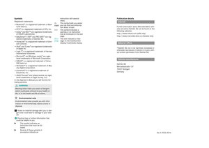 2
2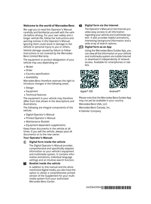 3
3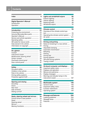 4
4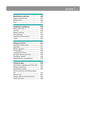 5
5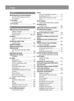 6
6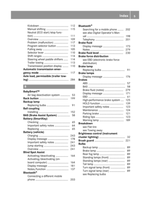 7
7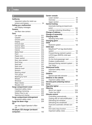 8
8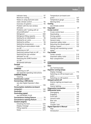 9
9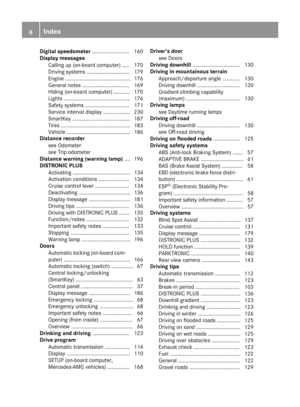 10
10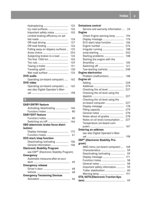 11
11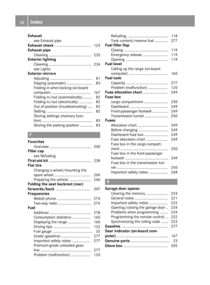 12
12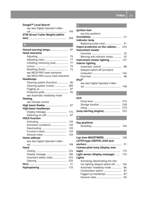 13
13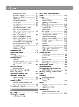 14
14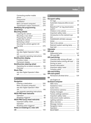 15
15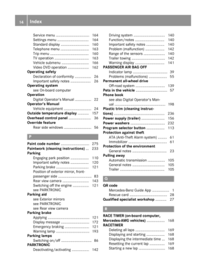 16
16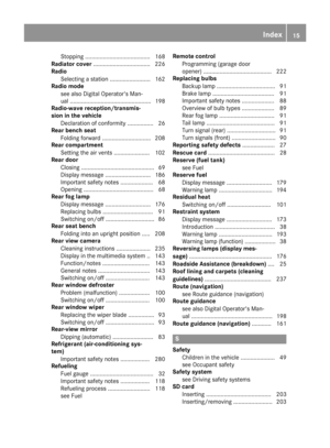 17
17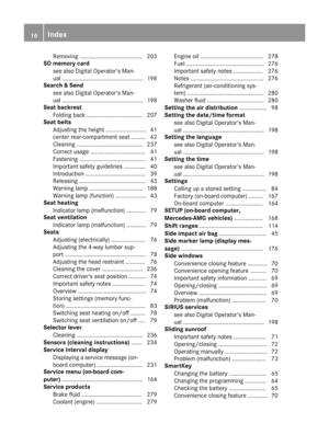 18
18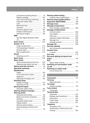 19
19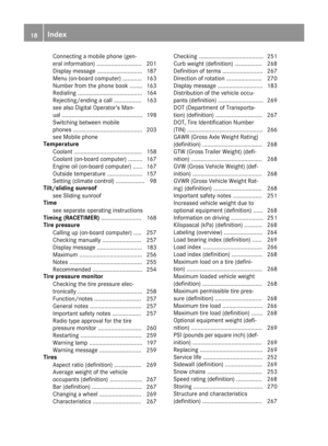 20
20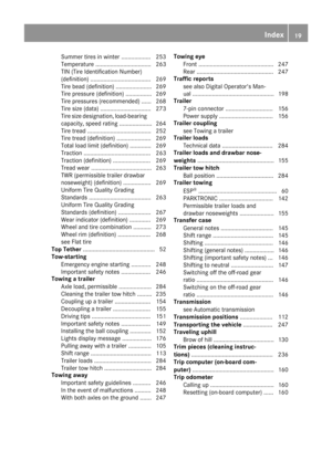 21
21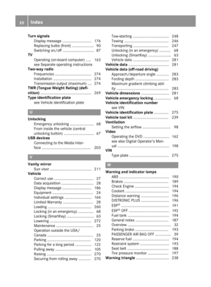 22
22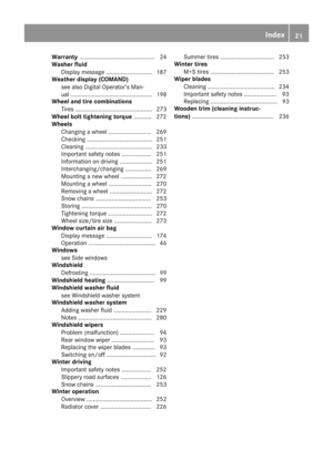 23
23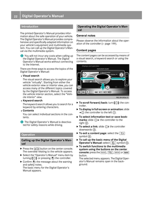 24
24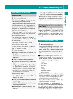 25
25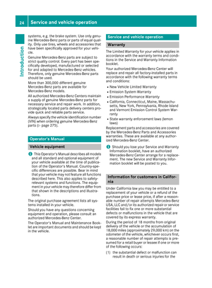 26
26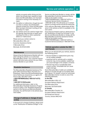 27
27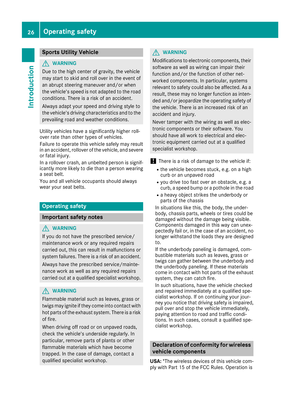 28
28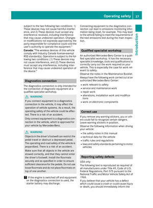 29
29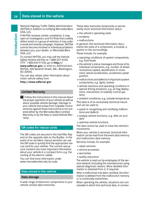 30
30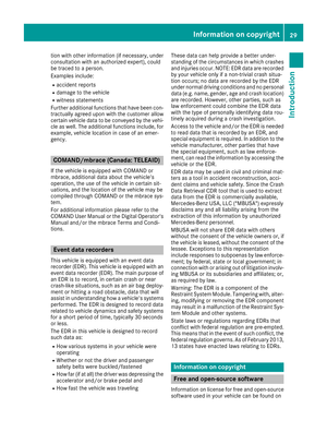 31
31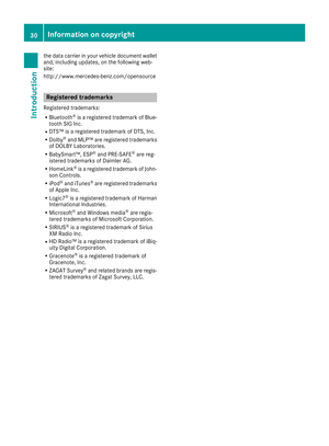 32
32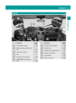 33
33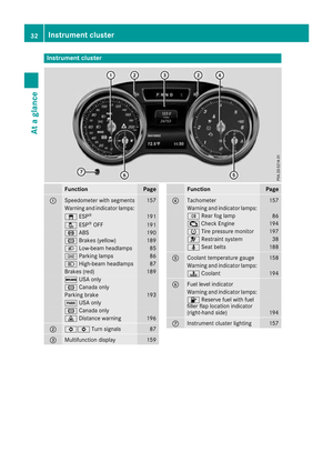 34
34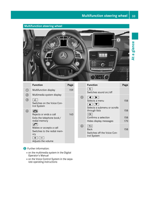 35
35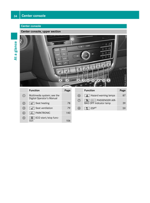 36
36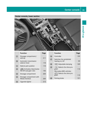 37
37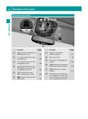 38
38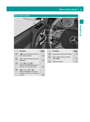 39
39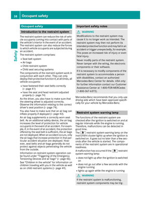 40
40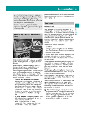 41
41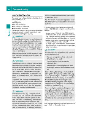 42
42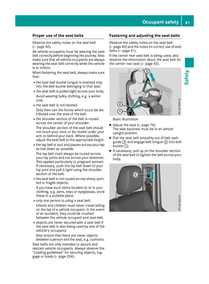 43
43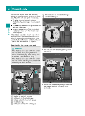 44
44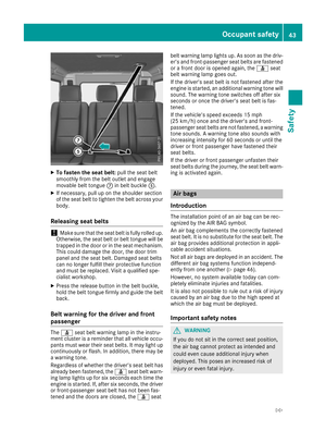 45
45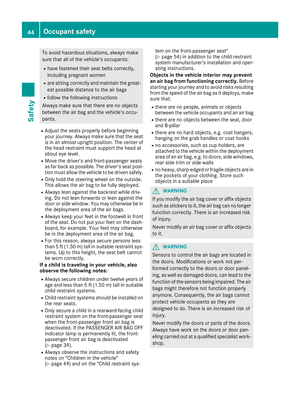 46
46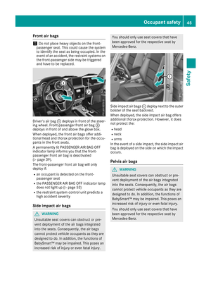 47
47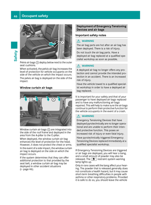 48
48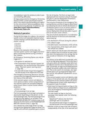 49
49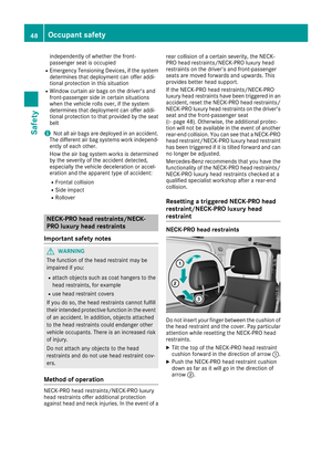 50
50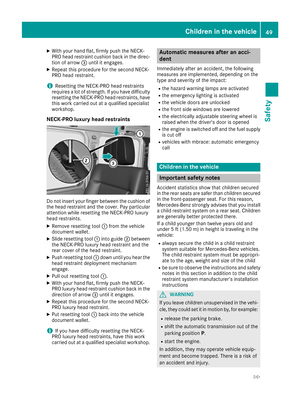 51
51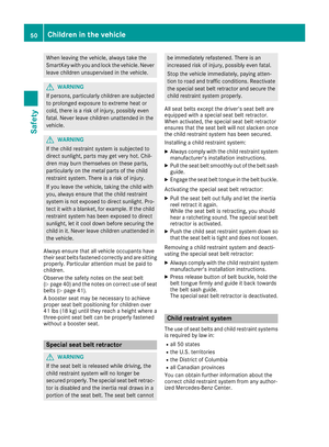 52
52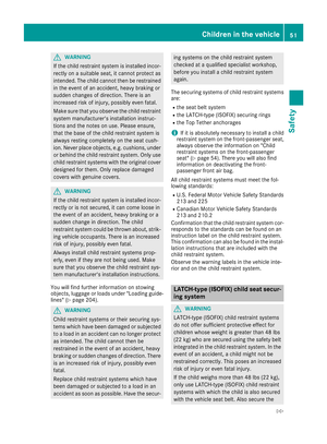 53
53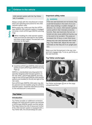 54
54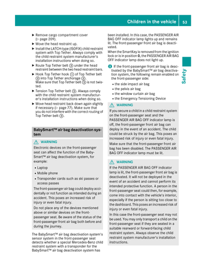 55
55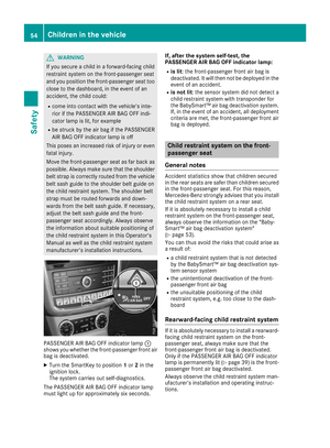 56
56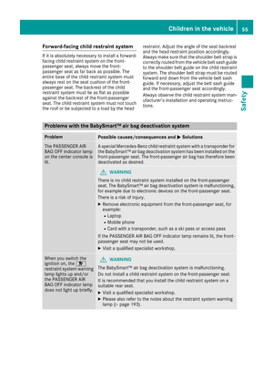 57
57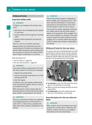 58
58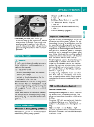 59
59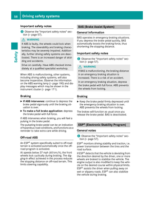 60
60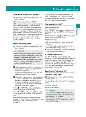 61
61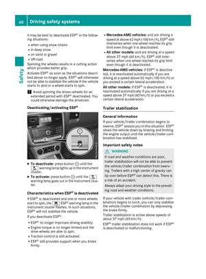 62
62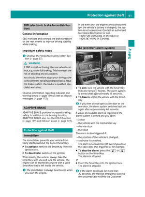 63
63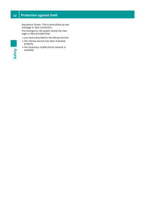 64
64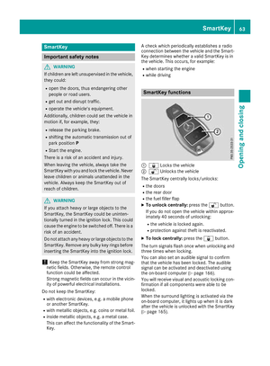 65
65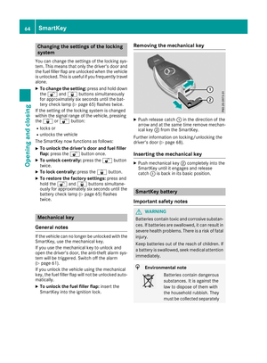 66
66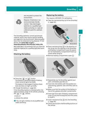 67
67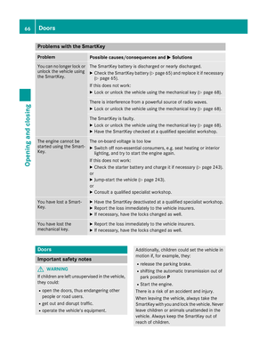 68
68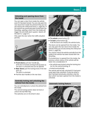 69
69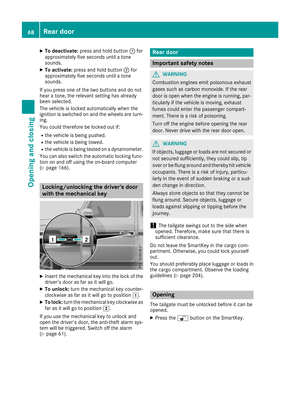 70
70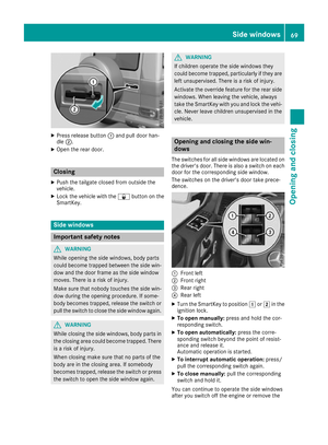 71
71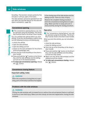 72
72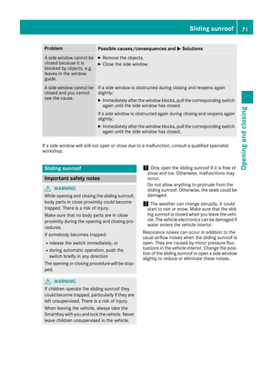 73
73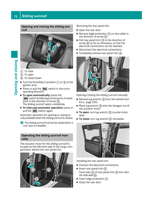 74
74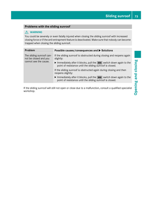 75
75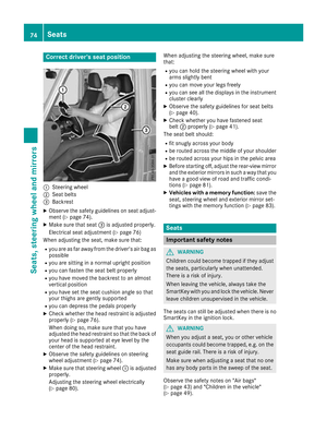 76
76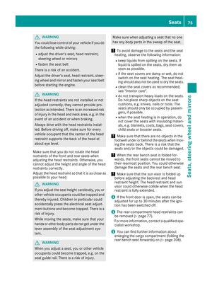 77
77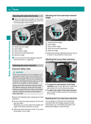 78
78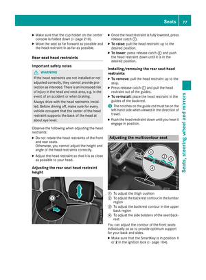 79
79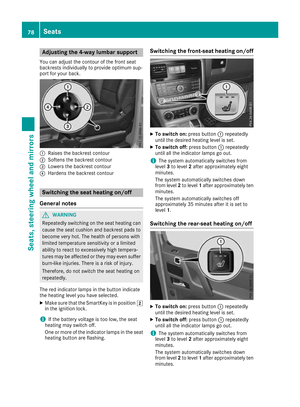 80
80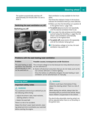 81
81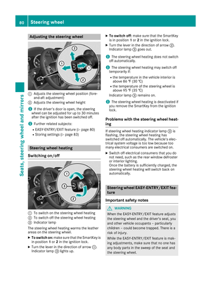 82
82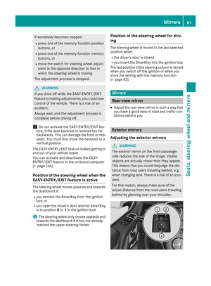 83
83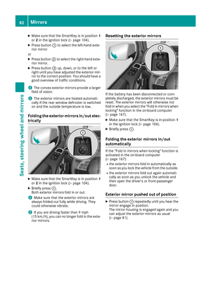 84
84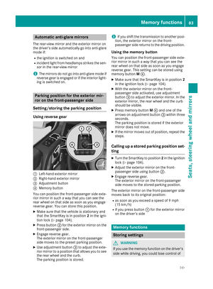 85
85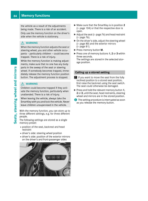 86
86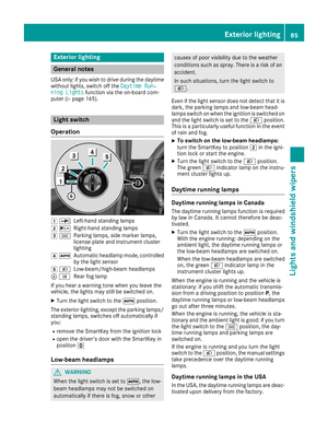 87
87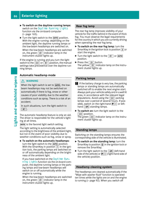 88
88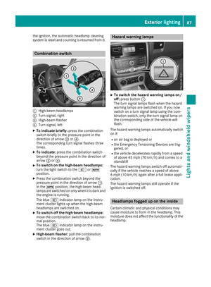 89
89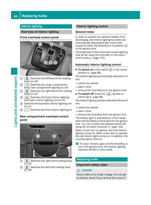 90
90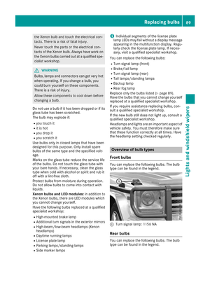 91
91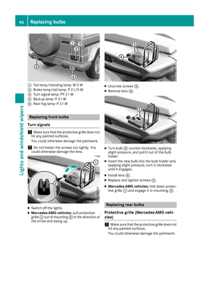 92
92 93
93 94
94 95
95 96
96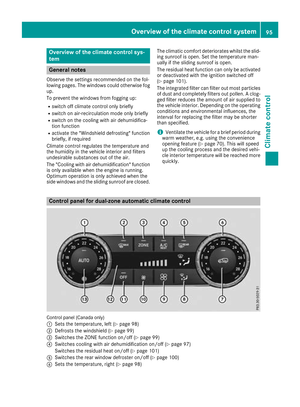 97
97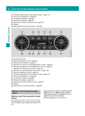 98
98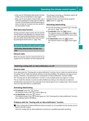 99
99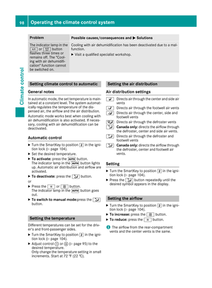 100
100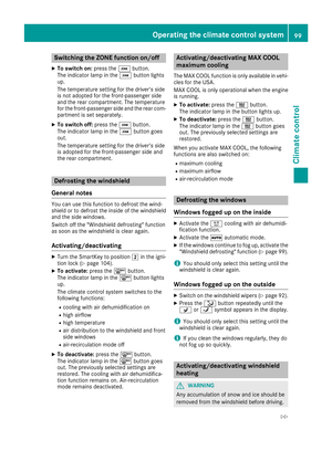 101
101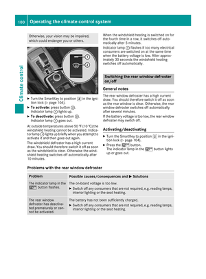 102
102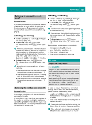 103
103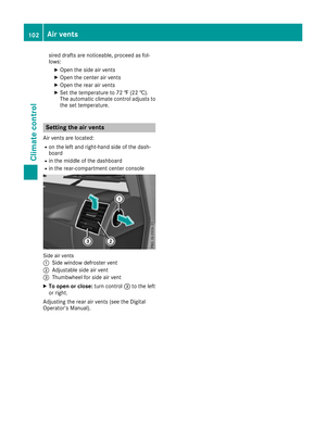 104
104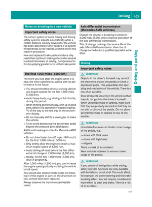 105
105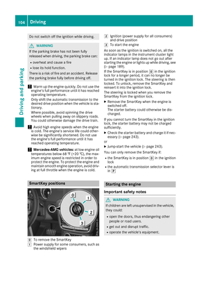 106
106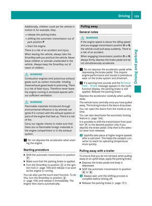 107
107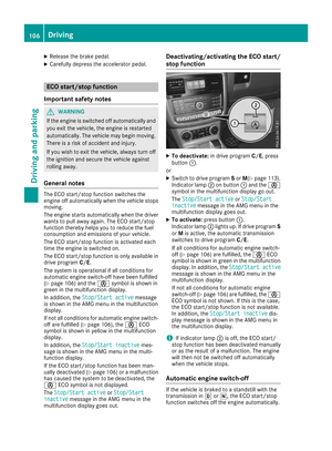 108
108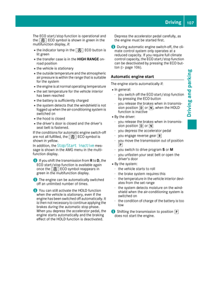 109
109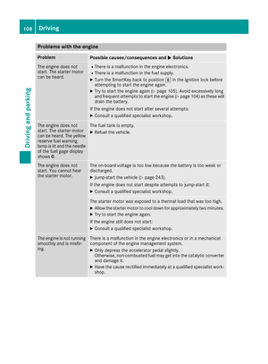 110
110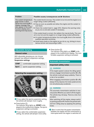 111
111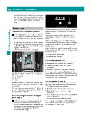 112
112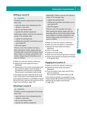 113
113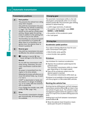 114
114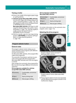 115
115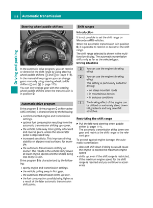 116
116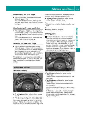 117
117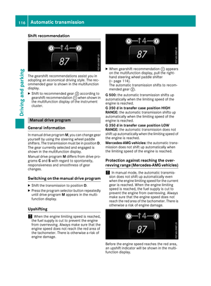 118
118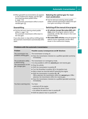 119
119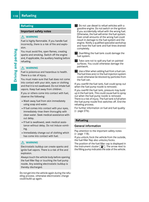 120
120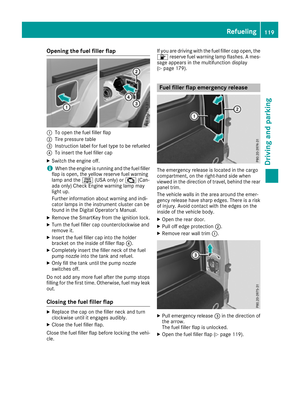 121
121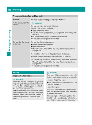 122
122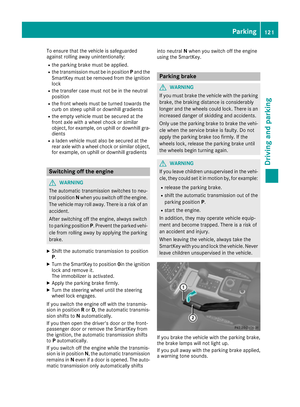 123
123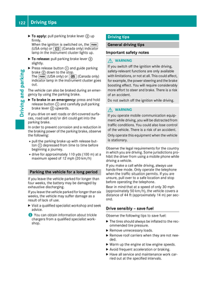 124
124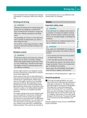 125
125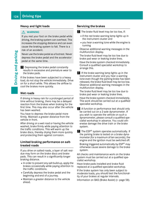 126
126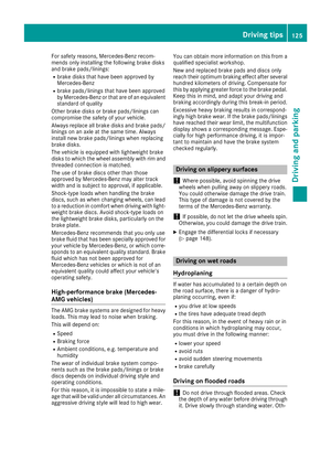 127
127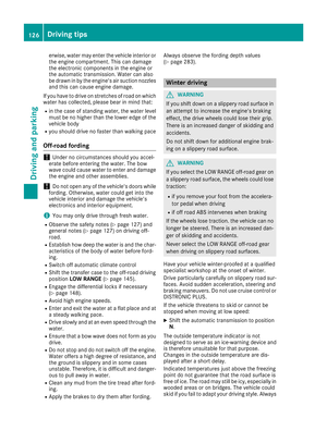 128
128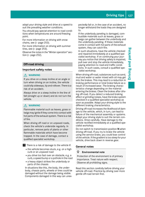 129
129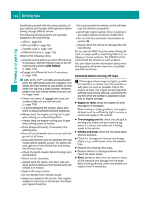 130
130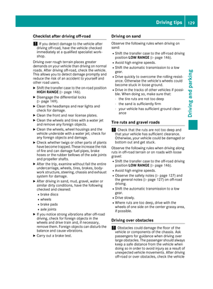 131
131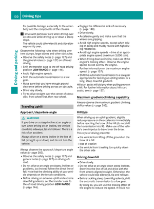 132
132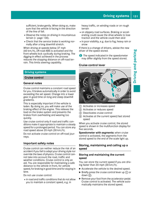 133
133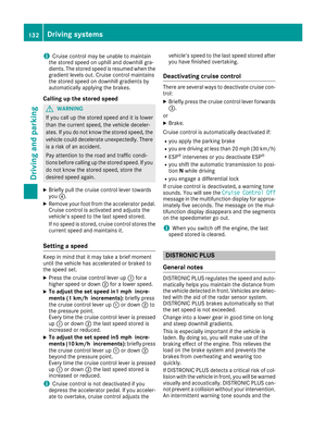 134
134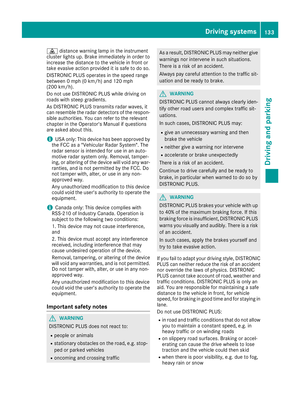 135
135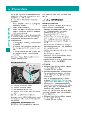 136
136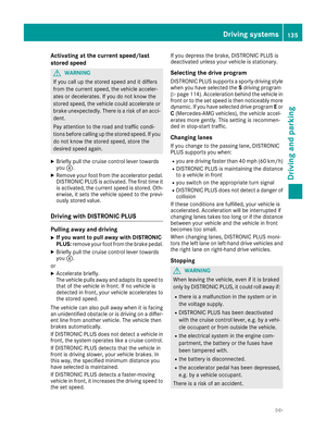 137
137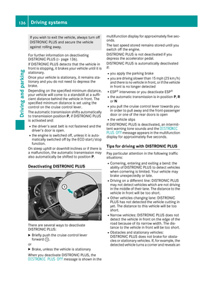 138
138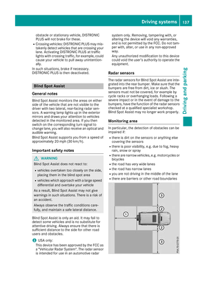 139
139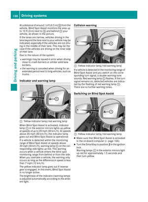 140
140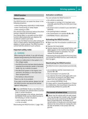 141
141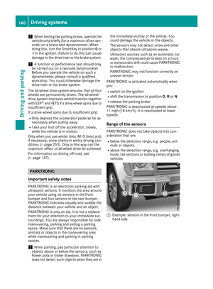 142
142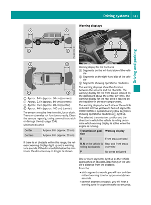 143
143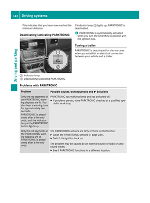 144
144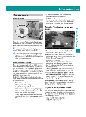 145
145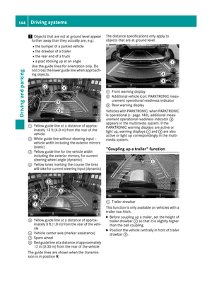 146
146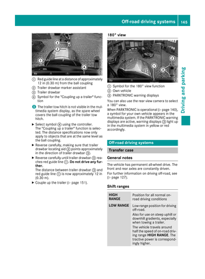 147
147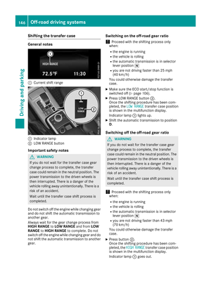 148
148 149
149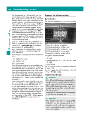 150
150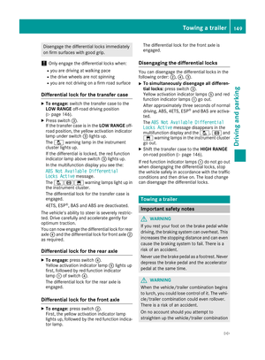 151
151 152
152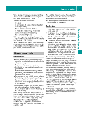 153
153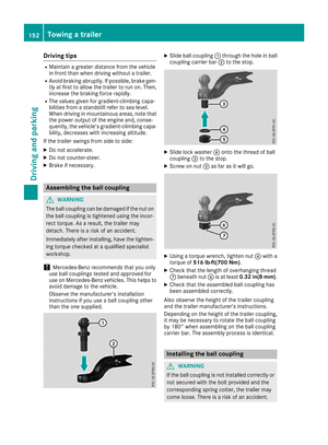 154
154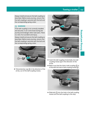 155
155 156
156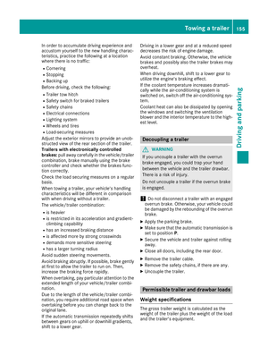 157
157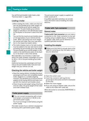 158
158 159
159 160
160 161
161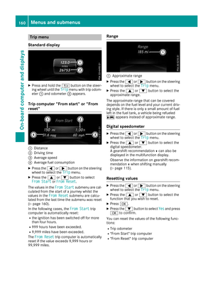 162
162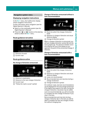 163
163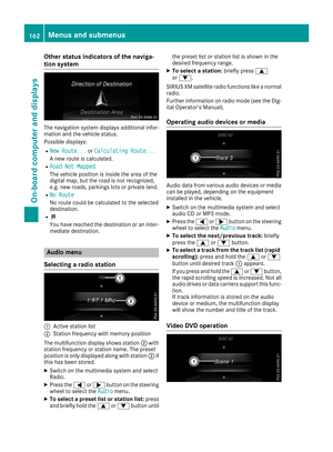 164
164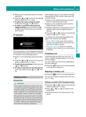 165
165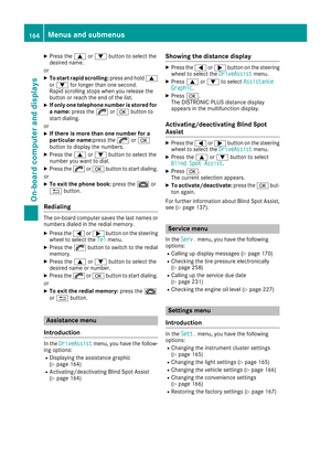 166
166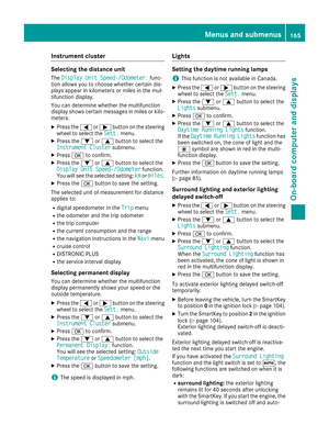 167
167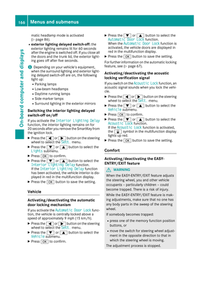 168
168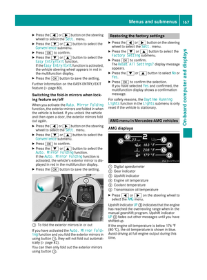 169
169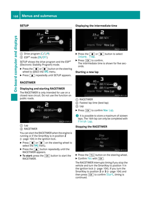 170
170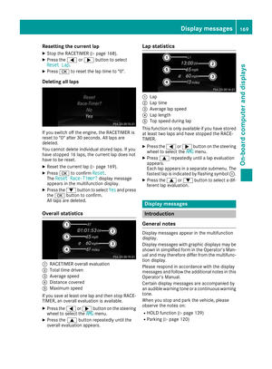 171
171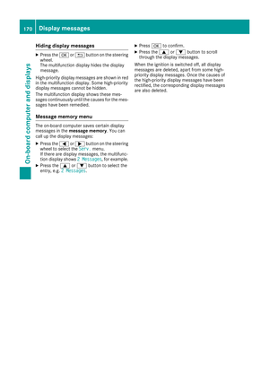 172
172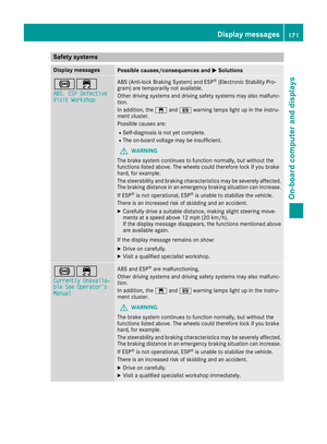 173
173 174
174 175
175 176
176 177
177 178
178 179
179 180
180 181
181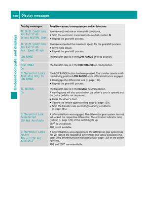 182
182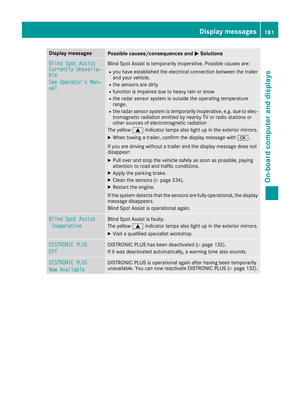 183
183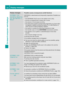 184
184 185
185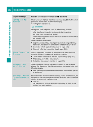 186
186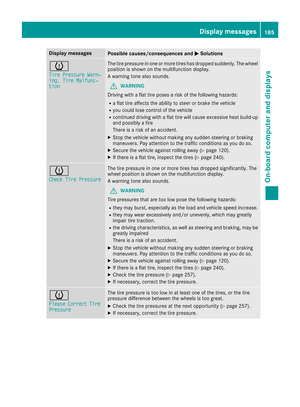 187
187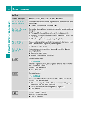 188
188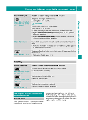 189
189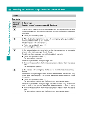 190
190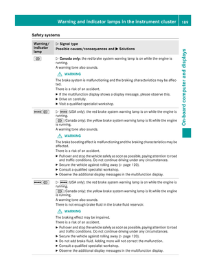 191
191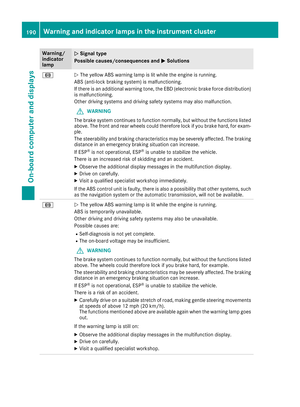 192
192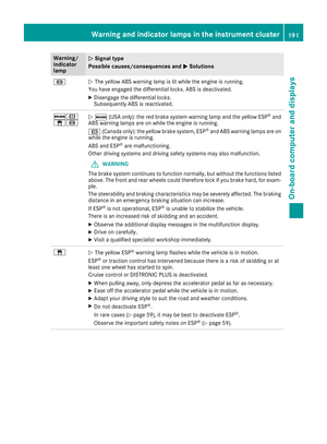 193
193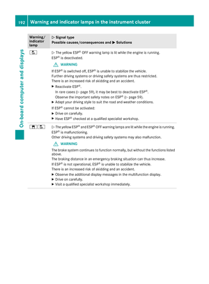 194
194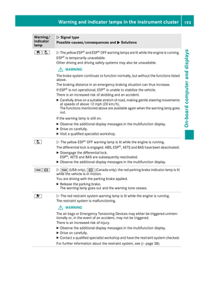 195
195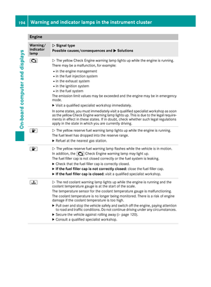 196
196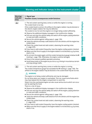 197
197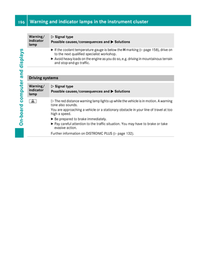 198
198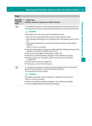 199
199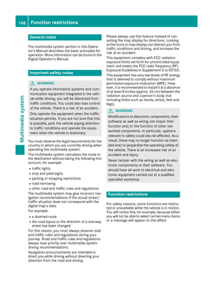 200
200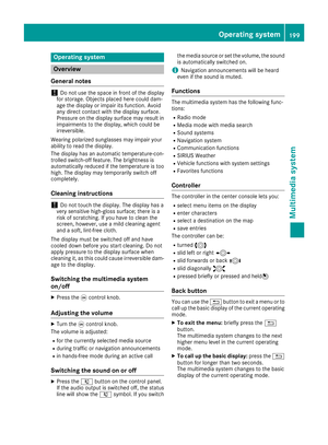 201
201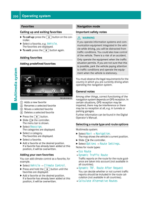 202
202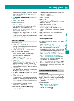 203
203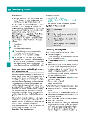 204
204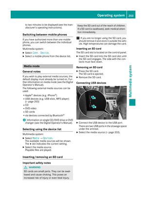 205
205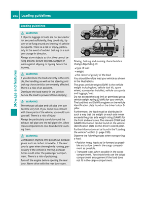 206
206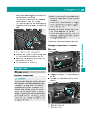 207
207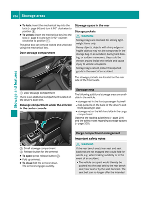 208
208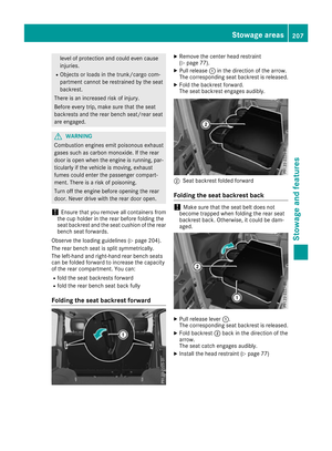 209
209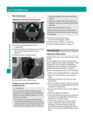 210
210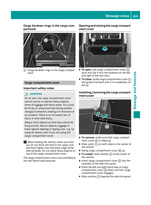 211
211 212
212 213
213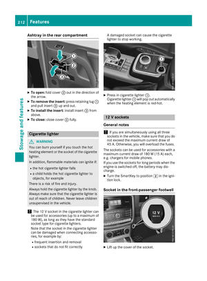 214
214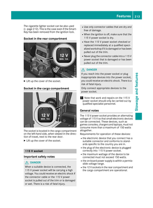 215
215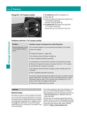 216
216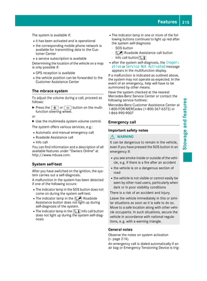 217
217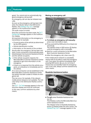 218
218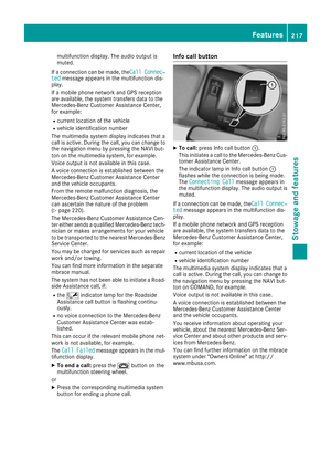 219
219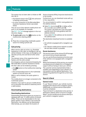 220
220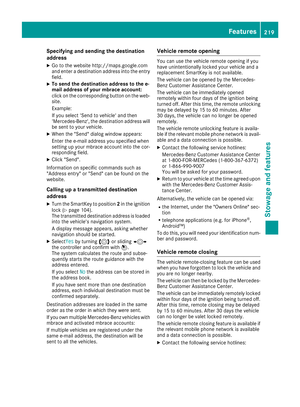 221
221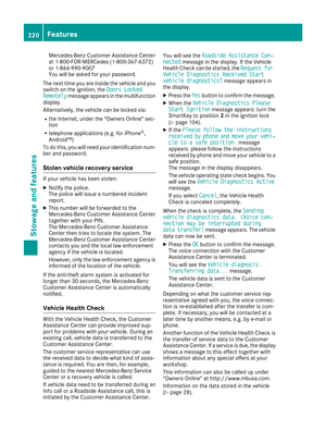 222
222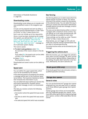 223
223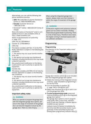 224
224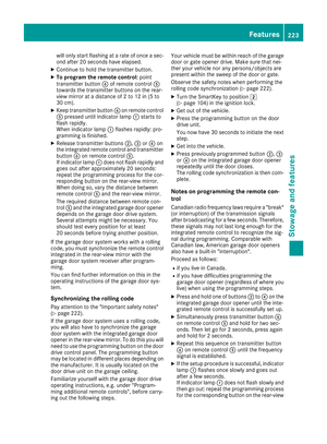 225
225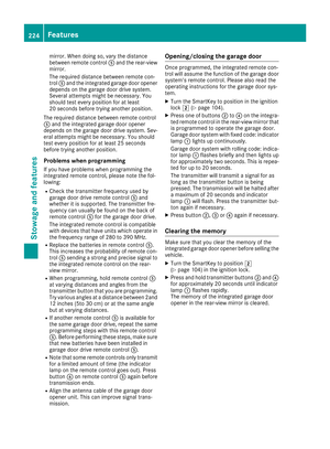 226
226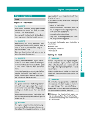 227
227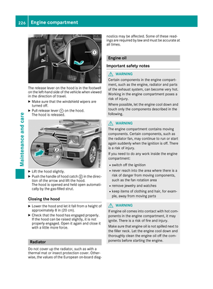 228
228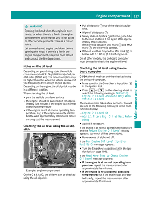 229
229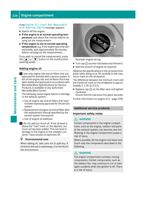 230
230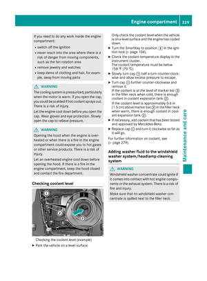 231
231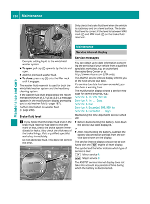 232
232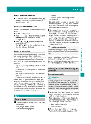 233
233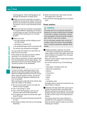 234
234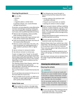 235
235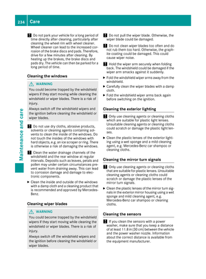 236
236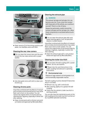 237
237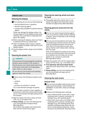 238
238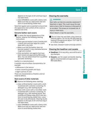 239
239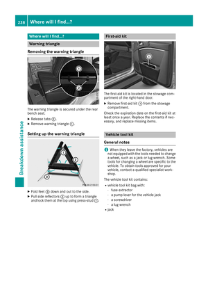 240
240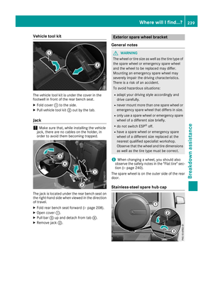 241
241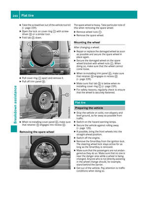 242
242 243
243 244
244 245
245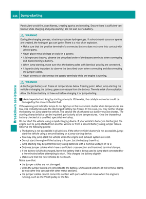 246
246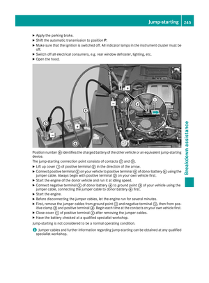 247
247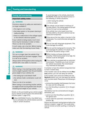 248
248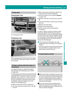 249
249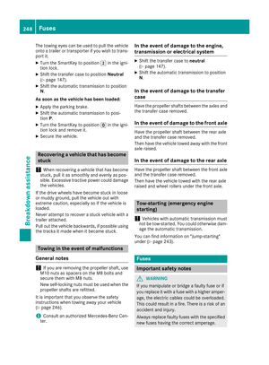 250
250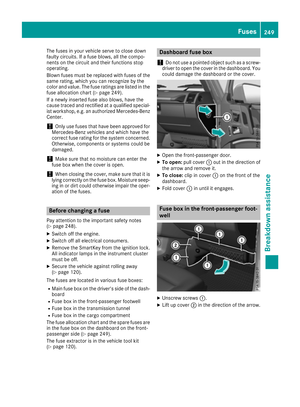 251
251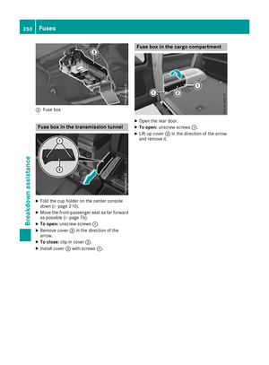 252
252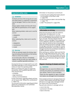 253
253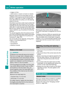 254
254 255
255 256
256 257
257 258
258 259
259 260
260 261
261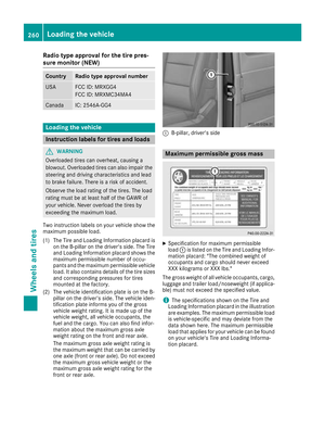 262
262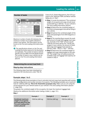 263
263 264
264 265
265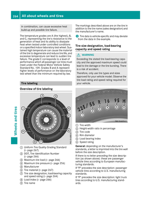 266
266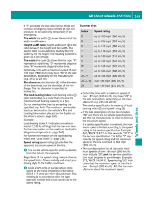 267
267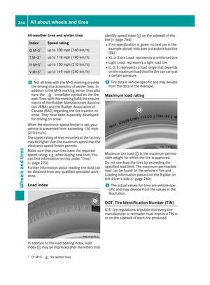 268
268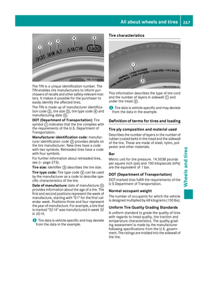 269
269 270
270 271
271 272
272 273
273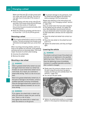 274
274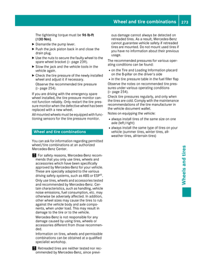 275
275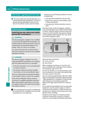 276
276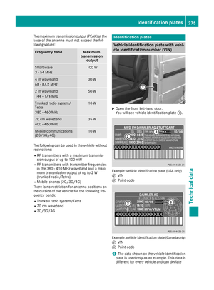 277
277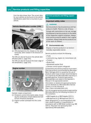 278
278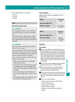 279
279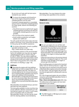 280
280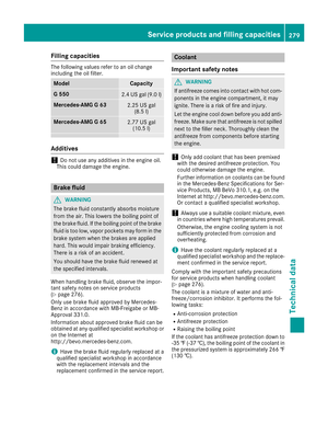 281
281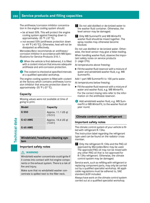 282
282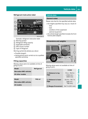 283
283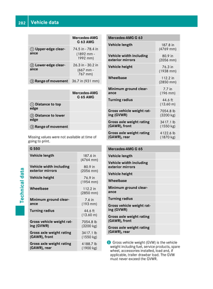 284
284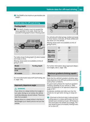 285
285