2017 MERCEDES-BENZ E-CLASS SALOON ignition
[x] Cancel search: ignitionPage 109 of 497

R
you open the driver's door when the ignition
is switched on
The steering wheel mo ves back tothe last drive
position in thefo llowing cases:
R you swit chthe ignition on when the driver's
door is closed
R you close the driver's door when the ignition
is switched on
The last drive position of thesteering wheel is
st ored in thefo llowing situations:
R you swit ch the ignition off
R Vehicles with memory function: save the
seat settings via the memory function.
Ve hicles with memory function: press one of
th e memory function sa ved position buttons to
st op the adjustment process.
Setting the easy entry and exitfeature
Multimedia sy stem:
, Vehicle .
Vehicle settings .
Easy
Entry/Exit #
Activate Oor deacti vate ª the function. Using
the memory function &
WARNING Risk of an accident if memo ry
function is used while driving
If yo u use the memory function on the driv‐
er's side while driving, you could lose cont rol
of theve hicle as a result of the adjustments
being made. #
Only use the memory function on the
driver's side when theve hicle is station‐
ar y. &
WARNING Risk of entrapment when set‐
ting the seat with the memory function
If yo u use the memory function toset the
seat or thesteering wheel, you and other
ve hicle occupants, especially children, could
be ent rapped. #
During the setting procedure of the
memory function, ensure that no body
parts are in the sweep of the seat or
th esteering wheel. #
If somebody becomes trapped, immedi‐
ately release the memory function posi‐
tion button.
The adjustment process is stopped. &
WARNING Risk of entrapment if the
memory function is activated bychildren
Children could become trapped if they acti‐
va te the memory function, particularly when
unattended. #
Never lea vechildren unat tended in the
ve hicle. #
When leaving theve hicle, alw aysta ke
th eke y with you and lock theve hicle.
This also applies tomobile phones if the
"Digital Car Key in the smartphone"
function is activated via the Mercedes
connect me web app. The memory function can be used when
the igni‐
tion is switched off. 106
Seats and stowing
Page 124 of 497
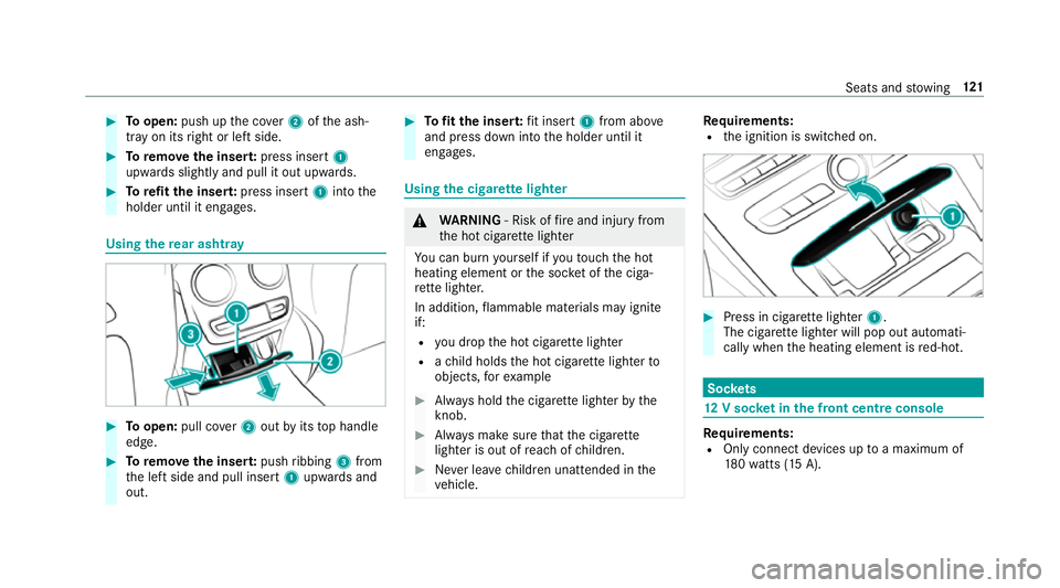
#
Toopen: push up the co ver2 ofthe ash‐
tray on its right or left side. #
Toremo vethe inser t:press insert 1
upwards slightly and pull it out upwards. #
Torefit the inse rt:press insert 1into the
holder until it engages. Using
there ar ashtr ay #
Toopen: pull co ver2 out byits top handle
edge. #
Toremo vethe inser t:push ribbing 3from
th e left side and pull insert 1upwards and
out. #
Tofit the inse rt:fi t insert 1from ab ove
and press down into the holder until it
engages. Using
the cigar ette lighter &
WARNING ‑ Risk of fire and injury from
th e hot cigar ette lighter
Yo u can burn yourself if youto uch the hot
heating element or the soc ket of the ciga‐
re tte lighter.
In addition, flammable materials may ignite
if:
R you drop the hot cigar ette lighter
R ach ild holds the hot cigar ette lighter to
objects, forex ample #
Alw ays hold the cigar ette lighter bythe
knob. #
Alw ays make sure that the cigar ette
lighter is out of reach of children. #
Never lea vechildren unat tended in the
ve hicle. Re
quirements:
R the ignition is switched on. #
Press in cigar ette lighter 1.
The cigar ette lighter will pop out automati‐
cally when the heating element is red-hot. Soc
kets 12
V so cket inthe front centre console Re
quirements:
R Only connect devices up toa maximum of
18 0wa tts (15 A). Seats and
stowing 121
Page 125 of 497
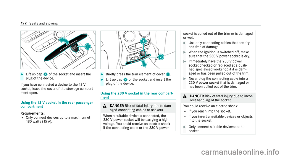
#
Lift up cap 1ofthe soc ket and insert the
plug of the device.
If yo u ha veconnected a device tothe12 V
soc ket, le ave the co ver of thestow age compart‐
ment open. Using
the12 V so cket inthere ar passenger
comp artment Re
quirements:
R Only connect devices up toa maximum of
18 0wa tts (15 A). #
Brie fly press the trim element of co ver2. #
Lift up cap 1ofthe soc ket and insert the
plug of the device. Using
the 230 V soc ket in the rear comp art‐
ment &
DANG ER Risk of fata l injury due todam‐
aged connecting cables or soc kets
When a suitable device is connected, the
230 V power soc ket will be car rying a high
vo ltage. You could recei vean electric shock
if th e connecting cable or the 230 V po wer soc
ket is pulled out of the trim or is damaged
or we t. #
Use only connecting cables that are dry
and free of damage. #
When the ignition is switched off, make
sure that the 230 V po wer soc ket is dr y. #
Immedia tely ha ve the 230 V po wer
soc ketch ecked or replaced at a quali‐
fi ed specialised workshop if it is dam‐
aged or has been pulled out of the trim. #
Never plug the connecting cable into a
230 V po wer soc ketth at is damaged or
has been pulled out of the trim. &
DANG ER Risk of fata l injury due toincor‐
re ct handling of the soc ket
Yo u could recei vean electric shock:
R ifyo ure ach into the soc ket.
R ifyo u insert unsuitable devices or objects
into the soc ket. #
Only connect suitable devices tothe
soc ket. 12 2
Seats and stowing
Page 127 of 497
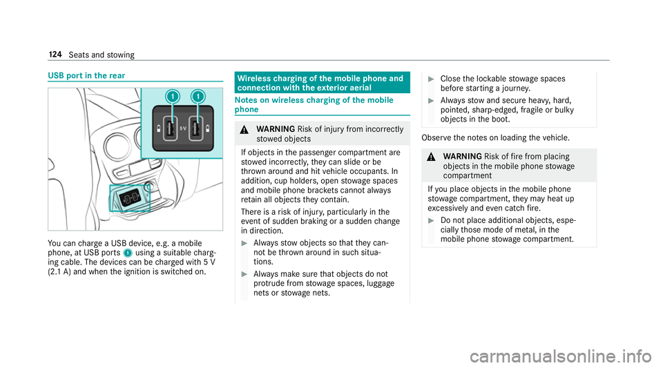
USB port in
there ar Yo
u can charge a USB device, e.g. a mobile
phone, at USB ports 1using a suitable charg‐
ing cable. The devices can be charge d with 5 V
(2.1 A) and when the ignition is switched on. Wire
lesscharging of the mobile phone and
connection with theex terior aerial Note
s on wireless charging of the mobile
phone &
WARNING Risk of inju ryfrom incor rectly
stowe d objects
If objects in the passenger compartment are
stowe d incor rectl y,they can slide or be
th ro wn around and hit vehicle occupants. In
addition, cup holders, open stowage spaces
and mobile phone brac kets cann otalw ays
re tain all objects they contain.
The reis a risk of injur y,particularly in the
ev ent of sudden braking or a sudden change
in direction. #
Alw aysstow objects so that they can‐
not be throw n around in su chsitua‐
tions. #
Alw ays make sure that objects do not
pr otru de from stowage spaces, luggage
nets or stowage nets. #
Close the loc kable stow age spaces
before starting a journe y. #
Alw aysstow and secure heavy, hard,
poin ted, sharp-edged, fragile or bulky
objects in the boot. Obser
vethe no tes on loading theve hicle. &
WARNING Risk offire from placing
objects in the mobile phone stowage
compartment
If yo u place objects in the mobile phone
stow age compartment, they may heat up
exc essively and even catch fire. #
Do not place additional objects, espe‐
cially those mode of me tal, in the
mobile phone stowage compartment. 124
Seats and stowing
Page 128 of 497
*
NO
TEDama getoobjects caused by
placing them in the mobile phone stow‐
age compartment If
yo u place objects in the mobile phone
stow age compartment, these may be dam‐
aged byelectromagnetic fields. #
Do not place credit cards, storage
media or other objects sensitive to
electromagnetic fields in the mobile
phone stowage compartment. *
NO
TEDama getothe mobile phone
stow age compartment caused byliquids If liquids enter
the mobile phone stowage
compartment, the compartment may be
damaged. #
Ensure that no liquids enter the mobile
phone stowage compartment. R
Depending on theve hicle equipment, the
mobile phone is connected totheve hicle's
ex terior aerial via thech arging module. R
The charging function and wireless connec‐
tion of the mobile phone totheve hicle's
ex terior aerial are only available if the ignition
is switched on.
R Small mobile phones may not be able tobe
ch arge d in everyposition of the mobile
phone stowage compartment.
R Largemobile phones which do not rest flat in
th e mobile phone stowage compartment may
not be able tobe charge d or connec ted with
th eve hicle's exterior aerial.
R The mobile phone may heat up during the
ch arging process. This depends on the appli‐
cations (apps) cur rently running.
The mobile phone can be cooled in the
mobile phone stowage compartment when
th e air conditioning sy stem is switched on.
The cooling output in the mobile phone stow‐
age compartment is highest when the con‐
troller in theglove box is closed.
R Toensure more ef ficient charging and con‐
nection with theve hicle's exterior aerial,
re mo vethe pr otective co ver from the mobile phone. Pr
otective co vers which are designed
fo r wireless charging are excluded.
R When charging, the mat should be used if
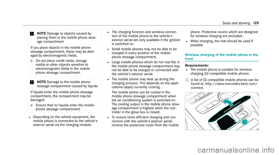
possible. Wire
lesscharging of the mobile phone in the
front Requ
irements:
R The mobile phone is suitable for wireless
ch arging (Qi compatible mobile phone).
% A list of Qi compatible mobile phones can be
fo und at: http://www.mercedes-benz.com/
connect. Seats and
stowing 12 5
Page 131 of 497

5
L Dipped beam/main beam
6 R Switches there ar fog light on or off
When dipped beam is activated, the indicator
lamp forth est anding lights Tis deactivated
and replaced bythe dipped beam indicator lamp
L. #
Alw ays park your vehicle safely and in a well-
lit area, in accordance with there leva nt le gal
st ipulations.
* NO
TEBattery discharging byoperating
th est anding lights Operating
thest anding lights over a period of
hours puts a stra in on the batter y. #
Where possible, switch on the
ri ght X or left Wparking light. In
the case of se vere battery discharging, the
st anding lights or parking lights are automati‐
cally swit ched off tofacilitate the next engine
st art. The
exterior lighting (e xcept standing and park‐
ing lights) swit ches off automatically when the
driver's door is opened.
R Obser vethe no tes on sur round lighting .
Au tomatic driving lights function
The standing lights, dipped beam and daytime
ru nning lights are switched on au tomatical ly
depending on the ignition status, whe ther the
engine is running and the light conditions. &
WARNING Risk of accident when the
dipped beam is switched off in poor visi‐
bility
When the light switch is set toà ,the
dipped beam may not be switched on auto‐
matically if there is fog, snow or other causes
of poor visibility such as spr ay. #
In such cases, turn the light switch to
L . The automatic driving lights are only an aid.
Yo u
are responsible forve hicle lighting. Ac
tivating/deactivating the rear fog light
Re quirements:
R The light switch is in the L orà posi‐
tion. #
Press the R button.
Please obser vethe count ry-specific la wsonthe
use of rear fog lamps.
Ad justing the headlamp range (halogen
headla mps without active suspension)
The headlamp range adjus ter allows youto
adjust the cone of light from the headlamps in
re lation totheve hicle's load condition. 12 8
Light and sight
Page 135 of 497

R
The GPS.
The function is not active: R Atspeeds below 80 km/h.
Enhanced fog light function
The enhanced fog light function reduces glare
fo rth e driver and impr ovesth e illumination of
th e edge of the car riag ewa y. The function is active:
R Atspeeds below 70 km/h when there ar fog
light is switched on.
The function is not active:
R Atspeeds abo ve100 km/h af ter activation. R
When there ar fog light is switched off.
Ad versewe ather light function
The adverse weather light reduces reflections in
ra iny conditions bydimming individual LEDs in
th e headlamps. This reduces theglare forthe
driver and other road users.
Fu nction of City lighting
City lighting impr ovesth e illumination of road‐
sides within built-up areas using a broader distri‐
bution of light.
The function is active:
R at lo wer speeds
R in illumina ted parts of built-up areas.
Switching the Intelligent Light Sy stem
on/off
Requ irements:
th e ignition is switched on.
Multimedia sy stem:
, Vehicle .
Lights .
Intelligent Light Sys-
tem #
Switch the function on or off. Ad
aptive Highbeam Assist Fu
nction of Adaptive Highbeam Assist &
WARNING Risk of accident despi te
Ad aptive Highbeam Assist
Ad aptive Highbeam Assist does not recog‐
nise thefo llowing road users:
R Road users without lights, e.g. pedes‐
trians
R Road users with poor lighting, e.g.
cyclists
R Road users whose lighting is obstructed,
e.g. bya bar rier
On very rare occasions, Adaptive Highbeam
Assist may failto recognise other road users
with their own lighting, or may recognise
th em too late.
In this, or in similar situations, the automatic
main beam will not be deactivated or will be
activated despite the presence of other road
users. 13 2
Light and sight
Page 143 of 497
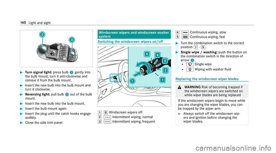
#
Turn signal light: press bulb2gently into
th e bulb mount, turn it anti-clockwise and
re mo veit from the bulb mount. #
Insert the new bulb into the bulb mount and
turn it clockwise. #
Reversing light: pull bulb3out of the bulb
mount. #
Insert the new bulb into the bulb mount. #
Insert the bulb mount again. #
Insert the plug until the catch hooks engage
audibl y. #
Close the side trim panel. Wi
ndscreen wipers and windscreen washer
sy stem Switching
the windscreen wipers on/off 1
gWindsc reen wipers off
2 Ä Intermittent wiping, normal
3 Å Intermittent wiping, frequent 4
° Continuous wiping, slow
5 ¯ Continuous wiping, fast #
Turn the combination switch tothe cor rect
position 1-5. #
Single wipe / washing: pushthe button on
th e combination switch in the direction of
ar row 1.
R í Single wipe
R î Wiping with washer fluid Re
placing the windsc reen wiper blades &
WARNING Risk of becoming trapped if
th e windscreen wipers are switched on
while wiper blades are being replaced
If th e windscreen wipers begin tomo vewhile
yo u are changing the wiper blades, you can
be trapped bythe wiper arm. #
Alw ays switch off the windscreen wip‐
ers and ignition before changing the
wiper blades. 14 0
Light and sight