Page 65 of 80

122 || 123
HANDLING THE UNEXPECTED
HANDLING THE UNEXPECTED
Tire Repair Kit
If a tire has a small puncture, you can use the tire repair kit to tempo\
rarily repair it.
The puncture must be smaller than 3/16-inch (4 mm) and not in the tire\
sidewall. Go
to a dealer to have the full-size tire permanently repaired or replaced.\
This vehicle is
not equipped with a spare tire.
Before Repairing the Tire
1.
Park the vehicle on a firm, level, and non-slippery surface.
2.
Move the shift lever to Park (P).
3.
Turn on the hazard warning lights and set the power mode to veHICLe oFF
(L
oCK).
Getting Ready to Repair the Tire
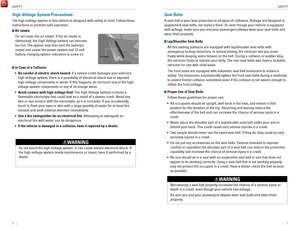
1.
open the trunk floor lid and take the kit out of the
case.
2.
Place the kit upright on flat ground near the
punctured tire and away from traffic. Do not place
the kit on its side.
3.
Follow the instructions in the kit to repair the tire.
If the required air pressure is not reached within 10 minutes, the tire \
may be too
severely damaged for the kit to provide the necessary seal and your vehi\
cle will need to be towed.
Do not operate the temporary tire repair kit compressor for more than 15\
minut
es.
The accessory power socket and compressor can overheat and become
permanently damaged.
NOTICE
running the engine with the vehicle in an enclosed or even partly enclose\
d
area can cause a rapid build-up of toxic carbon monoxide.
Breathing this colorless, odorless gas can cause unconsciousness and even
death.
only run the engine to power the air compressor with the vehicle
outdoors.
WARNING
Trunk Floor Lid
Tire repair Kit
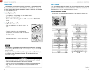
Fuse Locations
If any electrical devices are not working, turn the vehicle off and chec\
k to see if any
applicable fuse is blown. Fuse locations are shown on the fuse box cover\
. Locate the
fuse in question by the fuse number and box cover number.
Engine Compartment Fuse Box
Located under the hood near the 12-volt battery. Push the tabs to open the box.
*if equipped
Circuit ProtectedAmps
1Battery15 0A
2ePS70 A
eS B40 Aright ePB*(30A )40 A
Fuse Box option 1Shift By Wire*(30A )
rF C4 0A
IG Main 1
3 0A
3
Headlight Low Beam Main 30Aengine electric Water Pump3 0AIG Main 230AWiper Moto r
4 3
0A
FI Main15 A5 PCU electric Water Pump
6 7.
5A
ev TC20 A
710 A
815 A
915 A
1010 A
11
12
10 A rear Defogger
60
A
Fuse Box Main 1 50 A
ABS/vSA FSr 60
A
IG Hol d
DBW
IG Coi l
Stop Light vBU Fuse Box Main 2
40A
Fuse Box
ABS/vSA Motor 3
0A
3 0A
Heater Motor 40A
Left ePB
*
Small Light (3
0A )
20 A40 A
13(40 A)
14(4 0A )
15
16 (1
0A )10A
1715 A
AmpsCircuit Protected
Fuse Box option 2
A/C PTC 4
A/CPTC 2
Front Fog Light + Dr L
Horn
IG Hold 3-L/r
18 Interior Light7. 5A
19−−
20 (20 A)Premium Amp*
21Back Up
22 10
A
Audio15 A
23P-ACT Drive*(7.5 A)
10 A
25 Left Headlight Low Beam26
24 right Headlight Low Bea m10 A
IGPS LAF10 A
Page 66 of 80

124 || 125
HANDLING THE UNEXPECTED
HANDLING THE UNEXPECTED
Interior Fuse Box
Located under the dashboard on the driver’s side.
*if equipped
Amps1Circuit Protecte d
A/C7.5 A2DrL7.5 A
3−−4−−5Meter10 A6SrS(7.5A )
7option(7.5A )
8−−9Fuel Pump20 A10ABS/vSA7.5A
11vB SoL10 A12Front Wipe r7.5A
13ACG10 A
14rear Accessory Power Socket20 A
15
reclining
(Console Compartment)
Driver’s Power Seat (20 A)
16
Moonroof*(20 A)
17Front Seat Heaters(20 A)
18−−
19Passenger Side Door 10 A
20
Unlock
Unlock
Driver Side rear Door 10A 21
Driver’s Door Lock10
A22 Passenger Side Door Loc k10A23Driver’s Door Unlock10A24SrS10A25Illumination10A
26Key Loc k7.5A
27Parking Lights10 A
28Lumbar Suppor t(10 A)
30Washer
29
right Headlight High Bea m10A15A
31A/C Main10 A32 Driver’s Power Window20A
Circuit Protected Amps
33Front Passenger’s Power 20A
34Window
rear Driver Side Power
20 A
35
Window
rear Passenger Side Power
20A
37ACCeSSorY7.5A
Window
36 Driver’s Power Seat Sliding (20A)
38
−−39 Left Headlight High Beam10A
40
Socket20 AFront Accessory Power
42
(Console Panel )
41 Driver Side rear Door Lock 10A
Door Lock20Aa10Ab(7.5A )
c10 A
d15 A
e
SMArT
SHIFTe r*
Hybrid System
Hazard
Passenger's Power Seat
f (20
A)
g (20
A)h (15
A)i (15
A)−j7.5A
reclinin
g
*
Passenger's Power Seat
Sliding*
rear Seat Heaters*
ACL*
−
IG MoN*
Fuse label
Inspecting and Changing Fuses
1.
Turn the vehicle off, including all lights and
accessories.
2.
remove the fuse box cover.
3.
Check the large fuse in the engine compartment.
If the fuse is blown, use a Phillips-head
screwdriver to remove the screws and replace
the fuse with a new one.
reinstall the screws.
4.
Inspect the small fuses in the engine
compartment and the vehicle interior.
If there is a burned out fuse, remove it with the
fuse puller and replace it with a new one.
Combined
fuse Blown fuse
Fuse puller
replacing a fuse with one that has a higher rating greatly increases the \
chances of
damaging the electrical system.
NOTICE
Page 67 of 80

126 || 127
M
AINTENANCEMAINTENANCE
MAINTENANCE
Learn about basic maintenance that you can perform on the vehicle yourse\
lf, as well
as information about how to best maintain the vehicle.
Safety Precautions
Some of the most important safety precautions are listed below; however, we cannot
warn you of every conceivable hazard that can arise in performing mainte\
nance.
only you can decide whether or not you should perform a given task.
Maintenance Safety
•
To reduce the possibility of fire or explosion, keep cigarettes, sparks\
, and flames
away from the 12-volt battery and all fuel-related parts.
•
Never leave rags, towels, or other flammable objects under the hood. H\
eat from
the engine and exhaust can ignite them, causing a fire.
•
To clean parts, use a commercially available degreaser or parts cleaner, not
gasoline.
•
Wear eye protection and protective clothing when working with the 12-volt\
battery or compressed air.
•
Do not run the engine in confined spaces where carbon monoxide gas can\
accumulate.
Vehicle Safety
•
The vehicle must be stationary, and parked on level ground with the parking
brake set and the power system off.
•
Be aware that hot parts can burn you.
•
Be aware that moving parts can injure you.
Improperly maintaining this vehicle or failing to correct a problem befo\
re driving can cause a crash in which you can be seriously hurt or killed. \
Always follow the inspection and maintenance recommendations according
to the schedules in this guide.
WARNING
Failure to properly follow maintenance instructions and precautions can \
cause you to be seriously hurt or killed.
Always follow the procedures and precautions in this guide.
WARNING
Maintenance Minder™
reminds you when indicated maintenance service is due.
When maintenance is due, the system message indicator comes on and a mes\
sage
appears on the multi-information display every time you turn the vehicle\
on. Press either Info (p
/q) button on the steering wheel to change displays.
•
Independent of the Maintenance Minder information, replace the brake fl\
uid every
3 years.
•
Inspect idle speed every 160,000 miles (256,000 km).
•
Adjust the valves during services A, B, 1, 2, or 3 if they are noisy.
Maintenance Minder
messag e
System message
indicator
Sub items
Main item
U.S. models
Maintenance, replacement, or repair of emissions control devices and sys\
tems
may be done by any automotive repair establishment or individuals using \
parts
that are certified to EPA standards.
According to state and federal regulations, failure to perform maintenan\
ce on the
maintenance main items marked with # will not void your emissions warranties.
However, all maintenance services should be performed in accordance with the
intervals indicated by the multi-information display.
Page 68 of 80

128 || 129
M
AINTENANCEMAINTENANCE
Maintenance Minder Service Codes
These codes indicate what services are due on your vehicle.
*1: If a message Service does not appear more than 12 months after the display is reset, change \
the
CoDe
engine oil every year.
#: See information on maintenance and emissions warranty.
A�
Maintenance Main Items
B�
replace engine oil*1
�
�Inspect front and rear brakes/service as necessary
�
Check parking brake adjustment replace engine oil
*1 and oil filter
�
�
Inspect tie rod ends, steering gearbox, and boots
�
Inspect suspension components
Inspect driveshaft boots
�
Inspect brake hoses and lines (Including ABS/vSA)
�
�Inspect exhaust system#Inspect all fluid levels and condition of fluids
�
Inspect fuel lines and connection s#
*
Check expiration date for TrK bottle
*2: If you drive in dusty conditions, replace the air cleaner element every \
15,000 miles (24,000 km).
* from diesel-powered vehicles, replace the dust and pollen filter every\
15,000 miles (24,000 km).
3:
If you drive primarily in urban areas that have high concentrations of s\
oot in the air from industry and
4: Driving in mountainous areas at very low vehicle speeds results in highe\
r transmission temperatures.
CoDe
1�
Maintenance Sub Items
rotate tires
2
This requires transmission fluid changes more frequently than recommen\
ded by the Maintenance
Minder. If you regularly drive your vehicle under these conditions, have the transmission fluid c hanged every 47,500 miles (75,000 km) or 3 years.
�
�replace air cleaner element*2
3�
replace dust and pollen filter*3
4�
replace transmission fluid*4
�Inspect valve clearance
5
�
replace spark plugs
replace engine coolant
Under the Hood
Br ake Fluid
(Black Cap)
engine Coolant
reserve Tank radiator Cap
Washer Fluid
(Blue Cap) engine oil Dipstick
(orange)
12-volt Batter y
engine oil Fill Cap
Inverter Coolant
Filler Tank
Opening the Hood
1.
Park the vehicle on a level surface, and set the
parking brake.
2.
Pull the hood release handle under the lower left
corner of the dashboard.
3.
Push up the hood latch lever in the center of the
hood to release the lock mechanism, and open
the hood.
4.
remove the support rod from the clamp using the
grip. Mount the support rod in the hood.
When closing, remove the support rod, and
stow it in the clamp, then gently lower the hood.
remove your hand at a height of approximately
12 inches (30 cm) and let the hood close.
Do not open the hood when the wiper arms are raised. The hood will strik\
e the
wipers, and may damage either the hood or the wipers.
NOTICE
Hood release handle Pull
Lever
Support ro d
Grip
Clamp
Page 69 of 80

130 || 131
M
AINTENANCEMAINTENANCE
Engine Oil
Park the vehicle on level ground, and turn the power system off. Wait about three
minutes before you check the oil.
Checking the Oil
1.
remove the dipstick (orange).
2.
Wipe the dipstick with a clean cloth or paper
towel.
3.
Insert the dipstick back all the way into its hole.
4.
remove the dipstick again, and check the level.
It should be between the upper and lower marks.
Add oil if necessary.
Upper mark
Lower mark
Recommended Engine Oil
• Honda Genuine Motor Oil
•
Premium-grade 0W-20 detergent oil with an API Certification Seal on the
container
This seal indicates the oil is energy conserving and
that it meets the American Petroleum Institute’s
latest requirements.
Use Honda Genuine Motor
oil or another
commercial engine oil of suitable viscosity for the
ambient temperature as shown.
You may also use synthetic motor oil if it is labeled
with the API Certification Seal and is of the
specified viscosity grade.
Ambient temperature
Do not fill the engine oil above the upper mark. overfilling the engine oil can result
in leaks and engine damage.
NOTICE
Adding Oil
1.
Unscrew and remove the engine oil fill cap.
2.
Add oil slowly.
3.
reinstall the engine oil fill cap, and tighten it
securely.
4.
Wait for three minutes and recheck the engine oil
dipstick.
engine oil Fill Cap
Resetting the Engine Oil Life If you change or replace the vehicle’s engine oil yourself, you must reset the
engine oil life.
Use the Info (p/q) and S
eL/reSeT buttons on the steering wheel buttons to
control the display.
1.
Scroll to the vehicle Settings screen, and select
it.
2.
Scroll to the Maintenance reset screen, and
select it.
3.
Select reset. The maintenance codes disappear,
and the engine oil life display returns to 100%.
Failure to reset the Maintenance Minder™ display after a maintenance \
service
results in the system showing incorrect maintenance intervals, which can\
lead to
serious mechanical problems.
NOTICE
Page 70 of 80

132 || 133
M
AINTENANCEMAINTENANCE
Engine Coolant
Park the vehicle on level ground. Check the reserve tank and the coolant\
level in the
radiator. We recommend Honda Long Life Antifreeze/Coolant Type 2.
Checking the Reserve Tank
1.
Check the amount of coolant in the reserve tank.
2.
If the coolant level is below the MIN mark, add
the specified coolant until it reaches the MAX
mark.
3.
Inspect the cooling system for leaks.
Adding Coolant 1.
Make sure the engine and radiator are cool.
2.
Turn the radiator cap counterclockwise and
relieve any pressure in the cooling system. Do
not push the cap down when turning.
3.
Push down and turn the radiator cap
counterclockwise to remove it.
4.
The coolant level should be up to the base of the
filler neck. Add coolant if it is low.
5.
Put the radiator cap back on, and tighten it fully.
6.
Pour coolant into the reserve tank until it reaches
the MAX mark. Put the cap back on the reserve
tank.
engine
reserve Coolant
Tank
MAX
MIN
If temperatures consistently below −22°F (−30°C) are expec\
ted, the coolant
mixture should be changed to a higher concentration. Consult a dealer fo\
r details
for more information.
NOTICE
Tank
MAX
reserve
MIN
removing the radiator cap while the engine is hot can cause the coolant t\
o
spray out, seriously scalding you.
Always let the engine and radiator cool down before removing the radiato\
r
cap.
WARNING
Pour the fluid slowly and carefully so you do not spill any. Clean up any spills
immediately; they can damage components in the engine compartment.
NOTICE
Brake Fluid
The fluid level should be between the MIN and MAX marks on the side of\
the
reservoir. We recommend Honda Heavy Duty Brake Fluid DOT 3.
Pour the fluid carefully.
If the fluid level is at or below the MIN mark, have a
dealer inspect for leaks or worn brake pads as soon as
possible.
MIN
Brake reservoir
MAX
Brake fluid marked DoT 5 is not compatible with your vehicle’s braking system and
can cause extensive damage.
NOTICE
*if equipped
Inverter Coolant
The fluid level should be between the MIN and MAX marks on the side of\
the
reservoir. We recommend Honda Long Life Antifreeze/Coolant Type 2.
1.
When the inverter is cool, check the amount of
coolant in the filler tank.
2.
If the coolant level is below the MIN mark, add
the specified coolant until it reaches the MAX
mark.
3.
Inspect the cooling system for leaks.
MAXMIN
Filler
Tank
Page 71 of 80

134 || 135
M
AINTENANCEMAINTENANCE
Checking the 12-volt Battery
Check the battery terminals for corrosion monthly.
The battery condition is monitored by a sensor on the
negative terminal. If there is a problem with the sensor,
a message on the information multi-information display
appears. Have your vehicle checked by a dealer.
WARNING: Battery posts, terminals, and related accessories contain lead and lead\
compounds. Wash your hands after handling.
The battery gives off explosive hydrogen gas during normal operation.
A spark or flame can cause the battery to explode with enough force to\
kill or
seriously hurt you.
When conducting any battery maintenance, wear protective clothing and a \
face shield, or have a skilled technician do it.
WARNING
Window Washer Fluid
If the washer fluid level is low, fill the washer reservoir.
Pour the washer fluid carefully. Do not overflow the
reservoir.
Canadian models
If the washer fluid level is low, the washer level
indicator or a message appears on the multi-
information display.
Do not use engine antifreeze or a vinegar/water solution in the windshie\
ld washer
reservoir. Antifreeze can damage your vehicle’s paint. A vinegar/water solution
can damage the windshield washer pump.
NOTICE
Changing Wiper Blades
If the wiper blades leave streaks across the windshield, try cleaning th\
em first with a
paper towel or soft cloth and wiper fluid. If the wiper blade rubber h\
as deteriorated,
you should change the wiper blades.
1.
Lift the driver side wiper arm first, then the
passenger side.
2.
Press and hold the tab, then slide the blade from
the wiper arm.
3.
Slide the wiper blade out from its holder by pulling
the tabbed end out.
4.
remove the retainers from the rubber blade that
has been removed, and mount to a new rubber
blade. Correctly align the rubber protrusion and the
retainer grooves.
5.
Slide the new wiper blade onto the holder from the
bottom end. The tab on the holder should fit in the
indent of the wiper blade.
6.
Slide the holder onto the wiper arm, then push
down the lock tab.
7.
Lower the passenger side wiper arm first, then the
driver side.
end cap at
the bottom
Holder
Holder Cap
Tab
Blade
TopRetainer
Blade
Tab
Indent
Avoid dropping the wiper arm, as it may damage the windshield.
NOTICE
Page 72 of 80

136 || 137
M
AINTENANCEMAINTENANCE
Tire Information
To safely operate your vehicle, your tires must be of the proper type and\
size, in good
condition with adequate tread, and properly inflated.
Inflation Guidelines
•
Properly inflated tires provide the best combination of handling, trea\
d life, and
comfort.
refer to the driver’s doorjamb label or the specifications (see page
143) for the specified pressure.
•
Underinflated tires wear unevenly, adversely affect handling and fuel economy,
and are more likely to fail from overheating.
•
overinflated tires make your vehicle ride harshly, are more prone to road
hazards, and wear unevenly
.
•
every day before you drive, look at each of the tires. If one looks lower\
than the
others, check the pressure with a tire gauge.
•
Measure the air pressure when tires are cold. This means the vehicle has been
parked for at least 3 hours, or driven less than 1 mile (1.6 km). If n\
ecessary
, add
or release air until the specified pressure is reached, and then calib\
rate the
system (see page 120). If checked when hot, tire pressure can be as mu\
ch as
4–6 psi (30–40 kPa, 0.3–0.5 kgf/cm
2) higher than checked when cold.
•
At least once a month or before long trips, use a gauge to measure the p\
ressure
in all tires, including the spare.
even tires in good condition can lose 1–2 psi
(10–20 kPa, 0.1–0.2 kgf/cm2) per month.
Inspection Guidelines
every time you inflate the tires, check for the following:
•
Any damage to tires, including bumps, bulges, cuts, splits, or cracks in\
the side
or tread.
remove any foreign objects and inspect for air leaks. replace tires if
you see fabric or cord.
•
Uneven or excessive tread wear. Have a dealer check the wheel alignment.
•
Cracks or other damage around the valve stems.
Wear Indicators The groove where the wear indicator is located is
1/16 inch (1.6 mm) shallower than elsewhere on the
tire. If the tread has worn so low that the indicator is
exposed, replace the tire. Worn out tires have poor
traction on wet roads.
Examples of
wear indicator
marks
Tire and Loading Information Label
The label attached to the driver’s doorjamb provides necessary tire and
loading information. Using tires that are excessively worn or improperly inflated can cause\
a crash in which you can be seriously hurt or killed.
Follow all instructions in this owner’s manual regarding tire inflation
and maintenance
.
WARNING
Tire and Wheel Replacement
replace your tires with radials of the same size, load range, speed ratin\
g, and
maximum cold tire pressure rating (as shown on the tire’
s sidewall). Using tires
of a different size or construction can cause certain vehicle systems to\
work
incorrectly. It is best to replace all four tires at the same time. If that isn’\
t possible,
replace the front or rear tires in pairs.
If you change or replace a wheel, make sure that the wheel’s specifications match
those of the original wheels.
only use TPMS-specified wheels approved for your
vehicle.
Original
tire sizes Number of
people your
vehicle can
carry Proper cold
tire pressure
Total weight
your vehicle
can carry
(do not exceed)
Installing improper tires on your vehicle can affect handling and stabil\
ity.
This can cause a crash in which you can be seriously hurt or killed.
Always use the size and type of tires recommended in the
owner’s Manual.
WARNING