2017 FORD SUPER DUTY display
[x] Cancel search: displayPage 280 of 636
slowly turning the wheel until the trailer
is following your desired path and then
holding the wheel in that position. If
you would like to recalibrate the
system for straight backing, you can do
so with the following procedure.
•
Go into the trailer menu, select
trailer options, select change trailer
setting and then select the change
sticker option. Your saved
measurements will be displayed.
Do not change them but continue
to confirm measurements. Once
you confirm the measurements, the
system will then prompt you to
perform the calibration procedure.
Note: The system is designed to be used
with the same trailer connection every time
the trailer is chosen from the selection
menu. Using a different drawbar or a
different pin hole (on drawbars with more
than one) when connecting the drawbar to
your vehicle will affect the trailer
measurements. Take the measurements
again and update if required.
TRAILER SWAY CONTROL (If
Equipped) WARNING
Turning off trailer sway control
increases the risk of loss of vehicle
control, serious injury or death. Ford
does not recommend disabling this feature
except in situations where speed reduction
may be detrimental (such as hill climbing),
the driver has significant trailer towing
experience, and can control trailer sway
and maintain safe operation. Note:
This feature does not prevent trailer
sway, but reduces it once it begins.
Note: This feature cannot stop all trailers
from swaying. Note:
In some cases, if vehicle speed is too
high, the system may activate multiple
times, gradually reducing vehicle speed.
This feature applies your vehicle brakes at
individual wheels and, if necessary, reduces
engine power. If the trailer begins to sway,
the stability control light flashes and the
message
TRAILER SWAY REDUCE
SPEED appears in the information display.
The first thing to do is slow your vehicle
down, then pull safely to the side of the
road and check for proper tongue load and
trailer load distribution. See
Load
Carrying (page 261).
RECOMMENDED TOWING
WEIGHTS WARNING
You must use the heavy-duty
drawbar pin supplied with
your vehicle when using the
heavy-duty hitch. Failure to follow
this instruction could result in the
loss of control of your vehicle,
personal injury or death. Note:
Vehicles with a heavy-duty
hitch must use the drawbar pin
stamped 21,000 LBS. You can
obtain a replacement drawbar pin
at your Ford dealer.
Note: Make sure to take into
consideration trailer frontal area.
Do not exceed 60 feet 2
(5.6
meters 2
) trailer frontal area for
conventional trailers. Do not
exceed 75 feet 2
(6.9 meters 2
) trailer
frontal area for 5th wheel and
gooseneck trailers.
277
Super Duty (TFE) Canada/United States of America, enUSA, First Printing Towing
Page 285 of 636
When attaching the trailer wiring connector
to your vehicle, only use a proper fitting
connector that works with the vehicle and
trailer functions. Some seven-position
connectors may have the SAE J2863 logo,
which confirms that it is the proper wiring
connector and works correctly with your
vehicle.
Function
Color
Left turn signal and stop lamp
Yellow
Ground (-)
White
Electric brakes
Blue
Right turn signal and stop
lamp
Green
Battery (+)
Orange
Running lights
Brown
Reverse lights
Grey
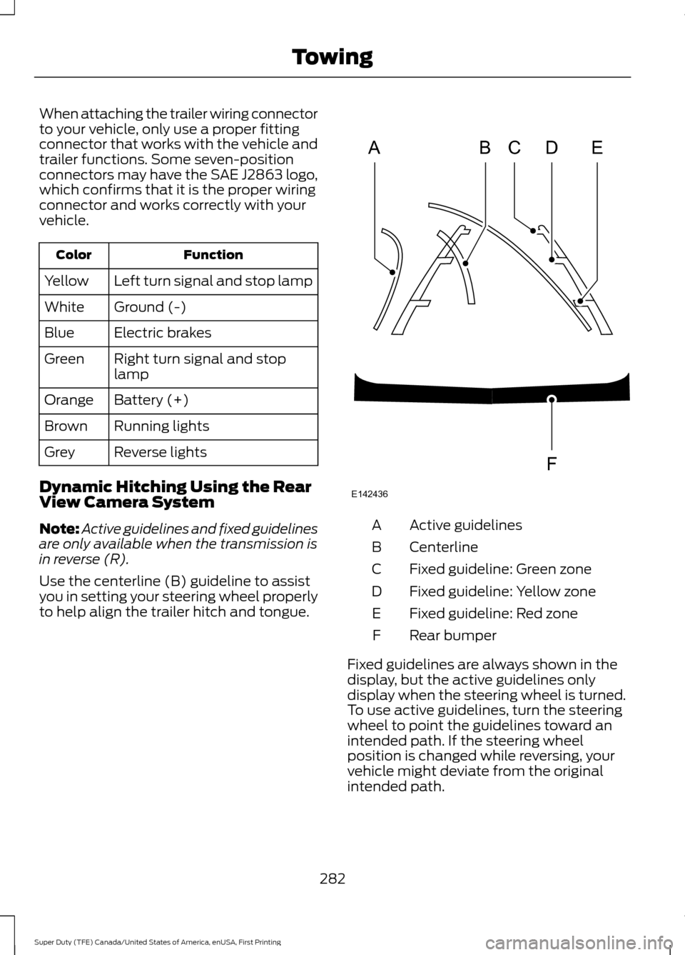
Dynamic Hitching Using the Rear
View Camera System
Note: Active guidelines and fixed guidelines
are only available when the transmission is
in reverse (R).
Use the centerline (B) guideline to assist
you in setting your steering wheel properly
to help align the trailer hitch and tongue. Active guidelines
A
Centerline
B
Fixed guideline: Green zone
C
Fixed guideline: Yellow zone
D
Fixed guideline: Red zone
E
Rear bumper
F
Fixed guidelines are always shown in the
display, but the active guidelines only
display when the steering wheel is turned.
To use active guidelines, turn the steering
wheel to point the guidelines toward an
intended path. If the steering wheel
position is changed while reversing, your
vehicle might deviate from the original
intended path.
282
Super Duty (TFE) Canada/United States of America, enUSA, First Printing TowingABCD
F
E
E142436
Page 288 of 636
Integrated Trailer Brake Controller
(If Equipped)
WARNINGS
The anti-lock brake system does not
control the trailer brakes.
Use the integrated trailer brake
controller to properly adjust the
trailer brakes and check all
connections before towing a trailer. Failure
to follow this instruction could result in the
loss of control of your vehicle, personal
injury or death. Note:
The integrated Ford brake controller
is compatible with trailers equipped with
electric-actuated drum brakes and
electric-over hydraulic brake systems.
Note: The integrated Ford brake controller
does not control hydraulic surge-style
brakes. When used properly, the trailer brake
controller assists in smooth and effective
trailer braking by powering the trailer
’s
electric or electric-over-hydraulic brakes
with a proportional output based on the
towing vehicle ’s brake pressure.
You can adjust the amount of initial trailer
brake output by selecting one of three
settings through the message center. Ford has tested the trailer brake controller
to be compatible with several major
brands of electric-over-hydraulic trailer
brakes. Contact an authorized dealer for
information on which brands you can use.
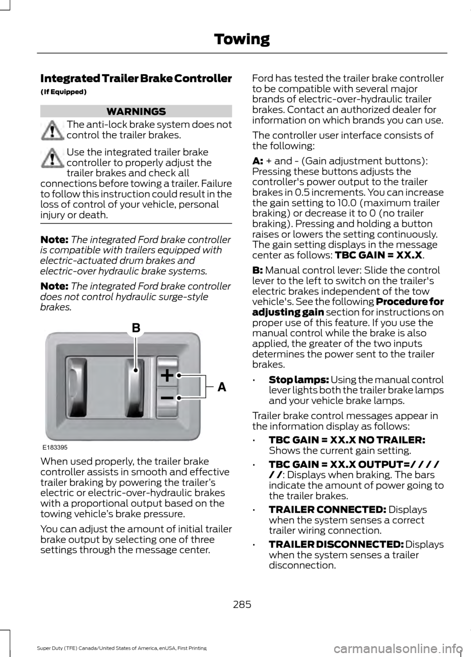
The controller user interface consists of
the following:
A: + and - (Gain adjustment buttons):
Pressing these buttons adjusts the
controller's power output to the trailer
brakes in 0.5 increments. You can increase
the gain setting to 10.0 (maximum trailer
braking) or decrease it to 0 (no trailer
braking). Pressing and holding a button
raises or lowers the setting continuously.
The gain setting displays in the message
center as follows:
TBC GAIN = XX.X.
B:
Manual control lever: Slide the control
lever to the left to switch on the trailer's
electric brakes independent of the tow
vehicle's. See the following Procedure for
adjusting gain section for instructions on
proper use of this feature. If you use the
manual control while the brake is also
applied, the greater of the two inputs
determines the power sent to the trailer
brakes.
• Stop lamps: Using the manual control
lever lights both the trailer brake lamps
and your vehicle brake lamps.
Trailer brake control messages appear in
the information display as follows:
• TBC GAIN = XX.X NO TRAILER:
Shows the current gain setting.
• TBC GAIN = XX.X OUTPUT=/ / / /
/ /
: Displays when braking. The bars
indicate the amount of power going to
the trailer brakes.
• TRAILER CONNECTED:
Displays
when the system senses a correct
trailer wiring connection.
• TRAILER DISCONNECTED: Displays
when the system senses a trailer
disconnection.
285
Super Duty (TFE) Canada/United States of America, enUSA, First Printing TowingE183395
Page 289 of 636
Procedure for Setting Trailer Brake
Controller Effort
Choose either the electric option for trailers
with electromagnetic drum brakes, or the
electric over hydraulic option for trailers
with these brake systems.
Trailer Brake Effort Setting
The trailer brake controller allows the user
to customize how aggressively the trailer
brakes engage. The default value is the low
setting and is the recommended setting
for most trailers. If your trailer's brakes
require more initial voltage, or if you prefer
more aggressive trailer braking, then select
either the medium or the high setting.
Procedure for Setting Trailer Brake
Controller Mode
Choose the low, medium or high setting
for the required initial trailer brake output.
Procedure for Adjusting Gain
Note:
Only perform this procedure in a
traffic-free environment at speeds of
approximately 20-25 mph (30-40 km/h).
The gain setting adjusts the trailer brake
controller for the specific towing condition.
You should change the setting as towing
conditions change. Changes to towing
conditions include trailer load, vehicle load,
road conditions and weather.
The gain should be set to provide the
maximum trailer braking assistance while
making sure the trailer wheels do not lock
when using the brakes. Locked trailer
wheels may lead to trailer instability.
1. Make sure the trailer brakes are in good
working condition, functioning normally
and properly adjusted. See your trailer
dealer if necessary.
2. Hook up the trailer and make the electrical connections according to the
trailer manufacturer's instructions. 3. When you plug in a trailer with electric
or electric-over-hydraulic brakes, a
confirmation message appears in the
information display.
4. Use the gain adjustment (+ and -) buttons to increase or decrease the
gain setting to the desired starting
point. A gain setting of 6.0 is a good
starting point for heavier loads.
5. In a traffic-free environment, tow the trailer on a dry, level surface at a speed
of 20-25 mph (30-40 km/h) and
squeeze the manual control lever
completely.
6. If the trailer wheels lock up, indicated by squealing tires, reduce the gain
setting. If the trailer wheels turn freely,
increase the gain setting. Repeat Steps
5 and 6 until the gain setting is at a
point just below trailer wheel lock-up.
If towing a heavier trailer, trailer wheel
lock-up may not be attainable even
with the maximum gain setting of 10.
Information Display Warning Messages
Note: An authorized dealer can diagnose
the trailer brake controller to determine
exactly which trailer fault has occurred.
However, your Ford warranty does not cover
this diagnosis if the fault is with the trailer.
TRAILER BRAKE MODULE FAULT
Displays in response to faults sensed by
the trailer brake controller, accompanied
by a single tone. If this message appears,
contact an authorized dealer as soon as
possible for diagnosis and repair. The
controller may still function, but with
degraded performance.
WIRING FAULT ON TRAILER
Displays when there is a short circuit on
the electric brake output wire.
286
Super Duty (TFE) Canada/United States of America, enUSA, First Printing Towing
Page 290 of 636
If this message displays, with no trailer
connected, the problem is with your vehicle
wiring or trailer brake controller. Contact
an authorized dealer.
If the message only displays with a trailer
connected, the problem is with the trailer
wiring. Consult your trailer dealer for
assistance. This can be a short to ground
(such as a chaffed wire), short to voltage
(such as a pulled pin on trailer emergency
breakaway battery) or the trailer brakes
may be drawing too much current.
Points to Remember
Note:
Do not attempt removal of the trailer
brake controller without consulting the
Workshop Manual. Damage to the unit may
result.
• Adjust gain setting before using the
trailer brake controller.
• Adjust gain setting, using the procedure
above, whenever road, weather, trailer
or vehicle loading conditions change
from when the gain was initially set.
• Only use the manual control lever for
proper adjustment of the gain during
trailer setup. Misuse, such as
application during trailer sway, could
cause instability of trailer or tow
vehicle.
• Avoid towing in adverse weather
conditions. The trailer brake controller
does not provide anti-lock control of
the trailer wheels. Trailer wheels can
lock up on slippery surfaces, resulting
in reduced stability of trailer and tow
vehicle.
• The trailer brake controller is equipped
with a feature that reduces output at
vehicle speeds below 11 mph (18 km/h)
so trailer and vehicle braking is not jerky
or harsh. This feature is only active
when applying the brakes using your
vehicle's brake pedal, not the
controller. •
The controller interacts with the brake
control system and powertrain control
system of your vehicle to provide the
best performance on different road
conditions.
• Your vehicle's brake system and the
trailer brake system work
independently of each other. Changing
the gain setting on the controller does
not affect the operation of your
vehicle's brakes.
• When you switch the engine off, the
controller output is disabled and the
display and module shut down.
Trailer Lamps WARNING
Never connect any trailer lamp wiring
to the vehicle's tail lamp wiring; this
may damage the electrical system
resulting in fire. Contact your authorized
dealer as soon as possible for assistance
in proper trailer tow wiring installation.
Additional electrical equipment may be
required. Trailer lamps are required on most towed
vehicles. Make sure all running lights, brake
lights, turn signals and hazard lights are
working.
Before Towing a Trailer
Practice turning, stopping and backing up
to get the feel of your vehicle-trailer
combination before starting on a trip.
When turning, make wider turns so the
trailer wheels clear curbs and other
obstacles.
287
Super Duty (TFE) Canada/United States of America, enUSA, First Printing Towing
Page 320 of 636
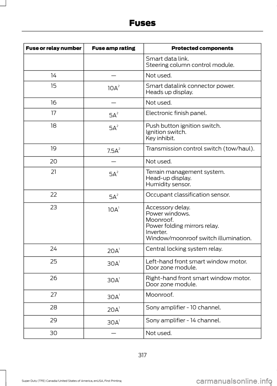
Protected components
Fuse amp rating
Fuse or relay number
Smart data link.
Steering column control module.
Not used.
—
14
Smart datalink connector power.
10A 2
15
Heads up display.
Not used.
—
16
Electronic finish panel.
5A 2
17
Push button ignition switch.
5A 2
18
Ignition switch.
Key inhibit.
Transmission control switch (tow/haul).
7.5A 2
19
Not used.
—
20
Terrain management system.
5A 2
21
Head-up display.
Humidity sensor.
Occupant classification sensor.
5A 2
22
Accessory delay.
10A 1
23
Power windows.
Moonroof.
Power folding mirrors relay.
Inverter.
Window/moonroof switch illumination.
Central locking system relay.
20A 1
24
Left-hand front smart window motor.
30A 1
25
Door zone module.
Right-hand front smart window motor.
30A 1
26
Door zone module.
Moonroof.
30A 1
27
Sony amplifier - 10 channel.
20A 1
28
Sony amplifier - 14 channel.
30A 1
29
Not used.
—
30
317
Super Duty (TFE) Canada/United States of America, enUSA, First Printing Fuses
Page 321 of 636
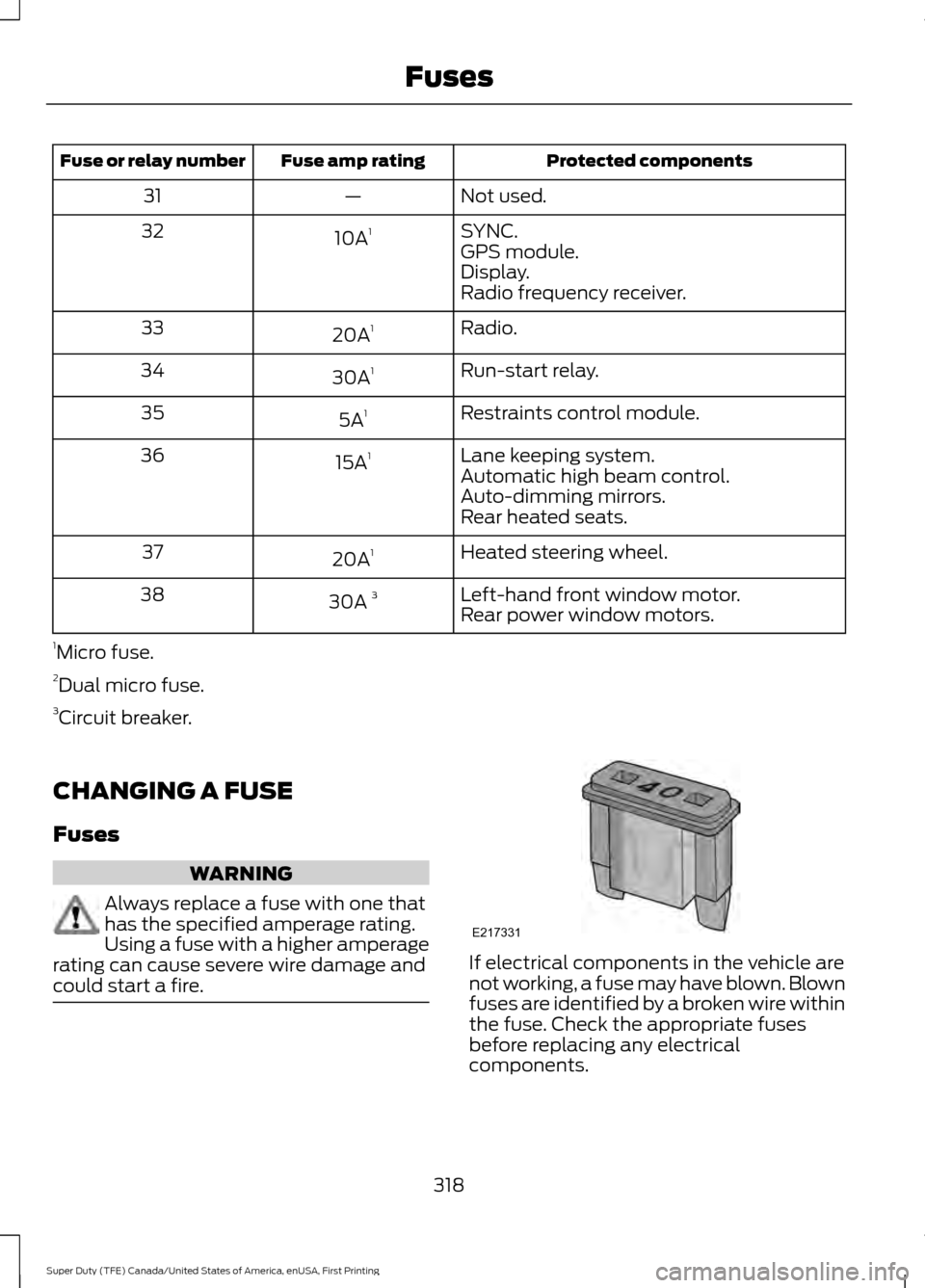
Protected components
Fuse amp rating
Fuse or relay number
Not used.
—
31
SYNC.
10A 1
32
GPS module.
Display.
Radio frequency receiver.
Radio.
20A 1
33
Run-start relay.
30A 1
34
Restraints control module.
5A 1
35
Lane keeping system.
15A 1
36
Automatic high beam control.
Auto-dimming mirrors.
Rear heated seats.
Heated steering wheel.
20A 1
37
Left-hand front window motor.
30A 3
38
Rear power window motors.
1 Micro fuse.
2 Dual micro fuse.
3 Circuit breaker.
CHANGING A FUSE
Fuses WARNING
Always replace a fuse with one that
has the specified amperage rating.
Using a fuse with a higher amperage
rating can cause severe wire damage and
could start a fire. If electrical components in the vehicle are
not working, a fuse may have blown. Blown
fuses are identified by a broken wire within
the fuse. Check the appropriate fuses
before replacing any electrical
components.
318
Super Duty (TFE) Canada/United States of America, enUSA, First Printing FusesE217331
Page 330 of 636
WARNINGS
Continuous contact with used motor
oil has caused cancer in laboratory
mice. Protect your skin by washing
with soap and water. If your vehicle is equipped with a diesel
engine, an Intelligent Oil Life Monitor™
calculates the proper oil change service
interval. When the information display
indicates: OIL CHANGE REQUIRED, change
the engine oil and oil filter. See
Information Displays (page 111).
The engine oil filter protects your engine
by filtering harmful, abrasive or sludge
particles and particles significantly smaller
than most available will-fit filters. See
Motorcraft Parts
(page 414).
1. Unscrew the oil filter and oil pan drain plug and wait for the oil to drain.
2. Replace the filter.
3. Reinstall the oil pan drain plug.
4. Refill the engine with new oil. See Capacities and Specifications (page
428
).
5. For diesel engines, you need to reset the Intelligent Oil Life Monitor™. See
Information Displays
(page 111).
Engine lubrication for severe
service operation
The following conditions define severe
operation for which engine operation with
SAE 5W-40 API CJ-4 is recommended. Oil
and oil filter change intervals will be
determined by the Intelligent Oil Life
Monitor™ as noted previously.
• Frequent or extended idling (over 10
minutes per hour of normal driving).
• Low-speed operation/stationary use.
• If vehicle is operated in sustained
ambient temperatures below
-9°F
(-23°C) or above 100°F (38°C). •
Frequent low-speed operation,
consistent heavy traffic less than
25 mph (40 km/h)
.
• Operating in severe dust conditions.
• Operating the vehicle off road.
• Towing a trailer over
1,000 mi
(1,600 km).
• Sustained, high-speed driving at Gross
Vehicle Weight Rating (maximum
loaded weight for vehicle operation).
• Use of fuels with sulfur content other
than ultra-low sulfur diesel (ULSD).
• Use of high-sulfur diesel fuel.
CHANGING THE COALESCER
FILTER ELEMENT WARNING
Do not dispose of engine oil or oil
filters in the household refuse or the
public sewage system. Use an
authorized waste disposal facility. Do not clean or recondition the filter
element.
We recommend that you demand the use
of genuine Ford and Motorcraft® parts
whenever your vehicle requires scheduled
maintenance or repair. Use the correct
specification filter element. See
Motorcraft Parts
(page 415).
Note: Operating your vehicle without a filter
element or with an unapproved filter
element may result in damage to the turbo
charger or exchanger and could lead to
engine damage that may not be covered by
the vehicle Warranty.
327
Super Duty (TFE) Canada/United States of America, enUSA, First Printing Maintenance