2017 FORD SUPER DUTY length
[x] Cancel search: lengthPage 39 of 636
The seatbelt pretensioners at the front
seating positions are designed to tighten
the seatbelts when activated. In frontal
and near-frontal crashes, the seatbelt
pretensioners may be activated alone or,
if the crash is of sufficient severity, together
with the front airbags. In side crashes and
rollovers, the seatbelt pretensioners
activate when the Safety Canopy is
activated.
FASTENING THE SEATBELTS
Standard belts shown, inflatable belts
similar
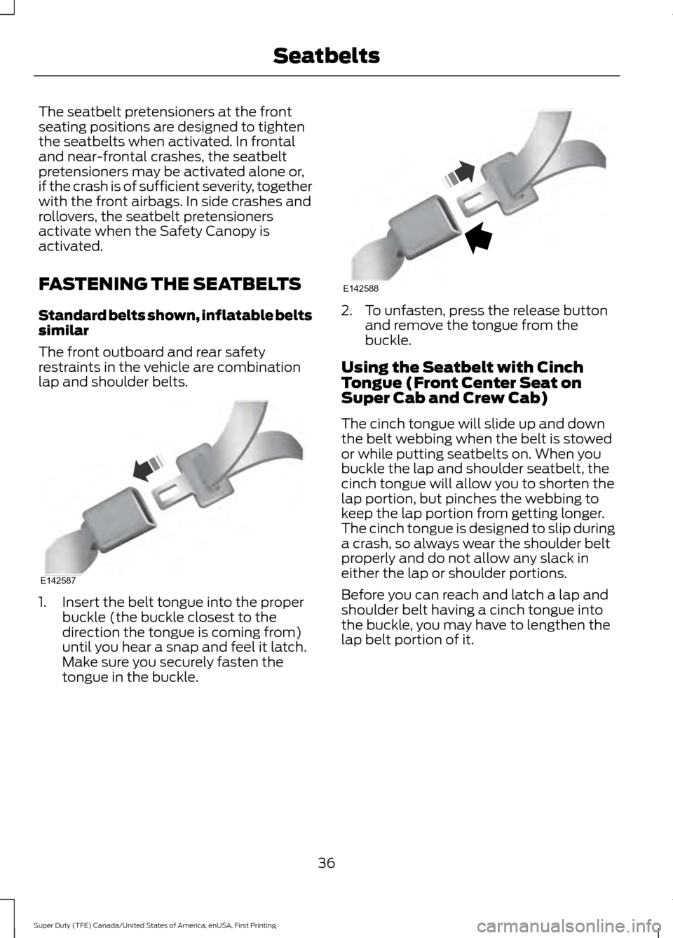
The front outboard and rear safety
restraints in the vehicle are combination
lap and shoulder belts.
1. Insert the belt tongue into the proper
buckle (the buckle closest to the
direction the tongue is coming from)
until you hear a snap and feel it latch.
Make sure you securely fasten the
tongue in the buckle. 2. To unfasten, press the release button
and remove the tongue from the
buckle.
Using the Seatbelt with Cinch
Tongue (Front Center Seat on
Super Cab and Crew Cab)
The cinch tongue will slide up and down
the belt webbing when the belt is stowed
or while putting seatbelts on. When you
buckle the lap and shoulder seatbelt, the
cinch tongue will allow you to shorten the
lap portion, but pinches the webbing to
keep the lap portion from getting longer.
The cinch tongue is designed to slip during
a crash, so always wear the shoulder belt
properly and do not allow any slack in
either the lap or shoulder portions.
Before you can reach and latch a lap and
shoulder belt having a cinch tongue into
the buckle, you may have to lengthen the
lap belt portion of it.
36
Super Duty (TFE) Canada/United States of America, enUSA, First Printing SeatbeltsE142587 E142588
Page 40 of 636
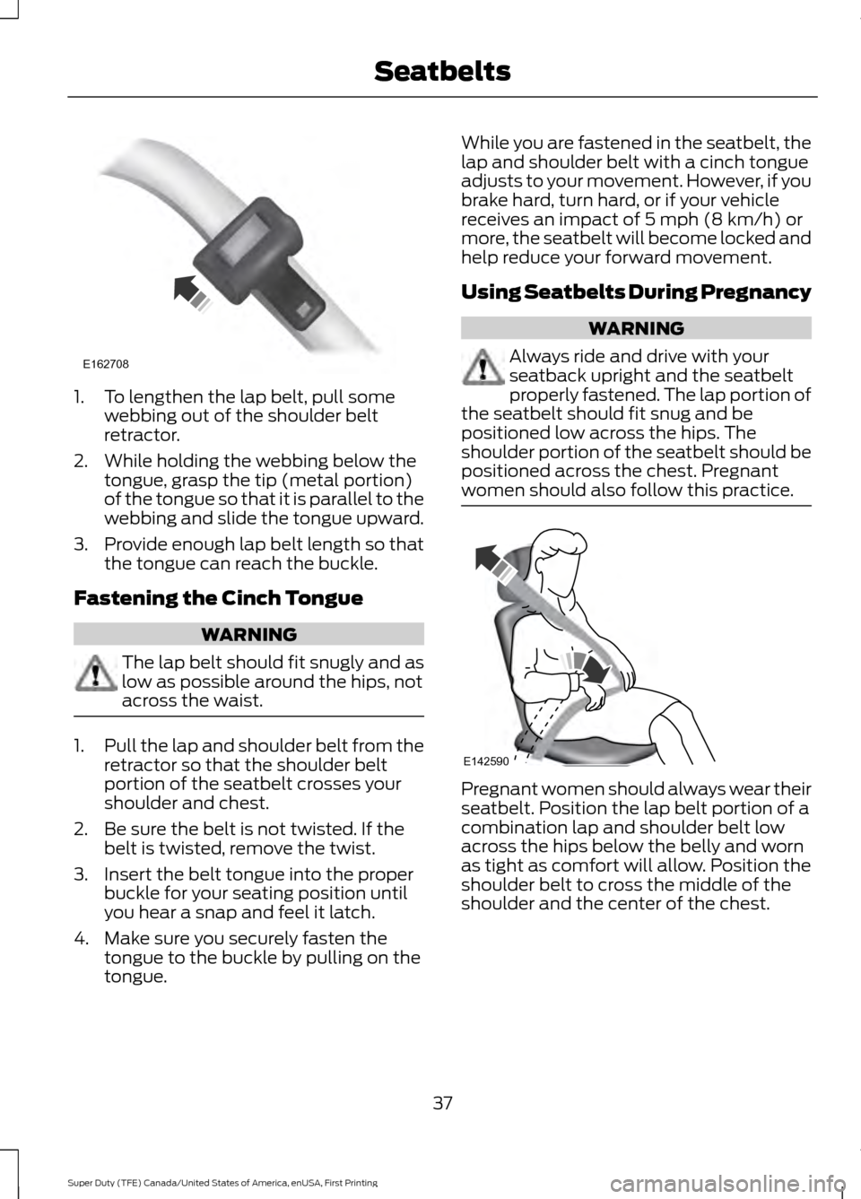
1. To lengthen the lap belt, pull some
webbing out of the shoulder belt
retractor.
2. While holding the webbing below the tongue, grasp the tip (metal portion)
of the tongue so that it is parallel to the
webbing and slide the tongue upward.
3. Provide enough lap belt length so that
the tongue can reach the buckle.
Fastening the Cinch Tongue WARNING
The lap belt should fit snugly and as
low as possible around the hips, not
across the waist.
1.
Pull the lap and shoulder belt from the
retractor so that the shoulder belt
portion of the seatbelt crosses your
shoulder and chest.
2. Be sure the belt is not twisted. If the belt is twisted, remove the twist.
3. Insert the belt tongue into the proper buckle for your seating position until
you hear a snap and feel it latch.
4. Make sure you securely fasten the tongue to the buckle by pulling on the
tongue. While you are fastened in the seatbelt, the
lap and shoulder belt with a cinch tongue
adjusts to your movement. However, if you
brake hard, turn hard, or if your vehicle
receives an impact of 5 mph (8 km/h) or
more, the seatbelt will become locked and
help reduce your forward movement.
Using Seatbelts During Pregnancy
WARNING
Always ride and drive with your
seatback upright and the seatbelt
properly fastened. The lap portion of
the seatbelt should fit snug and be
positioned low across the hips. The
shoulder portion of the seatbelt should be
positioned across the chest. Pregnant
women should also follow this practice. Pregnant women should always wear their
seatbelt. Position the lap belt portion of a
combination lap and shoulder belt low
across the hips below the belly and worn
as tight as comfort will allow. Position the
shoulder belt to cross the middle of the
shoulder and the center of the chest.
37
Super Duty (TFE) Canada/United States of America, enUSA, First Printing SeatbeltsE162708 E142590
Page 41 of 636
Seatbelt Locking Modes
WARNINGS
After any vehicle crash, the seatbelt
system at all passenger seating
positions must be checked by an
authorized dealer to verify that the
automatic locking retractor feature for
child seats is still functioning properly. In
addition, all seatbelts should be checked
for proper function. The belt and retractor must be
replaced if the seatbelt assembly
automatic locking retractor feature
or any other seatbelt function is not
operating properly when checked by an
authorized dealer. Failure to replace the
belt and retractor assembly could increase
the risk of injury in crashes. All safety restraints in the vehicle are
combination lap and shoulder belts. The
driver seatbelt has the first type of locking
mode, and the front outboard passenger
and rear seat seatbelts have both types of
locking modes described as follows:
Vehicle Sensitive Mode
This is the normal retractor mode, which
allows free shoulder belt length
adjustment to your movements and
locking in response to vehicle movement.
For example, if the driver brakes suddenly,
turns a corner sharply, or the vehicle
receives an impact of about 5 mph
(8 km/h) or more, the combination
seatbelts will lock to help reduce forward
movement of the driver and passengers.
In addition, the retractor is designed to lock
if the webbing is pulled out too quickly. If
this occurs, let the belt retract slightly and
pull webbing out again in a slow and
controlled manner. Automatic Locking Mode
In this mode, the shoulder belt is
automatically pre-locked. The belt will still
retract to remove any slack in the shoulder
belt. The automatic locking mode is not
available on the driver seatbelt.
When to Use the Automatic Locking
Mode
Use this mode any time you install a child
safety seat in a front outboard passenger
seating position in a Regular Cab,
SuperCab, SuperCrew or any rear seating
position of a SuperCab or SuperCrew. The
optional front seat's center seatbelt has a
cinch mechanism. Children 12 years old
and under should be properly restrained in
a rear seat whenever possible. See
Child
Safety (page 17).
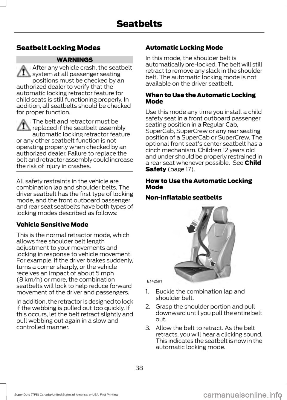
How to Use the Automatic Locking
Mode
Non-inflatable seatbelts 1. Buckle the combination lap and
shoulder belt.
2. Grasp the shoulder portion and pull downward until you pull the entire belt
out.
3. Allow the belt to retract. As the belt retracts, you will hear a clicking sound.
This indicates the seatbelt is now in the
automatic locking mode.
38
Super Duty (TFE) Canada/United States of America, enUSA, First Printing SeatbeltsE142591
Page 241 of 636
Auxiliary Camera (If Equipped)
Note: The auxiliary camera works with
trailers up to
50 ft (15 m) in length. Access the auxiliary camera view
by pressing the button on the
display screen when in reverse
(R).
The auxiliary camera system is a variant
of the rear view camera, comprised of a
camera with a built in amplifier. It is
designed to display a rear view image from
the back of a trailer while reversing. The
auxiliary camera is not meant as an
alternative to the rear view camera.
238
Super Duty (TFE) Canada/United States of America, enUSA, First Printing Parking AidsE233727
Page 255 of 636
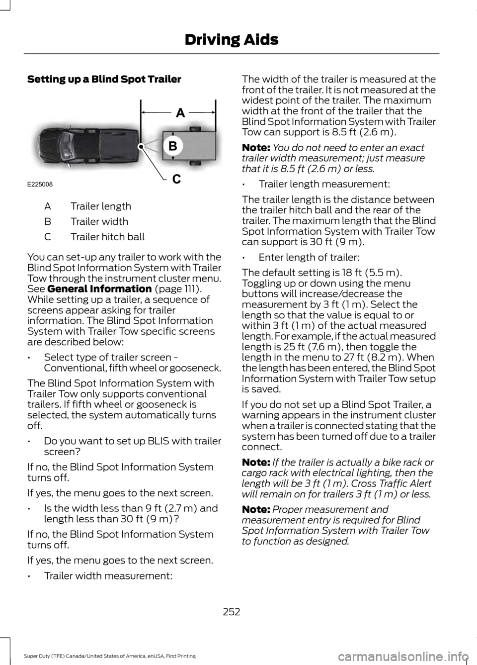
Setting up a Blind Spot Trailer
Trailer length
A
Trailer width
B
Trailer hitch ball
C
You can set-up any trailer to work with the
Blind Spot Information System with Trailer
Tow through the instrument cluster menu.
See General Information (page 111).
While setting up a trailer, a sequence of
screens appear asking for trailer
information. The Blind Spot Information
System with Trailer Tow specific screens
are described below:
• Select type of trailer screen -
Conventional, fifth wheel or gooseneck.
The Blind Spot Information System with
Trailer Tow only supports conventional
trailers. If fifth wheel or gooseneck is
selected, the system automatically turns
off.
• Do you want to set up BLIS with trailer
screen?
If no, the Blind Spot Information System
turns off.
If yes, the menu goes to the next screen.
• Is the width less than
9 ft (2.7 m) and
length less than 30 ft (9 m)?
If no, the Blind Spot Information System
turns off.
If yes, the menu goes to the next screen.
• Trailer width measurement: The width of the trailer is measured at the
front of the trailer. It is not measured at the
widest point of the trailer. The maximum
width at the front of the trailer that the
Blind Spot Information System with Trailer
Tow can support is
8.5 ft (2.6 m).
Note: You do not need to enter an exact
trailer width measurement; just measure
that it is
8.5 ft (2.6 m) or less.
• Trailer length measurement:
The trailer length is the distance between
the trailer hitch ball and the rear of the
trailer. The maximum length that the Blind
Spot Information System with Trailer Tow
can support is
30 ft (9 m).
• Enter length of trailer:
The default setting is
18 ft (5.5 m).
Toggling up or down using the menu
buttons will increase/decrease the
measurement by
3 ft (1 m). Select the
length so that the value is equal to or
within
3 ft (1 m) of the actual measured
length. For example, if the actual measured
length is
25 ft (7.6 m), then toggle the
length in the menu to 27 ft (8.2 m). When
the length has been entered, the Blind Spot
Information System with Trailer Tow setup
is saved.
If you do not set up a Blind Spot Trailer, a
warning appears in the instrument cluster
when a trailer is connected stating that the
system has been turned off due to a trailer
connect.
Note: If the trailer is actually a bike rack or
cargo rack with electrical lighting, then the
length will be
3 ft (1 m). Cross Traffic Alert
will remain on for trailers 3 ft (1 m) or less.
Note: Proper measurement and
measurement entry is required for Blind
Spot Information System with Trailer Tow
to function as designed.
252
Super Duty (TFE) Canada/United States of America, enUSA, First Printing Driving AidsE225008
Page 256 of 636
System Operation
If you select a trailer in the display screen
prior to connecting the trailer, the system
will load that configuration and the
information cluster displays a message
when the trailer is connected. A second
message appears stating Cross Traffic
Alert has been turned off; the Blind Spot
Information System with Trailer Tow still
functions normally when driving forward.
If no trailer has been set up and a trailer is
connected, the instrument cluster provides
a message indicating a trailer is connected
followed by a message asking to select a
trailer from the existing list of trailers or to
add a trailer. In order for the Blind Spot
Information System with Trailer Tow to
function, an existing trailer must be
selected or a new trailer must be added. If
the request is ignored or if you exit the
screen, a message appears prompting you
that the system has been turned off due
to a trailer connect. This message may not
appear until your vehicle speed reaches
22 mph (35 km/h).
The Blind Spot Information System with
Trailer Tow activates when driving forward
for that particular trailer set up. If the
ignition is cycled, the Blind Spot
Information System with Trailer Tow
continues to function using the last trailer
selected.
Trailer Considerations
The Blind Spot Information System with
Trailer Tow is designed to work with any
trailer whose front width is
8.5 ft (2.6 m)
or less and total length from the trailer
hitch ball to the rear of the trailer is
30 ft
(9 m) or less. Different trailers may cause
a slight change in performance as outlined
below. Large box trailers may cause false alerts
to trigger when driving next to buildings or
near parking cars. A false alert may also
occur while making a 90-degree turn.
Trailers that are
8.5 ft (2.6 m) wide at the
front and have a total length greater than
20 ft (6 m)
may have delayed alerts from
passing vehicles when the vehicle is
passing at high speed.
A box trailer whose front width is
8.5 ft
(2.6 m) may cause early alerts when you
are over taking a vehicle.
When towing a clam shell or V-Nose box
trailer with a front width of
8.5 ft (2.6 m),
delayed alerts on merging vehicles that are
traveling the same speed as your vehicle
may occur.
System Errors
If the system senses a problem with the
left or right sensor, the telltale illuminates
and a message appears in the display
screen. See
Information Messages
(page 128).
Switching the System Off and On
You can temporarily switch the Blind Spot
Information System off in the display
screen. See
General Information (page
111). When the Blind Spot Information
System switches off, you do not receive
alerts and the display screen shows a
system off message. The telltale in the
cluster also illuminates. When you switch
the Blind Spot Information System on or
off, the alert indicators flash twice.
Note: The Blind Spot Information System
remembers the last selected on or off
setting.
You can also have the Blind Spot
Information System switched off
permanently at an authorized dealer. Once
switched off permanently, the system can
only be switched back on at an authorized
dealer.
253
Super Duty (TFE) Canada/United States of America, enUSA, First Printing Driving Aids
Page 274 of 636
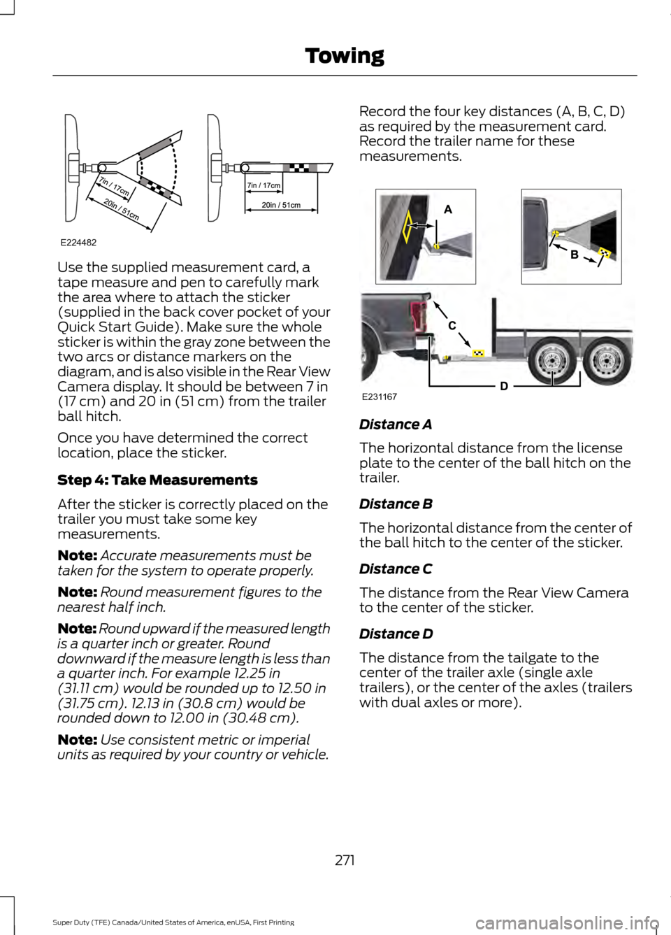
Use the supplied measurement card, a
tape measure and pen to carefully mark
the area where to attach the sticker
(supplied in the back cover pocket of your
Quick Start Guide). Make sure the whole
sticker is within the gray zone between the
two arcs or distance markers on the
diagram, and is also visible in the Rear View
Camera display. It should be between 7 in
(17 cm) and 20 in (51 cm) from the trailer
ball hitch.
Once you have determined the correct
location, place the sticker.
Step 4: Take Measurements
After the sticker is correctly placed on the
trailer you must take some key
measurements.
Note: Accurate measurements must be
taken for the system to operate properly.
Note: Round measurement figures to the
nearest half inch.
Note: Round upward if the measured length
is a quarter inch or greater. Round
downward if the measure length is less than
a quarter inch. For example
12.25 in
(31.11 cm) would be rounded up to 12.50 in
(31.75 cm). 12.13 in (30.8 cm) would be
rounded down to 12.00 in (30.48 cm).
Note: Use consistent metric or imperial
units as required by your country or vehicle. Record the four key distances (A, B, C, D)
as required by the measurement card.
Record the trailer name for these
measurements.
Distance A
The horizontal distance from the license
plate to the center of the ball hitch on the
trailer.
Distance B
The horizontal distance from the center of
the ball hitch to the center of the sticker.
Distance C
The distance from the Rear View Camera
to the center of the sticker.
Distance D
The distance from the tailgate to the
center of the trailer axle (single axle
trailers), or the center of the axles (trailers
with dual axles or more).
271
Super Duty (TFE) Canada/United States of America, enUSA, First Printing TowingE224482 E231167
Page 277 of 636
Accurate measurements are critical to
correct system function. If you need to
check measurements entered or change
them you can access them through the
trailer menus in the information display.
Choose the option to change the sticker
from the change trailer settings menu. It is
not necessary to remove the sticker if you
are just reviewing or changing
measurements.
The following menu warnings or difficulties
may occur during setup. Tips to resolve
them are listed below.
Measurement A has reached maximum or
minimum value:
•
The system is designed to work with
drawbars that have a license plate to
hitch ball center measurement of 9 in
(229 mm) to 16 in (406 mm) when
installed. Do not attempt to use
drawbars that have a length outside
this range as the system performance
will be degraded and could cause
improper system function.
• Make sure that the measurement being
made is the horizontal distance only
from license plate and the hitch ball
center. A straight line distance that
includes any vertical rise or drop will
increase the measurement and make
it inaccurate. Inaccurate
measurements will degrade system
performance and could cause improper
system function. See step 4 of the
setup instruction to review
measurement instructions. Measurement B has reached maximum or
minimum value:
•
Make sure that the sticker placement
instruction in step 3 of the setup has
been followed. Stickers placed outside
the allowed zone will adversely affect
the system performance and could
cause improper feature function.
• Make sure that the measurement being
made is the horizontal distance only
from center of sticker to the hitch ball
center. A straight line distance that
includes any vertical rise or drop will
increase the measurement and cause
an inaccurate value to be entered into
the system. See step 4 of the setup for
additional measurement instructions.
Measurement C has reached maximum or
minimum value:
• Make sure that the sticker placement
instructions in step 3 of the setup have
been followed. Stickers placed outside
the allowed zone will adversely affect
the system performance and could
cause improper feature function. If you
have met all the criteria for sticker
placement and you see this message
this sticker is either too far below or too
close to the camera to properly
recognize the sticker. In order for the
system to operate correctly the sticker
height must be lowered if you receive
the minimum warning or the sticker
height must be raised if you receive the
maximum warning.
•Only one sticker can be placed on
the trailer for correct system
function. The previous sticker must
be removed or covered so only one
sticker is visible to the camera.
• Measurement B and C must be
measured again if a new sticker is
placed on the trailer.
274
Super Duty (TFE) Canada/United States of America, enUSA, First Printing Towing