2017 FIAT TIPO 5DOORS STATION WAGON coolant
[x] Cancel search: coolantPage 34 of 264

1 - passenger compartment
temperature adjustment knob; the set
temperature is shown on the display;
2 - MAX A/C function on button;
3 - climate control compressor on/off
button;
4 - button for activating the MAX DEF
function (fast front window
defrosting/demisting);
5 - climate control system on/off
button;
6 - fan speed adjustment knob; the set
speed is shown on the display;
7 - air distribution selection buttons;
8 - heated rear window on/off button;
9 - internal air recirculation on/off
button;
10 - AUTO function activation button
(automatic operation).
Air distribution selection
By pressing the buttons//,it
is possible to set one of the 5 possible
air distributions manually:
Air flow to the windscreen and front
side window vents to
demist/defrost them.
Air flow at central and side
dashboard vents to ventilate the
chest and the face during the hot
season.
Air flow to the front and rear
footwell vents. This air distribution
setting heats the passenger
compartment most quickly, giving a
prompt sensation of warmth.
+Air flow distributed between
footwell vents (hotter air) and
central and side dashboard
vents (cooler air). This air
distribution setting is useful in
spring and autumn on sunny
days.
+Air flow distributed between
footwell vents and windscreen
and front side vents. This
distribution setting allows the
passenger compartment to be
warmed up efficiently and
prevents the windows from
misting up.
In AUTO mode, the climate control
system automatically manages air
distribution (the LEDs on buttons 7 are
off). When set manually, the air
distribution is indicated by the LEDs on
the selected buttons switching on.
In combined function mode the relevant
function is enabled simultaneously with
those already set by pressing the
corresponding button. If a button
whose function is already active is
pressed, the operation is cancelled and
the corresponding LED switches off. Torestore automatic control of the air
distribution after a manual selection,
press the AUTO button.
Start&Stop(where provided)
The automatic climate control system
manages the Start&Stop system
(engine off when vehicle speed is equal
to 0 km/h) to ensure adequate comfort
inside the vehicle.
When the Start&Stop system is on
(engine off and vehicle at a standstill),
the automatic recirculation
management is turned off always taking
air in from outside, to reduce the
probability of the windows misting up
(as the compressor is off).
IMPORTANT
2)The system uses a coolant that is
compatible with the laws in force in
countries where the vehicle is sold, R134a
or R1234yf. In case of a recharge
operation, only use the gas indicated on
the label placed in the engine
compartment. The use of other coolants
affects the efficiency and condition of the
system. The lubricant used for the
compressor is also strictly linked to the type
of cooling gas, please refer to a Fiat
Dealership.
32
KNOWING YOUR CAR
Page 47 of 264

LPG TANK
The car has a pressurised tank for
storing LPG in a liquid state. It is
toroidal and is located in the spare
wheel compartment with suitable
protection.
LPG tank certification
The LPG tank is certified in accordance
with the regulations in force.
In Italy, the tank has a life of 10 years
starting from the car registration date. If
the vehicle has been registered in a
country other than Italy, the duration
and the testing/inspection procedures
of the LPG tank can vary depending on
the national provisions in force in that
country. In all case, when the time limit
for your country has expired, go to a
Fiat Dealer to have the tank replaced.
SOLENOID VALVES AND
SAFETY DEVICES
The system has a solenoid valve
located on the pressure reduction unit
and a solenoid valve fitted inside the
multivalve stack on the tank.
The main function of these solenoid
valves is to interrupt/allow the flow of
LPG to the supply circuit.
The solenoid valves are open when:
a request to run on LPG has been
made;
the optimum engine running
conditions are satisfied (engine coolant
temperature, minimum revs level) for
running on LPG;
there is enough LPG in the tank for
operation.
The multivalve stack fitted on the tank
includes:
a valve that automatically stops the
supply of LPG when the maximum
permitted filling level is reached (80% of
the total tank capacity);
a flow limiter which, if a piping is
broken, prevents the complete and
sudden escape of LPG;
a check valve preventing LPG
back-flow to the filler;
a safety solenoid valve on the LPG
supply line for enabling or preventing
the flow of gas towards the pressure
reducer;
a manual valve, positioned upstream
of the solenoid valve for bypassing the
LPG system for servicing operations;
a melting pad which, in the case of
overheating (temperature above
120°C), totally eliminates the danger of
excess pressure, releasing the LPG in
the tank to the outside as quickly as
possible in a controlled manner;
an analogue level gauge for LPG in
the tank.
PIPES
The piping for the LPG in a liquid state
(from the filler to the tank and from the
tank to the pressure regulator) is made
from copper coated in plastic.
The supply piping for the LPG in a
gaseous state (from the pressure
regulator to the LPG injectors) are made
from rubber.
REGULATION UNIT
The regulation unit (see the figure)
includes:
cut-out solenoid valve with gauze
filter;
pressure regulator.
The cut-out solenoid valveopens or
closes together with the solenoid valve
on the tank. It closes all LPG flow when
the engine is not running on gas. It also
acts as a safety device that prevents
73PLG00006
45
Page 53 of 264

CONTROL PANEL AND ON-BOARD INSTRUMENTS
RECONFIGURABLE MULTIFUNCTION DISPLAY
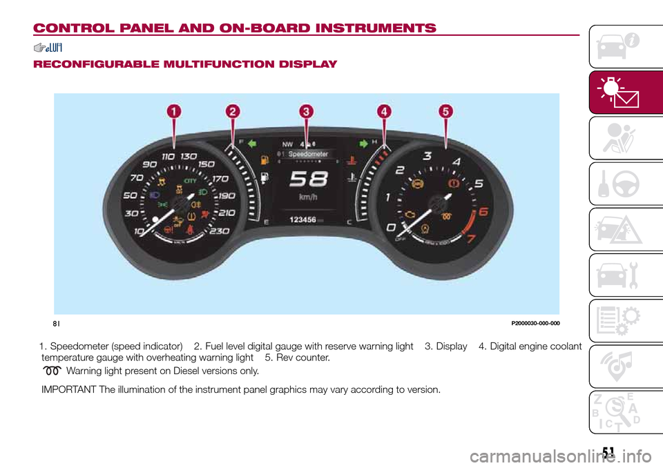
1. Speedometer (speed indicator) 2. Fuel level digital gauge with reserve warning light 3. Display 4. Digital engine coolant
temperature gauge with overheating warning light 5. Rev counter.
Warning light present on Diesel versions only.
IMPORTANT The illumination of the instrument panel graphics may vary according to version.
81P2000030-000-000
51
Page 55 of 264

MULTI-FUNCTIONAL RECONFIGURABLE DISPLAY — Right hand drive version
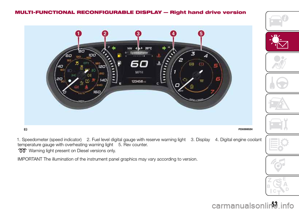
1. Speedometer (speed indicator) 2. Fuel level digital gauge with reserve warning light 3. Display 4. Digital engine coolant
temperature gauge with overheating warning light 5. Rev counter.
Warning light present on Diesel versions only.
IMPORTANT The illumination of the instrument panel graphics may vary according to version.
83PDX00002H
53
Page 63 of 264

Warning light What it means
ENGINE COOLANT TEMPERATURE TOO HIGH
The warning light on the display lights up when the engine has overheated.
In normal driving conditions: stop the car, switch off the engine and check that the coolant level in the
reservoir is not below the MIN mark. In this case, wait for the engine to cool down, then slowly and
carefully open the cap, top up with coolant and check that the level is between the MIN and MAX marks
on the reservoir itself. Also check visually for any fluid leaks. If, when restarting, the warning light on the
display switches on again, contact a Fiat Dealership;
If the vehicle is used under demanding conditions(e.g. in high-performance driving): slow down
and, if the warning light stays on, stop the vehicle. Stop for two or three minutes with the engine running
and slightly accelerated to facilitate better coolant circulation, then turn the engine off. Check that the
coolant level is correct as described above.
IMPORTANT Over demanding routes, it is advisable to keep the engine running and slightly accelerated
for a few minutes before turning it off.
AIRBAG FAILURE
If the warning light switches on constantly, this indicates a failure in the airbag system.
34) 35)
WARNING
34)If, when the ignition device is turned to MAR, thewarning light does not switch on or stays on whilst driving, a failure may have
occurred in the restraint systems. In this case the airbags or pretensioners may not be deployed in an impact or, in a lower number of cases,
they may be deployed accidentally. Before continuing, contact a Fiat Dealership immediately to have the system checked.
35)The failure of the
warning light is signalled by the lighting up of thesymbol on the instrument panel display (or, for versions where
provided, by the flashing of the generic failure warning light). In this case, the warning light may not indicate any faults with the restraint
systems. Before continuing, contact a Fiat Dealership immediately to have the system checked
61
Page 171 of 264

PERIODIC CHECKS
Every1,000km or before long trips
check and, if necessary, top up:
engine coolant level;
brake fluid level;
windscreen washer fluid level;
tyre inflation pressure and condition;
operation of lighting system
(headlights, direction indicators, hazard
warning lights, etc.);
operation of screen washing/wiping
system and positioning/wear of wiper
blades.
Every3,000km, check and top up if
required: engine oil level.
DEMANDING USE OF THE
CAR
If the vehicle is used mainly under one
of the following conditions:
dusty roads;
short, repeated journeys (less than
7-8 km) at sub-zero outside
temperatures;
engine often idling or driving long
distances at low speeds or long periods
of inactivity;
the following checks must be carried
out more often than indicated in the
Scheduled Servicing Plan:
check front disc brake pad condition
and wear;
check cleanliness of bonnet and
luggage compartment locks,cleanliness and lubrication of linkage;
visually inspect conditions of: engine,
gearbox, transmission, pipes and hoses
(exhaust/fuel system/brakes) and
rubber elements (gaiters/sleeves/
bushes, etc.);
check battery charge and battery
fluid level (electrolyte);
visually inspect conditions of the
accessory drive belts;
check and, if necessary, change
engine oil and replace oil filter;
check and, if necessary, replace
pollen filter;
check and, if necessary, replace air
cleaner.
169
Page 172 of 264

ENGINE COMPARTMENT
CHECKING LEVELS
152) 153)
64)
1.4 16V 95 HP version
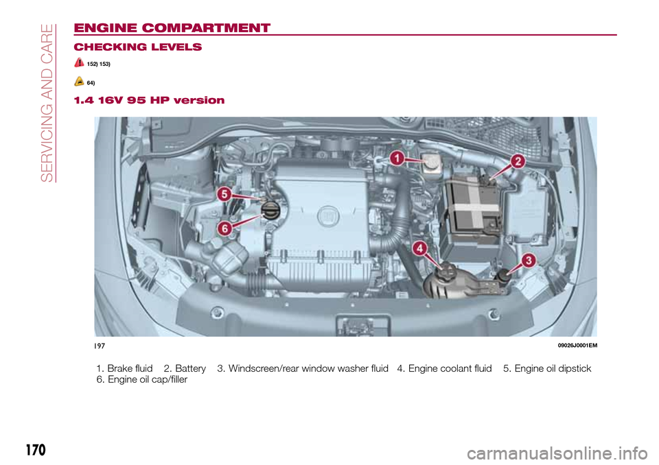
1. Brake fluid 2. Battery 3. Windscreen/rear window washer fluid 4. Engine coolant fluid 5. Engine oil dipstick
6. Engine oil cap/filler
19709026J0001EM
170
SERVICING AND CARE
Page 173 of 264

1.4 T-Jet 120 HP version
1. Brake fluid 2. Battery 3. Windscreen/rear window washer fluid 4. Engine coolant fluid 5. Engine oil dipstick
6. Engine
oil cap/filler
198P1030198-000-000
171