2017 FIAT TIPO 5DOORS STATION WAGON tyre pressure
[x] Cancel search: tyre pressurePage 57 of 264

to reset the displayed/selected
functions.
MAIN MENU
The Main menu comprises a series of
items which can be selected using the
control buttons to access the different
selection and setting options given in
the following paragraphs.
REMARKS
Some options have a submenu.
With theUconnect™ 5"or7" HD
system, some Menu items are shown
and managed on the display of the
latter and not on the instrument panel
display (refer to the dedicated
Multimedia chapter or to the
supplement available online).
MENU OPTIONS
The Menu includes the following items:
TRIP
GSI
VEHICLE INFO
DRIVER ASSIST
AUDIO (function available in versions
and markets where present)
PHONE (function available in versions
and markets where present)
NAVIGATION (function available in
versions and markets where present)
ALERTS
VEHICLE SETTINGSTrip
This menu item displays the information
on the "Trip computer" (for further
information, see the description of the
"Trip computer" paragraph in this
chapter).
The information shown on the display is
as follows:
Instant info: distance (km or miles),
instantaneous consumption (mpg,
l/100 km or km/l);
Trip A: distance A (km or miles), trip
time A (hours/minutes/seconds),
average consumption A (mpg, or
l/100 km or km/l), average speed A
(km/h or mph);
Trip B: distance B (km or miles),
average consumption B (mpg, or
l/100 km or km/l), trip time B
(hours/minutes/seconds), average
speed B (km/h or mph).
Speedometer: km or miles displayed.
By pressing theOKbutton with
speedometer display active, you can
change the measurement unit (km/h
or mph). On leaving this screen, the
measurement unit set will take effect.
GSI
This menu item makes it possible to
see the gear shift indicator provided by
the GSI (gear shift indicator) system on
the display.Vehicle info
This menu item displays the information
on the vehicle conditions.
Press the
orbutton to select the
items listed below.
Tyre pressure: information displayed on
the iTPMS (where provided) (for further
information, see the description in
paragraph "Auxiliary driving systems" in
the "Safety" chapter).
Engine oil temperature: engine oil
temperature displayed.
Change engine oil: indication for engine
oil change.
Battery voltage: display of the battery
voltage value (charge level).
Service (Scheduled servicing):Number
of kilometres (or miles) and days until
the next Scheduled Servicing operation.
WARNING
The “Scheduled Servicing Plan”
includes vehicle maintenance at fixed
intervals (refer to the "Maintenance and
care" chapter).
This is displayed automatically, with
ignition device at MAR, 2000 km before
servicing or, where provided, 30 days
before servicing. It is also displayed
each time the ignition device is turned
to MAR or, for some versions, every
200 km. Below this threshold servicing
indications are more frequent. The
55
Page 64 of 264

Warning light What it means
iTPMS
iTPMS failure/iTPMS temporarily deactivated
The warning light flashes for about 75 seconds and then stays on constantly (together with a message on
the display) to indicate that the system is temporarily deactivated or faulty. The system will go back to
normal operation when the operating conditions will allow it. If this is not the case, carry out the “Reset”
procedure after restoring the normal operating conditions.
If the malfunction warning persists, contact a Fiat Dealership as soon as possible.
Tyre pressure low
The warning light switches on constantly to indicate that the pressure of one or more tyres is lower than
the recommended value and/or that slow pressure loss is occurring. In these cases, optimal tyre duration
and fuel consumption may not be guaranteed. It is advisable to restore the correct pressure value (see the
"Wheels" paragraph in the "Technical specifications" section). Once the normal operating conditions of
the vehicle are restored, carry out the "Reset" procedure.
WARNING Do not continue driving with one or more flat tyres as the car handling may be compromised.
Stop the vehicle, avoiding sharp braking and steering.
ABS FAILURE
The warning light switches on to indicate an ABS fault. In this case the braking system maintains its
efficiency unaltered but without the advantage of the ABS system. Drive carefully and contact a Fiat
Dealership as soon as possible.
ESC SYSTEM
ESC system activation
Intervention by the system is indicated by the flashing of the warning light: it indicates that the car is in
critical stability and grip conditions.
ESC system failure
If the warning light does not switch off, or if it stays on with the engine running, a failure was found on the
ESC system. Contact a Fiat Dealership as soon as possible.
Hill Hold Control system failure
The warning light turns on to indicate a Hill Holder Control system failure. Contact a Fiat Dealership as soon
as possible.
62
KNOWING THE INSTRUMENT PANEL
Page 77 of 264

If these conditions occur, the warning
light
flashes on the instrument panel
and the system, intervening on the
brakes and engine power, limits the
possibility that the wheels are raised
from the ground. It is not possible to
avoid tendency to roll over if the
phenomenon is due to reasons such as
driving on high side gradients, collision
with objects or other vehicles.
58)
TSC (Trailer Sway
Control) SYSTEM
The system employs a series of sensors
located on the vehicle to identify
excessive swerving of the trailer and
take the necessary precautions to
eliminate it.
To counteract the effect of trailer sway,
the system can reduce the engine
power and intervene on the wheels
involved. The TSC system activates
automatically once excessive sway of
the trailer is detected.
System intervention
When the system is active, the
warning light flashes on the
instrument panel, the engine power is
reduced and braking can be felt on the
individual wheels, following the attempt
to eliminate the swerving of the trailer.
59) 60)
WARNING
36)When the ABS intervenes and you feel
the brake pedal pulsating, do not reduce
the pressure, but hold it down firmly and
confidently; in doing so you will brake in the
shortest distance possible, depending on
the current road conditions.
37)To obtain the maximum efficiency of
the braking system, a bedding-in period of
about 500 km is needed: during this period
it is better to avoid sharp, repeated and
prolonged braking.
38)If the ABS intervenes, this indicates
that the grip of the tyres on the road is
nearing its limit: you must slow down to a
speed compatible with the available grip.
39)The ABS cannot overrule the natural
laws of physics, and cannot increase the
grip available according to the condition of
the road.
40)The ABS cannot prevent accidents,
including those due to excessive speed on
corners, driving on low-grip surfaces or
aquaplaning.
41)The capability of the ABS must never
be tested irresponsibly and dangerously, in
such a way as to compromise personal
safety and the safety of others.
42)For the correct operation of the ABS,
the tyres must of necessity be the same
make and type on all wheels, in perfect
condition and, above all, of the prescribed
type and dimensions.
43)The ESC system cannot alter the
natural laws of physics, and cannot
increase grip, which depends on the
condition of the road.44)The ESC system cannot prevent
accidents, including those due to excessive
speed on corners, driving on low-grip
surfaces or aquaplaning.
45)The capability of the ESC system must
never be tested irresponsibly and
dangerously, in such a way as to
compromise personal safety and the safety
of others.
46)For the correct operation of the ESC
system, the tyres must necessarily be of
the same make and type on all wheels, in
perfect condition and, above all, of the
prescribed type and size.
47)ESC performance features must not
induce the driver to take unnecessary or
unwarranted risks. Your driving style must
always be suited to the road conditions,
visibility and traffic. The driver is, in any
case, responsible for safe driving.
48)For the correct operation of the TC
system, the tyres must of necessity be the
same make and type on all wheels, in
perfect condition and, above all, of the
prescribed type and dimensions.
49)TC performance features must not
induce the driver to take unnecessary or
unwarranted risks. Your driving style must
always be suited to the road conditions,
visibility and traffic. The driver is, in any
case, responsible for safe driving.
50)The TC system cannot overrule the
natural laws of physics, and cannot
increase the grip available according to the
condition of the road.
51)The TC system cannot prevent
accidents, including those due to excessive
speed on corners, driving on low-grip
surfaces or aquaplaning.
75
Page 82 of 264

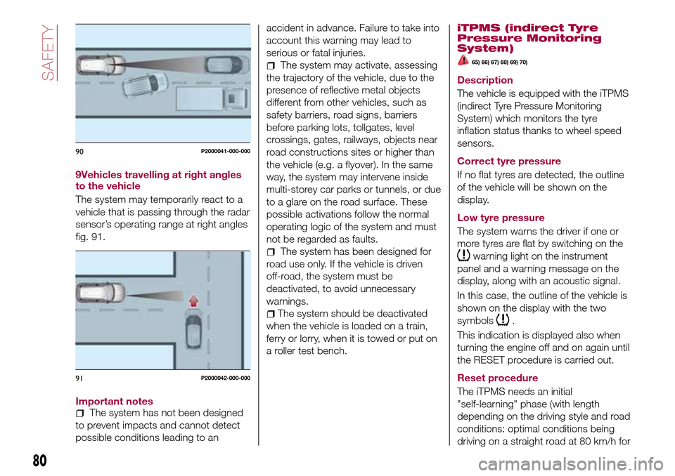
9Vehicles travelling at right angles
to the vehicle
The system may temporarily react to a
vehicle that is passing through the radar
sensor’s operating range at right angles
fig. 91.
Important notes
The system has not been designed
to prevent impacts and cannot detect
possible conditions leading to anaccident in advance. Failure to take into
account this warning may lead to
serious or fatal injuries.
The system may activate, assessing
the trajectory of the vehicle, due to the
presence of reflective metal objects
different from other vehicles, such as
safety barriers, road signs, barriers
before parking lots, tollgates, level
crossings, gates, railways, objects near
road constructions sites or higher than
the vehicle (e.g. a flyover). In the same
way, the system may intervene inside
multi-storey car parks or tunnels, or due
to a glare on the road surface. These
possible activations follow the normal
operating logic of the system and must
not be regarded as faults.
The system has been designed for
road use only. If the vehicle is driven
off-road, the system must be
deactivated, to avoid unnecessary
warnings.
The system should be deactivated
when the vehicle is loaded on a train,
ferry or lorry, when it is towed or put on
a roller test bench.
iTPMS (indirect Tyre
Pressure Monitoring
System)
65) 66) 67) 68) 69) 70)
Description
The vehicle is equipped with the iTPMS
(indirect Tyre Pressure Monitoring
System) which monitors the tyre
inflation status thanks to wheel speed
sensors.
Correct tyre pressure
If no flat tyres are detected, the outline
of the vehicle will be shown on the
display.
Low tyre pressure
The system warns the driver if one or
more tyres are flat by switching on the
warning light on the instrument
panel and a warning message on the
display, along with an acoustic signal.
In this case, the outline of the vehicle is
shown on the display with the two
symbols
.
This indication is displayed also when
turning the engine off and on again until
the RESET procedure is carried out.
Reset procedure
The iTPMS needs an initial
"self-learning" phase (with length
depending on the driving style and road
conditions: optimal conditions being
driving on a straight road at 80 km/h for
90P2000041-000-000
91P2000042-000-000
80
SAFETY
Page 83 of 264

at least 20 minutes) which starts when
the RESET procedure is carried out.
The RESET procedure must be carried
out:
each time tyre pressure is modified;
when even only one tyre is changed;
when tyres are rotated/inverted;
when the space-saver wheel is fitted.
Before carrying out the RESET
procedure, inflate the tyres to the rated
pressure values specified in the inflation
pressure table (see "Wheels" paragraph
in the "Technical specifications"
chapter).
If the RESET is not carried out, in all
above cases, the
warning light may
give false indications on one or more
tyres.
To carry out the RESET, with the vehicle
stationary and the engine on, hold
down the Reset button
located on
the left control panel fig. 92 for at least
2 seconds.
When the RESET procedure has been
carried out, and depending on the type
of instrument panel, either only a buzzer
will be heard or the message "Reset
saved" will appear together with the
buzzer to indicate that self-learning has
started.Operating conditions
The system is active for speeds above
15 km/h.
In a few situations such as sporty
driving, particular conditions of the road
surface (e.g. icy, snowy, unsurfaced
roads) the signalling may be delayed or
partial in detecting the contemporary
deflation of more than one tyre.
Under special conditions (e.g. vehicle
loaded asymmetrically on one side,
towing a trailer, damaged or worn tyre,
fitting the space-saver wheel, use of the
"Fix&Go Automatic" tyre repair kit, fitting
snow chains, fitting different tyres on
the axles) the system may provide false
indications or be temporarily
deactivated.
If the system is temporarily deactivated
the
warning light flashes for about
75 seconds and then is continuouslyon; at the same time, the display shows
a warning message.
This indication is displayed also after
the engine has been switched off and
then on again if the correct operating
conditions are not restored.
In the case of abnormal signals, it is
recommended to perform the RESET
procedure. If the signals reappear once
the RESET procedure has started,
check that the type of tyres used are
the same on all four wheels and that the
tyres are not damaged; if the
space-saver wheel is being used, refit
the wheel with a tire with normal
dimensions instead of the space-saver
wheel as soon as possible; if possible
remove the snow chains; make sure
that the load is distributed correctly and
repeat the RESET procedure, driving on
a clean and surfaced road. If the signals
persist, contact a Fiat Dealership.
WARNING
61)The system is an aid for the driver, who
must always pay full attention while driving.
The responsibility always rests with the
driver, who must take into account the
traffic conditions in order to drive in
complete safety. The driver must always
maintain a safe distance from the vehicle in
front.
9206056J0001EM
81
Page 84 of 264

62)If the driver depresses the brake pedal
fully or carries out a fast steering during
system operation, the automatic braking
function may stop (e.g. to allow a possible
manoeuvre to avoid the obstacle).
63)The system intervenes on vehicles
travelling in the same lane. People, animals
and things (e.g. pushchairs) are not taken
into consideration.
64)If the car must be placed on a roller
bench for maintenance interventions or if it
is washed in an automatic roller washing
tunnel with an obstacle in the front part
(e.g. another car, a wall or another
obstacle), the system may detect its
presence and activate. In this case the
system must be deactivated through the
settings of theUconnect™5"or7" HD
system.
65)If the iTMPS system signals a pressure
decrease on the tyres, it is recommended
to check the pressure on all four tyres.
66)The iTPMS does not relieve the driver
from the obligation to check the tyre
pressure every month; it is not even to be
considered a replacing system for
maintenance or a safety system.
67)Tyre pressure must be checked with
tyres cold. Should it become necessary for
whatever reason to check pressure with
warm tyres, do not reduce pressure even
though it is higher than the prescribed
value, but repeat the check when tyres are
cold
68)The iTPMS cannot indicate sudden tyre
pressure drops (e.g. if a tyre bursts). In this
case, stop the vehicle, braking with caution
and avoiding abrupt steering.
69)The system only warns that the tyre
pressure is low: it is not able to inflate
them.70)Insufficient tyre inflation increases fuel
consumption, reduces the tread duration
and may affect the capacity to drive safely.
IMPORTANT
27)The system may have limited or absent
operation due to weather conditions such
as: heavy rain, hail, thick fog, heavy snow.
28)The section of the bumper before the
sensor must not be covered with
adhesives, auxiliary headlights or any other
object.
29)System intervention might be
unexpected or delayed when other vehicles
transport loads projecting from the side,
above or from the rear, with respect to the
normal size of the vehicle.
30)Operation can be adversely affected by
any structural change made to the vehicle,
such as a modification to the front
geometry, tyre change, or a heavier load
than the standard load of the vehicle.
31)Incorrect repairs made on the front part
of the vehicle (e.g. bumper, chassis) may
alter the position of the radar sensor, and
adversely affect its operation. Go to a Fiat
Dealership for any operation of this type.
32)Do not tamper nor operate on the radar
sensor. In the event of a sensor failure,
contact a Fiat Dealership.
33)When towing a trailer (with modules
installed after purchasing the vehicle), a
vehicle or during loading manoeuvres on a
vehicle transporter (or in vehicle for
transport), the system must be deactivated
via theUconnect™5"or7" HDsystem.34)Do not wash with high-pressure jets in
the bumper lower area: in particular do not
operate on the system's electrical
connector.
35)Be careful in the case of repairs and
new paintings in the area around the
sensor (panel covering the sensor on the
left side of the bumper). In the event of a
frontal impact the sensor may automatically
deactivate and display a warning to indicate
that the sensor needs to be repaired. Even
without a malfunction warning, deactivate
the system operation if you think that the
position of the radar sensor has changed
(e.g. due to low-speed frontal impact as
during parking manoeuvres). In these
cases, go to a Fiat Dealership to have the
radar sensor realigned or replaced.
82
SAFETY
Page 125 of 264

44)The section of the bumper before the
sensor must not be covered with
adhesives, auxiliary headlights or any other
object.
45)Operation can be adversely affected by
any structural change made to the vehicle,
such as a modification to the front
geometry, tyre change, or a heavier load
than the standard load of the vehicle.
46)Incorrect repairs made on the front part
of the vehicle (e.g. bumper, chassis) may
alter the position of the radar sensor, and
adversely affect its operation. Go to a Fiat
Dealership for any operation of this type.
47)Do not tamper nor operate on the radar
sensor. In the event of a sensor failure,
contact a Fiat Dealership.
48)Do not wash with high-pressure jets in
the bumper lower area: in particular do not
operate on the system's electrical
connector.
49)Be careful in the case of repairs and
new paintings in the area around the
sensor (panel covering the sensor on the
left side of the bumper). In the event of a
frontal impact the sensor may automatically
deactivate and display a warning to indicate
that the sensor needs to be repaired. Even
without a malfunction warning, deactivate
the system operation if you think that the
position of the radar sensor has changed
(e.g. due to low-speed frontal impact as
during parking manoeuvres). In these
cases, go to a Fiat Dealership to have the
radar sensor realigned or replaced.PARKING SENSORS
(where provided)
SENSORS
123)
50) 51) 52)
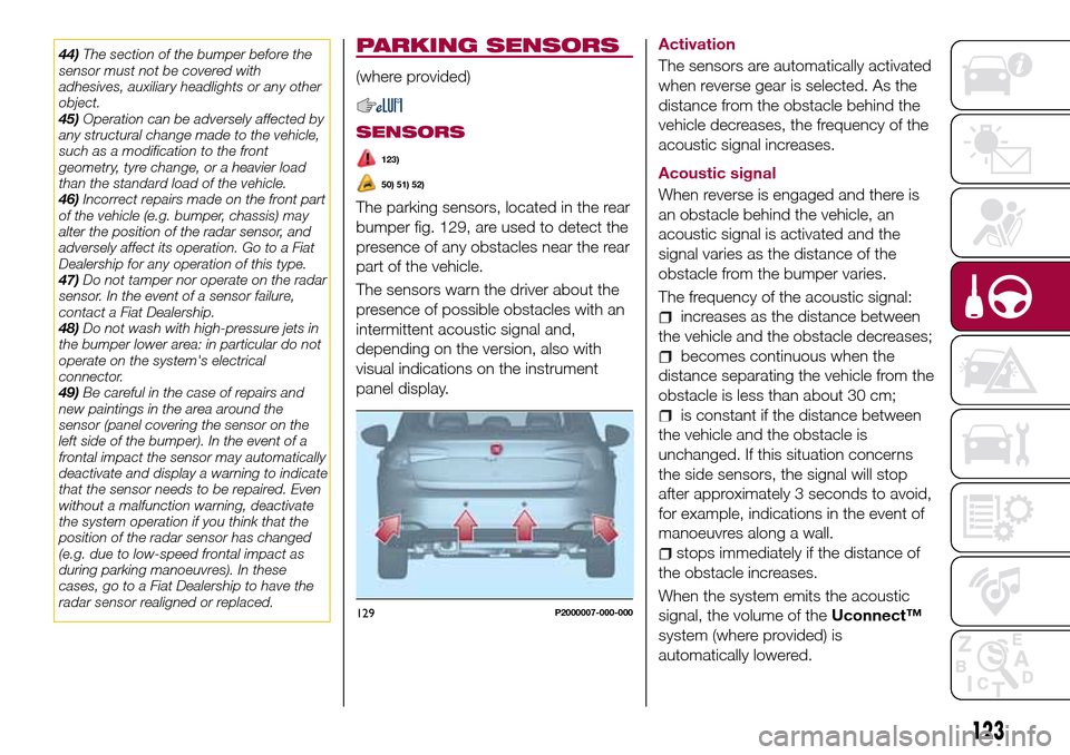
The parking sensors, located in the rear
bumper fig. 129, are used to detect the
presence of any obstacles near the rear
part of the vehicle.
The sensors warn the driver about the
presence of possible obstacles with an
intermittent acoustic signal and,
depending on the version, also with
visual indications on the instrument
panel display.Activation
The sensors are automatically activated
when reverse gear is selected. As the
distance from the obstacle behind the
vehicle decreases, the frequency of the
acoustic signal increases.
Acoustic signal
When reverse is engaged and there is
an obstacle behind the vehicle, an
acoustic signal is activated and the
signal varies as the distance of the
obstacle from the bumper varies.
The frequency of the acoustic signal:
increases as the distance between
the vehicle and the obstacle decreases;
becomes continuous when the
distance separating the vehicle from the
obstacle is less than about 30 cm;
is constant if the distance between
the vehicle and the obstacle is
unchanged. If this situation concerns
the side sensors, the signal will stop
after approximately 3 seconds to avoid,
for example, indications in the event of
manoeuvres along a wall.
stops immediately if the distance of
the obstacle increases.
When the system emits the acoustic
signal, the volume of theUconnect™
system (where provided) is
automatically lowered.
129P2000007-000-000
123
Page 153 of 264

place the inner part of the hub cap
on the wheel rim;
engage the hub cap by applying an
axial force in several points as shown in
fig. 182 to allow the correct coupling
between hub cap and wheel.
NOTE The hub cap cannot be fitted to
the space-saver wheel (for TIPO
5DOOR version).
NOTE If replacing a wheel with alloy
rim, stove it temporarily into the spare
wheel compartment with the cosmetic
side facing upwards.WARNING
138)If left in the passenger compartment,
the punctured wheel and jack constitute a
serious risk to the safety of occupants in
the event of accidents or sharp braking.
Therefore, always place both the jack and
punctured wheel in the dedicated housing
in the boot.
139)It is extremely dangerous to attempt
to change a wheel on the side of the
vehicle next to the driving lane: make sure
that the vehicle is at a sufficient distance
from the road, to avoid being run over.
140)Alert other drivers that the car is
stationary in compliance with local
regulations: hazard warning lights, warning
triangle, etc. Any passengers on board
should leave the car, especially if it is
heavily laden. Passengers should stay
away from on-coming traffic while the
wheel is being changed.141)The jack is a tool developed and
designed only for changing a wheel, if a
tyre gets punctured or damaged, on the
vehicle with which it is supplied or on other
vehicles of the same model. Any other use,
e.g. to jack up other vehicle models or
different things, is strictly prohibited. Never
use it to carry out maintenance or repairs
under the vehicle or to change
summer/winter wheels and vice versa: we
advise you to contact a Fiat Dealership.
Never go under the raised vehicle: use it
only in the positions indicated. Do not use
the jack for loads higher than the one
shown on its label. Never start the engine
with vehicle raised. If the vehicle is raised
more than necessary, everything can
become more unstable, with the risk of the
vehicle dropping violently. Thus, lift the
vehicle only as needed in order to access
the spare wheel.
142)Never tamper with the inflation valve.
Never introduce tools of any kind between
the rim and the tyre. Check tyre and
space-saver wheel pressures regularly,
complying with the values given in the
"Technical specifications" chapter.
IMPORTANT
58)When turning the jack handle make
sure that it can turn freely without scraping
your hand against the ground. The moving
components of the jack ("worm screw" and
joints) can also cause injuries: avoid
touching them. If you come into contact
with lubricating grease, clean yourself
thoroughly.
18208046J0011EM
151