2017 FIAT TIPO 5DOORS STATION WAGON engine overheat
[x] Cancel search: engine overheatPage 47 of 264

LPG TANK
The car has a pressurised tank for
storing LPG in a liquid state. It is
toroidal and is located in the spare
wheel compartment with suitable
protection.
LPG tank certification
The LPG tank is certified in accordance
with the regulations in force.
In Italy, the tank has a life of 10 years
starting from the car registration date. If
the vehicle has been registered in a
country other than Italy, the duration
and the testing/inspection procedures
of the LPG tank can vary depending on
the national provisions in force in that
country. In all case, when the time limit
for your country has expired, go to a
Fiat Dealer to have the tank replaced.
SOLENOID VALVES AND
SAFETY DEVICES
The system has a solenoid valve
located on the pressure reduction unit
and a solenoid valve fitted inside the
multivalve stack on the tank.
The main function of these solenoid
valves is to interrupt/allow the flow of
LPG to the supply circuit.
The solenoid valves are open when:
a request to run on LPG has been
made;
the optimum engine running
conditions are satisfied (engine coolant
temperature, minimum revs level) for
running on LPG;
there is enough LPG in the tank for
operation.
The multivalve stack fitted on the tank
includes:
a valve that automatically stops the
supply of LPG when the maximum
permitted filling level is reached (80% of
the total tank capacity);
a flow limiter which, if a piping is
broken, prevents the complete and
sudden escape of LPG;
a check valve preventing LPG
back-flow to the filler;
a safety solenoid valve on the LPG
supply line for enabling or preventing
the flow of gas towards the pressure
reducer;
a manual valve, positioned upstream
of the solenoid valve for bypassing the
LPG system for servicing operations;
a melting pad which, in the case of
overheating (temperature above
120°C), totally eliminates the danger of
excess pressure, releasing the LPG in
the tank to the outside as quickly as
possible in a controlled manner;
an analogue level gauge for LPG in
the tank.
PIPES
The piping for the LPG in a liquid state
(from the filler to the tank and from the
tank to the pressure regulator) is made
from copper coated in plastic.
The supply piping for the LPG in a
gaseous state (from the pressure
regulator to the LPG injectors) are made
from rubber.
REGULATION UNIT
The regulation unit (see the figure)
includes:
cut-out solenoid valve with gauze
filter;
pressure regulator.
The cut-out solenoid valveopens or
closes together with the solenoid valve
on the tank. It closes all LPG flow when
the engine is not running on gas. It also
acts as a safety device that prevents
73PLG00006
45
Page 53 of 264
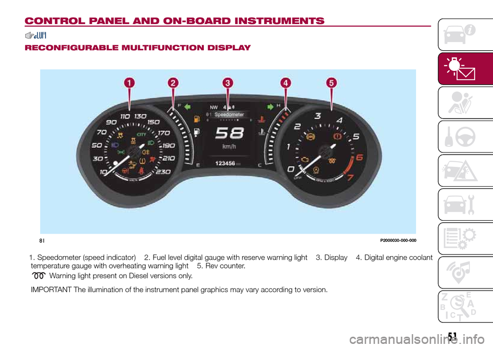
CONTROL PANEL AND ON-BOARD INSTRUMENTS
RECONFIGURABLE MULTIFUNCTION DISPLAY
1. Speedometer (speed indicator) 2. Fuel level digital gauge with reserve warning light 3. Display 4. Digital engine coolant
temperature gauge with overheating warning light 5. Rev counter.
Warning light present on Diesel versions only.
IMPORTANT The illumination of the instrument panel graphics may vary according to version.
81P2000030-000-000
51
Page 55 of 264
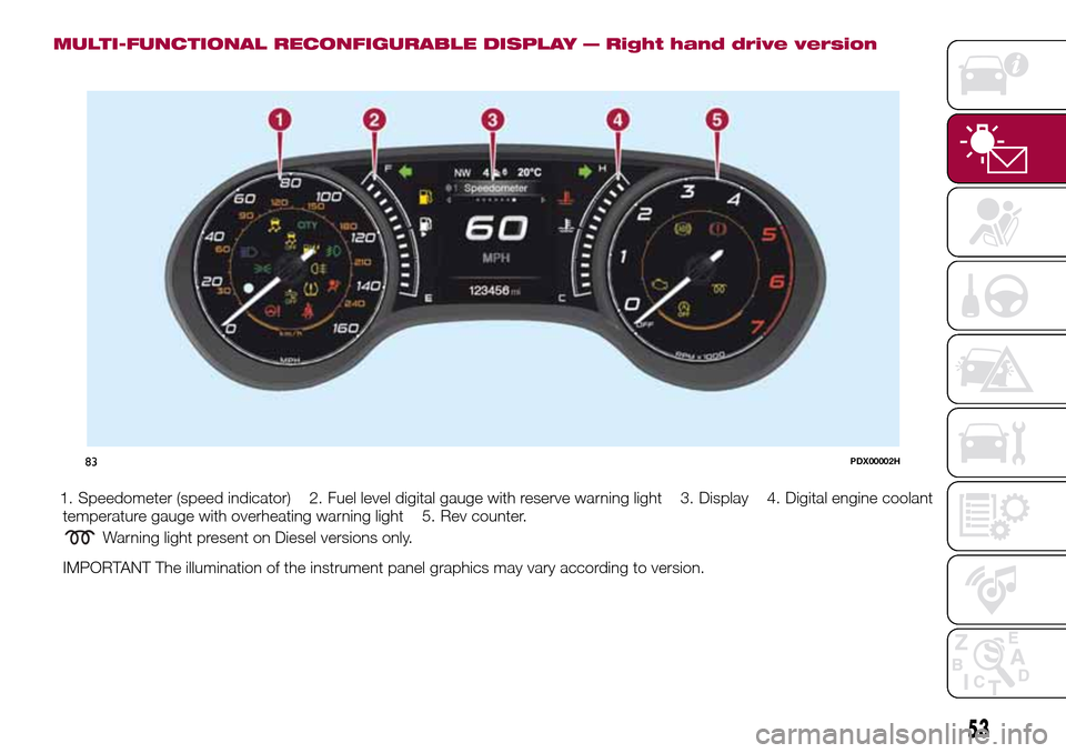
MULTI-FUNCTIONAL RECONFIGURABLE DISPLAY — Right hand drive version
1. Speedometer (speed indicator) 2. Fuel level digital gauge with reserve warning light 3. Display 4. Digital engine coolant
temperature gauge with overheating warning light 5. Rev counter.
Warning light present on Diesel versions only.
IMPORTANT The illumination of the instrument panel graphics may vary according to version.
83PDX00002H
53
Page 63 of 264

Warning light What it means
ENGINE COOLANT TEMPERATURE TOO HIGH
The warning light on the display lights up when the engine has overheated.
In normal driving conditions: stop the car, switch off the engine and check that the coolant level in the
reservoir is not below the MIN mark. In this case, wait for the engine to cool down, then slowly and
carefully open the cap, top up with coolant and check that the level is between the MIN and MAX marks
on the reservoir itself. Also check visually for any fluid leaks. If, when restarting, the warning light on the
display switches on again, contact a Fiat Dealership;
If the vehicle is used under demanding conditions(e.g. in high-performance driving): slow down
and, if the warning light stays on, stop the vehicle. Stop for two or three minutes with the engine running
and slightly accelerated to facilitate better coolant circulation, then turn the engine off. Check that the
coolant level is correct as described above.
IMPORTANT Over demanding routes, it is advisable to keep the engine running and slightly accelerated
for a few minutes before turning it off.
AIRBAG FAILURE
If the warning light switches on constantly, this indicates a failure in the airbag system.
34) 35)
WARNING
34)If, when the ignition device is turned to MAR, thewarning light does not switch on or stays on whilst driving, a failure may have
occurred in the restraint systems. In this case the airbags or pretensioners may not be deployed in an impact or, in a lower number of cases,
they may be deployed accidentally. Before continuing, contact a Fiat Dealership immediately to have the system checked.
35)The failure of the
warning light is signalled by the lighting up of thesymbol on the instrument panel display (or, for versions where
provided, by the flashing of the generic failure warning light). In this case, the warning light may not indicate any faults with the restraint
systems. Before continuing, contact a Fiat Dealership immediately to have the system checked
61
Page 120 of 264
The systemcannotbe set:
when pressing the brake pedal;
when the manual parking brake has
been operated;
when the brakes are overheated;
when the gear lever is in R (reverse),
neutral or in 1st (first gear engaged);
when the clutch is pressed;
when the vehicle speed is not within
the settable speed range;
when the engine rpm is above a
maximum threshold or below a
minimum threshold;
when the ESC (or ABS or other
stability control systems) are operating
or have just operated;
during automatic braking by the Full
Brake Control system;
when the Speed Limiter is active;
when the electronic Cruise Control is
active;
in case of failure of the device;
when the engine is off;
in case of obstruction of the radar
sensor (in this case the bumper area
where it is located must be cleaned).
In case of system set, the conditions
described above also cause a
cancellation or deactivation of the
system with times that may vary
according to the conditions.
IMPORTANT With the device set, it is
possible to reach speeds higher thanthose set in the system (or equivalent
in mph) by pressing the accelerator
pedal. In this situation, the device does
not turn off automatically, but the
device’s functions are limited: it is
therefore recommended to turn it off.
CHANGING SPEED
Increasing speed
After having set the device, the stored
speed can be stored by holding the
SET + button pressed.
Press the SET + button once, the set
speed will increase by 1 km/h (or the
equivalent in mph). Each subsequent
touch of the button will increase the
speed by 1 km/h (or the equivalent
in mph).
Hold the SET + button down, the set
speed will increase in 10 km/h steps (or
the equivalent in mph) until the button is
released. The set speed increase is
shown on the display.
Decreasing speed
After having set the device, the stored
speed can be reduced by holding the
SET –. button down.
Press the SET – button once, the set
speed will decrease by 1 km/h (or the
equivalent in mph). Each subsequent
touch of the button will reduce the
speed by 1 km/h (or the equivalent
in mph).Hold the SET – button down, the set
speed will decrease in 10 km/h steps
(or the equivalent in mph) until the
button is released. The set speed
decrease is shown on the display.
IMPORTANT NOTES
By keeping the accelerator pedal
depressed, the vehicle can continue to
accelerate beyond the set speed. In this
case, press SET + (or SET–)tosetthe
speed to the current speed of the
vehicle.
When the SET – button is pressed to
reduce the speed, the braking system
intervenes automatically if the engine
brake does not slow the vehicle down
sufficiently to reach the set speed.
The device holds the set speed uphill
and downhill; however a slight variation
is entirely normal, particularly on slight
gradients.
Gears can be shifted during operation
of the device to allow to select the gear
suited to the set speed and keep the
device set. The device is cancelled
when you press and hold the clutch
pedal down or putting the gear lever in
the neutral position for more than a
certain time limit.
The device is switched off while driving
if the brakes overheat.
118
STARTING AND DRIVING
Page 157 of 264
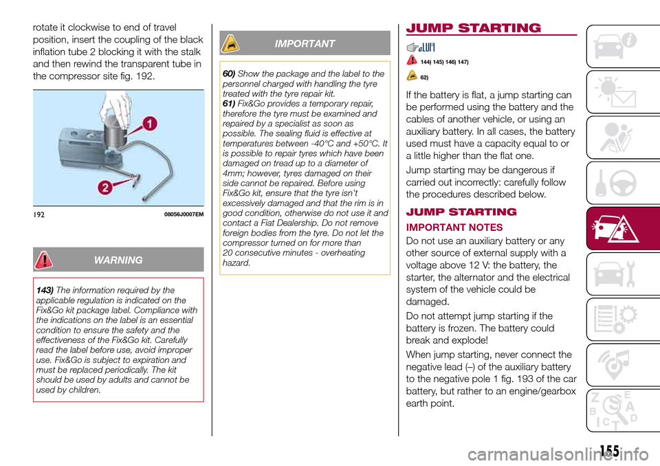
rotate it clockwise to end of travel
position, insert the coupling of the black
inflation tube 2 blocking it with the stalk
and then rewind the transparent tube in
the compressor site fig. 192.
WARNING
143)The information required by the
applicable regulation is indicated on the
Fix&Go kit package label. Compliance with
the indications on the label is an essential
condition to ensure the safety and the
effectiveness of the Fix&Go kit. Carefully
read the label before use, avoid improper
use. Fix&Go is subject to expiration and
must be replaced periodically. The kit
should be used by adults and cannot be
used by children.
IMPORTANT
60)Show the package and the label to the
personnel charged with handling the tyre
treated with the tyre repair kit.
61)Fix&Go provides a temporary repair,
therefore the tyre must be examined and
repaired by a specialist as soon as
possible. The sealing fluid is effective at
temperatures between -40°C and +50°C. It
is possible to repair tyres which have been
damaged on tread up to a diameter of
4mm; however, tyres damaged on their
side cannot be repaired. Before using
Fix&Go kit, ensure that the tyre isn't
excessively damaged and that the rim is in
good condition, otherwise do not use it and
contact a Fiat Dealership. Do not remove
foreign bodies from the tyre. Do not let the
compressor turned on for more than
20 consecutive minutes - overheating
hazard.
JUMP STARTING
144) 145) 146) 147)
62)
If the battery is flat, a jump starting can
be performed using the battery and the
cables of another vehicle, or using an
auxiliary battery. In all cases, the battery
used must have a capacity equal to or
a little higher than the flat one.
Jump starting may be dangerous if
carried out incorrectly: carefully follow
the procedures described below.
JUMP STARTING
IMPORTANT NOTES
Do not use an auxiliary battery or any
other source of external supply with a
voltage above 12 V: the battery, the
starter, the alternator and the electrical
system of the vehicle could be
damaged.
Do not attempt jump starting if the
battery is frozen. The battery could
break and explode!
When jump starting, never connect the
negative lead (–) of the auxiliary battery
to the negative pole 1 fig. 193 of the car
battery, but rather to an engine/gearbox
earth point.
19208056J0007EM
155
Page 184 of 264
75)Always require the use of only
compressor coolants and lubricants
approved and suitable for the specific air
conditioning system fitted on the vehicle.
Some non-approved coolants are
flammable and may explode, with the risk
of injuries. The use of non-approved
coolants or lubricants may adversely affect
system efficiency, leading to expensive
repairs.
76)The air conditioner system contains
coolant under high pressure: to avoid
injuries to people or damage to the system,
any coolant addition or repair that requires
to disconnect the cables must be carried
out by a Fiat Dealership.
77)Vehicles equipped with catalytic
converter must be fuelled only with
unleaded petrol. Leaded petrol would
permanently damage the catalytic
converter and eliminate its ability to reduce
polluting emissions, seriously
compromising the engine performance,
which would be irreparably damaged. If the
engine does not work correctly, especially if
it starts irregularly or if there is a reduction
of its performance, immediately go to a Fiat
Dealership. Prolonged and faulty operation
of the engine may cause overheating of the
converter and, as a consequence, possible
damage to the converter and the vehicle.LIFTING THE
VEHICLE
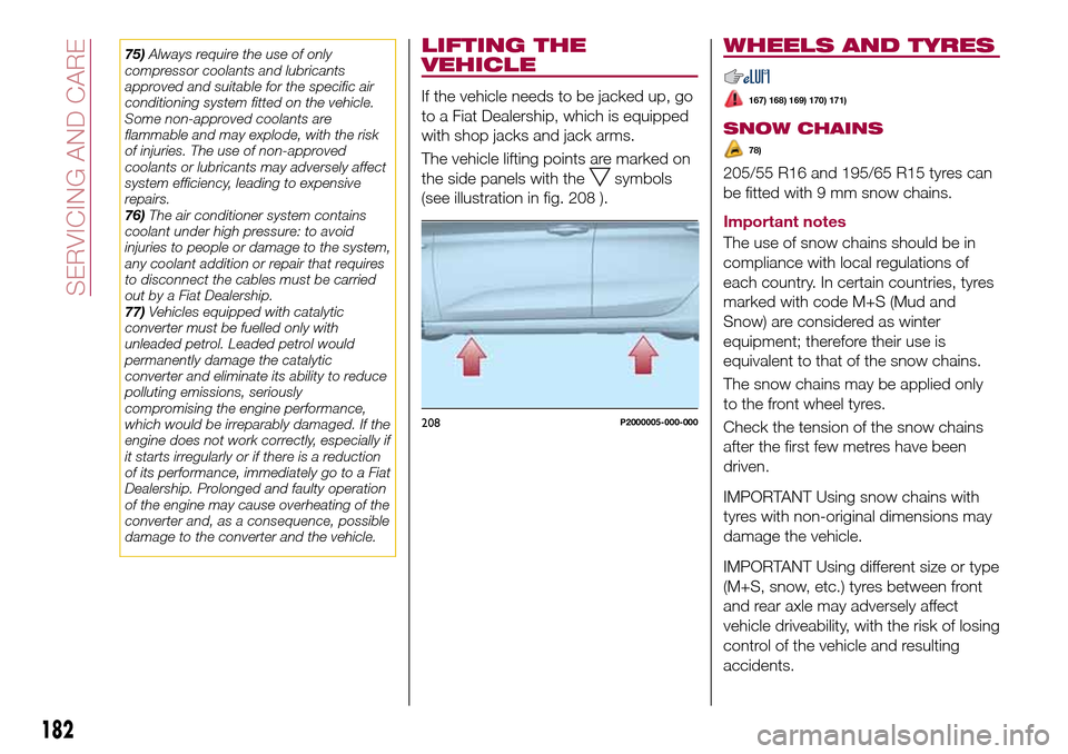
If the vehicle needs to be jacked up, go
to a Fiat Dealership, which is equipped
with shop jacks and jack arms.
The vehicle lifting points are marked on
the side panels with the
symbols
(see illustration in fig. 208 ).
WHEELS AND TYRES
167) 168) 169) 170) 171)
SNOW CHAINS
78)
205/55 R16 and 195/65 R15 tyres can
be fitted with 9 mm snow chains.
Important notes
The use of snow chains should be in
compliance with local regulations of
each country. In certain countries, tyres
marked with code M+S (Mud and
Snow) are considered as winter
equipment; therefore their use is
equivalent to that of the snow chains.
The snow chains may be applied only
to the front wheel tyres.
Check the tension of the snow chains
after the first few metres have been
driven.
IMPORTANT Using snow chains with
tyres with non-original dimensions may
damage the vehicle.
IMPORTANT Using different size or type
(M+S, snow, etc.) tyres between front
and rear axle may adversely affect
vehicle driveability, with the risk of losing
control of the vehicle and resulting
accidents.
208P2000005-000-000
182
SERVICING AND CARE