Page 145 of 264

at the same time slowly rotate the
screw anticlockwise, until resistance is
encountered (do not overtighten);
slowly release the screw;
opening is indicated by the entire
screw head coming out of its housing;
remove cover 2, sliding it upwards
on the side guides, as indicated in the
figure.
The number identifying the electrical
component corresponding to each fuse
is shown on the cover.
Once the fuse has been replaced,
proceed as follows:
correctly refit the cover 2 in the side
guides of the casing;
slide it down completely from the
top;
fully tighten screw 1 using the
screwdriver provided;
at the same time slowly rotate the
screw clockwise, until resistance is
encountered (do not overtighten);
slowly release the screw;
closure is indicated by the securing
of the entire screw head in its housing.
DASHBOARD FUSE BOX
Left-hand drive version
The fuse box fig. 164 is located to the
left side of the steering column. To
access the fuses, remove the snap
cover showed in fig. 163, pulling
towards yourself.
Right hand drive version
The control unit fig. 164 is located to
the left side under the dashboard.
To access the control unit, remove the
glove compartment using device 1
fig. 165.
16208036J0006EM
16306106J0005EM
16408036J0009EM
143
Page 146 of 264
UNDER DASHBOARD
CONTROL UNIT
The control unit fig. 166 is located to
the left side under the dashboard.
LUGGAGE
COMPARTMENT FUSE
BOX
Open the tailgate and then move the
section of the inner cover fig. 167 (TIPO
5DOOR version) or fig. 168 (TIPO
STATION WAGON version) and access
the fuses in fuse box 2fig. 169.
165P2000138
166P2000083-000-000
167P1030208-000-000
168P2000136
16908036J0011EM
144
IN AN EMERGENCY
Page 147 of 264
ENGINE COMPARTMENT CONTROL UNIT
fig. 161
USERSFUSE AMPERE
Two-tone horn F10 15
Heater mirrors F88 7.5
Heated rear window F20 30
Active Grille Shutter F84 5
DASHBOARD FUSE BOX
fig. 164
USERSFUSE AMPERE
Front electric window (driver side) F47 25
Front electric window (passenger side) F48 25
Supply forUconnect
™system, Climate Control system, EOBD
system, USB/AUX port, steering wheel controls.F36 15
Dead Lock device (Driver side door unlocking for
versions/markets, where provided)/Door unlocking/Central
locking/Electric tailgate unlockingF38 20
Windscreen washer pump F43 20
Rear left electric window F33 25
Rear right electric window F34 25
145
Page 148 of 264
UNDER DASHBOARD CONTROL UNIT
fig. 166
USERSFUSE AMPERE
Front door unlocking (driver side) 1 7.5
Front door unlocking (passenger side) 2 7.5
Rear door unlocking (left) 3 7.5
Rear door unlocking (right) 4 7.5
LUGGAGE COMPARTMENT FUSE BOX
fig. 169
USERSFUSE AMPERE
Rear 12 V socket F97 15
Driver's front seat heater F99 10
Passenger side front seat heater F92 10
Driver's front seat lumbar adjustment F90 10
WARNING
134)If the replaced fuse blows again, contact a Fiat Dealership.
135)Never replace a fuse with another with a higher amp rating; DANGER OF FIRE
136)If a fuse NOT indicated in this or the previous page is used, contact a Fiat Dealership.
137)Before replacing a fuse, make sure that the ignition device is at STOP, that the key, if mechanical, has been removed and that all devices
are switched off and/or disconnected.
146
IN AN EMERGENCY
Page 149 of 264
IMPORTANT
56)Never replace a fuse with metal wires or anything else.
57)If it is necessary to wash the engine compartment, take care not to directly hit the fuse box and the window wiper motor with the water jet.
147
Page 150 of 264

CHANGING A WHEEL
JACK
Please note that:
the jack weight is 2.15 kg;
the jack cannot be repaired and in
the event of a fault it must be replaced
by another genuine one;
No tool other than its cranking device
may be fitted on the jack.
Servicing
Prevent any dirt from depositing on
the "worm screw";
Keep the "worm screw" lubricated;
Never modify the jack.
Conditions for non-use
Temperatures below −40°C;
On sandy or muddy ground;
On uneven ground;
On steep roads;
In extreme weather conditions:
thunderstorms, typhoons, hurricanes,
blizzards, storms, etc.
In direct contact with the engine or
for repairs under the vehicle;
On boats.
CHANGING PROCEDURE
138) 139) 140) 141) 142)
58) 59)
Proceed as follows:
stop the car in a position that is not
dangerous for oncoming traffic where
you can change the wheel safely. The
ground must be flat and sufficiently
compact;
stop the engine, engage the hazard
warning lights and the parking brake;
engage first gear or reverse;
wear the reflective safety jacket
before getting out of the car (anyway
comply with the laws in force in the
country you are driving in);
open the luggage compartment and
if there is a cargo box (for TIPO 5DOOR
version only), remove it as described in
the “Cargo box” paragraph in the
“Getting to know the car” chapter (for
petrol and diesel versions only);
lift the mat and fix it by the tab to the
fastening device on the parcel shelf
fig. 170 (for TIPO 5DOOR version only);
using the tool 4 in the tool box, undo
the lock nut 1 fig. 171 (for TIPO 5DOOR
version) or fig. 172 (for TIPO STATION
WAGON version);
170P2000069-000-000
171P2000059-000-000
148
IN AN EMERGENCY
Page 151 of 264
take out the toolbox 3 and bring it
next to the wheel to be replaced;
take the spare wheel or the
space-saver wheel 2 (for TIPO 5DOOR
version);
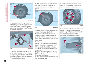
for versions with steel rim: remove
the hub cap 1 fig. 173 using the
specific tool 2 fig. 174, located in the
tool container: grip the tool with two
fingers, insert the tongue between tyre
and hub cap and pull towards yourself
perpendicular to the wheel;
take the chock 1 fig. 175 and fold it
out as shown in the diagram;
place the chock 1 on the wheel
diagonally opposite the one to be
replaced (see fig. 176 ) to prevent the
vehicle from moving irregularly when it
is lifted from the ground;
loosen the bolt of the wheel to be
replaced by about one turn with the
wrench provided 1 fig. 177; rock the car
to make it easier to separate the rim
from the wheel hub;
172P200012517308046J0012EM
17408046J0013EM
17508046J0007EM
17608046J0004EM
149
Page 152 of 264

operate the device 1 fig. 178 to
extend the jack until the top of the jack
2 fits correctly into the side member
3 of the vehicle, next to the
symbol
on the side member;
alert any bystander that the car is
about to be raised; all persons should
be kept away from the car and nobody
must touch it until it has been lowered;
operate the jack handle 1fig. 178 (clockwise) to operate the jack
and raise the car until the wheel is
raised a few centimetres above the
ground.
loosen the stud bolts completely and
remove the punctured wheel;
make sure the contact surfaces
between spare or space-saver wheel
(for TIPO 5DOOR version) and hub are
clean so that the fastening bolts will not
come loose;
fit the spare or space-saver wheel
(for TIPO 5DOOR version) by inserting
the first bolt for two threads into the
hole closest to the inflation valve and
proceed in the same manner with the
other bolts;
tighten the retaining bolts well using
wrench 1 fig. 177;
turn the jack handle 1
fig. 178 (anticlockwise) to lower the car
and remove the jack;
use the wrench provided to fasten
the bolts completely in a criss-cross
fashion as shown in fig. 180;
for versions with steel rim, fit the hub
cap on the spare wheel: make the
groove 1 fig. 181 provided on the hub
cap and highlighted by symbol
2 coincide with the inflation valve;
17708046J0005EM
17808046J0006EM
17908046J0001EM
180F1B0225C
18108046J0010EM
150
IN AN EMERGENCY