Page 241 of 266

a:,
a:,
...... N
" N .... 0
0
LL co
@ Tips
The discharged battery must be properly con┬Ł
nected to the vehicle's electrical system .
When jump starting or charg ing the battery,
never connect the negative ground cable to
the battery negative post because the battery
manager system must be able to detect the
battery's state of charge. Always connect the
negative ground cable to the negative ground
post of the battery manager control unit.
Use of jumper cables
Make sure to connect the jumper cable clamps in
exactly the order described below!
Fig. 196 Engine compartment: Connectors fo r jumper ca┬Ł
bles and charger
Fig. 197 Jump starting with the battery of another vehicle:
@ booster battery, @ discharged vehicle battery
The procedure described below for connecting
jumper cables is intended to provide a jump start
for your vehicle.
Vehicle with discharged battery: .. Turn off lights and accessories, move lever of
automatic transmission to N (Neutral) or P
(Park) and set parking brake.
Emergency situations
Connect POSITIVE(+) to POSITIVE (+) (red)
.. Remove the cover above the jump start connec┬Ł
tion.
.. Open the cover on the positive pole
c;, fig. 196.
1. Connect one end of the red positive cab le on
the jump start bolt
c;, fig. 197@ (Bolts un┬Ł
der cover= "positive") of the vehicle to be
started @.
2. Connect the other end to the positive termi-
nal @ of the booster battery @.
Connect NEGATIVE(-) to NEGATIVE(-) (black)
3. Connect one end of the black negative cable
to the negative te rm i nal @of the booster
battery @.
4. Connect the other end to the jump start bolt
@ (Bolts with hex head= "negative") of the
vehicle to be started @.
Starting the engine
"' Start the engine of the vehicle with the booster
battery @. Run the engine at a moderate
speed.
"' Start engine w ith discharged vehicle battery@
in the usual manner.
"' If the eng ine fails to start: do not keep the
starter cranking for longer than 10 seconds.
Wait for about 30 seconds and then try again.
"' With engine running, remove jumper cables
from both vehicles in the exact
reverse order .
"' Close the cover on the positive pole.
The battery is vented to the outside to prevent gases from entering the vehicle interior. Make
sure that the jumper clamps are well connected
with their
metal parts in full contact with the
battery term inals.
_&. WARNING
To avoid serious personal injury and damage
to the veh icle, heed all warnings and instruc┬Ł
tions of the jumper cable manufacturer. If in
doubt, call for road service.
- Jumper cables must be long enough so that
the vehicles do not touch. ""
239
Page 242 of 266

Emergency situations
-When connecting jumper cables, make sure
that they cannot get caught in any moving
parts in the engine compartment.
- Do not bend over the batteries -danger of
chemical burns!
- The battery cell locking screws must be
tightened securely.
- Before you check anything in the engine
compartment, always read and heed all
WARNINGS
i=> page 193.
(D Note
Improper hook-up of jumper cables can ruin
the generator.
- Always connect POSITIVE(+) to POSITIVE
(+), and NEGATIVE(-) to NEGATIVE(-)
ground post of the battery manager control
unit.
- Check that all screw p lugs on the battery
cells are screwed in firmly. If not, tighten
plugs prior to connect ing clamp on negative
battery terminal.
- Please note that the procedure for connect ┬Ł
i ng a jumper cable as described above ap┬Ł
plies specifically to the case of your vehicle
being jump started . When you are giving a
ju mp start to another vehicle, do
not con┬Ł
nect the negative (-) cable to the negative
(-) terminal on the discharged batte ry @
c> fig. 197. Instead, securely connect the
negative( -) cab le to either a solid metal
component that is firm ly bolted to the en┬Ł
gine block or to the engine block itself. If
the battery that is being charged does not
vent to the outside, escap ing battery gas
could ignite and explode!
Towing with a tow truck
General hints
Your Audi requires special handling for towing.
The following information is to be used by com┬Ł
mercial tow truck operators who know how to op┬Ł
erate the ir equipment safely.
-Never tow your Audi, towing will cause dam┬Ł
age to the engine and transmission.
240
-Never wrap the safety chains or winch cables
around the brake lines .
- To prevent unnecessary damage, your Audi
must be transported with a flat bed truck .
- To load the vehicle on to the flat bed, use the
towing loop found in the vehicle tools and at┬Ł
tach to the front or rear anchorage
i=> page 240 and c> page 241 .
A WARNING
A vehicle being towed is not safe for passen┬Ł
gers. Never allow anyone to ride in a vehicle
being towed, for any reason.
Front towing loop
Do not install the front towing loop until it is
needed.
Fig. 198 Front bumper: removing the cover cap
Fig. 199 Front bumper : sc rew ing in t he towing loop
The towing loop fits into the threaded hole locat┬Ł
ed on the right side o f the front bumper and cov┬Ł
ered by a small cover when not in use .
.,. Remove the towing loop from the vehicle tool┬Ł
ki t
c> page 227 .
.,. Press the cover in by applying short strong
pressure to the bottom part to release it from
the bumper
c> fig . 198 . Ill>
Page 243 of 266

.. Screw the towing loop tightly into the threaded
hole as far as it will go
~ fig. 199 and tighten it
with the wheel wrench.
When it is no longer needed, unscrew the towing
loop and put it back into the vehicle toolkit. Be
sure to have the towing loop stored in the vehicle
at all times.
A WARNING
If the towing loop is not screwed in as far as it
will go, the thread can pull out when the vehi┬Ł cle is towed - potential risk of an accident.
Rear towing loop
Do not install the rear towing loop until it is
needed.
Fig. 200 Rear bumper: cover
Fig. 201 Rear bumper: Screw ing in tow ing loop
co .,, N N
"" co co
On the r ight side of the rear bumper there is a
threaded hole for the towing loop. The threaded
hole is protected by a cover.
.. Remove the towing loop from the vehicle tool-
k it ¢
page 22 7 .
a:, ~ .,. Press the cover in by applying short strong
~ pressure to the bottom part to release it from N
8 the bumper ¢ fig. 200. 0 LL co
Emergency situations
.. Screw the towing loop tightly into the threaded
hole as far as it will go¢
fig. 201 and tighten it
w ith the wheel wrench.
Unscrew the towing loop again after use and in┬Ł
stall the cover in the bumper. Install the cover in
the bumper. Return the towing loop to the tool┬Ł kit. Be sure to have the towing loop stored in the
vehicle at all times.
A WARNING
-If the towing loop is not screwed in as far as it
will go, the thread can pull out when the vehi┬Ł
cle is towed - potential risk of an accident.
Loading the vehicle onto a flat bed truck
Fig. 202 Ve hicle on flat bed truck
Front hook up
.. Align the vehicle with the centerline of the car
carrier ramp .
.. Attach the winch hook to the front towline eye
previously installed .
Rear hook up
.. Align the vehicle with the centerline of the car
carrier ramp .
.. Attach the winch hook to the rear towline eye
previously installed .
(D Tips
Check carefully to make sure the hook-up is
secure before moving the car up the flatbed
truck ramp.
241
Page 244 of 266

Emergency situations
Raising the vehicle
Lifting with workshop hoist and with floor
jack
Th e vehicle may only b e lift ed at the lifting
poin ts illust rated.
F ig .. 203 F ro nt lift ing po int
F ig. 204 Rea r lifti ng po int
.,. Read and heed WARNING ¢ A-
.,. Locate lifti ng po ints ¢ fig . 203 and ¢ fig. 204 .
.,. Adjust lifting arms of wo rkshop hoist or floor
jack to match veh icle lifting points.
.,. In se rt a rubb er pad between t he floor jack/
wor kshop hoist a nd the lif ting poin ts .
If you must lift your vehicle with a floor jack to
work underneath, be sure the vehicle is safely
supported on stands intended for this purpose .
Front lifting point
The lift ing po int is located on the floo r pan re in┬Ł
forcement about at the same leve l as the jack
mo unt ing point ¢
fig. 203 . Do not lift the vehi┬Ł
cle at the vertical sill rei nforcement.
Rear lifting point
The lift ing po int is located on the vertica l re in┬Ł
for cement of the lower sill fo r the on board jack
¢fig. 204.
242
Lifting with vehicle jack
Refer to ~ page 231.
A WARNING
- To re duce the r is k of serious injury and vehi ┬Ł
cle dama ge .
- Always lift the vehicle o nly at the special
workshop hois t an d floor jack lift points il ┬Ł
l ustrat ed
~ fig. 203 and ~ fig. 2 04 .
-Failure to lift the v ehicle at these points
could ca use the veh icle to tilt or fall from
a lift if the re is a cha ng e i n ve hicle weigh t
dis tribu tion and ba lan ce . T his mig ht hap┬Ł
p en, for examp le, whe n he avy co mpo ┬Ł
n en ts such as the engine block o r tr an s┬Ł
mission are removed.
- W hen re m ov in g h eavy com ponen ts like
these, an cho r veh icle to hoist or ad d co rre ┬Ł
spond ing weights to ma inta in the ce nter of
gravity . Othe rw ise, the vehicle mi ght t ilt o r
slip off t he hoist, causing serious pe rsonal
in jur y.
(D Note
- Be aware of the fo llowing po ints befo re lift ┬Ł
ing the vehicle:
- The vehicle should never be lifted or
jacked up from underneath the engine oil pan, the transmission housing, the front
or rear axle or the body side members .
This could lead to serious damage .
- To avoid damage to the underbody or
chassis frame, a rubber pad must be in┬Ł
serted between the floor jack and the lift
points.
- Before driving over a workshop hoist,
check that the vehicle weight does not
exceed the permissible lifting capacity of
the hoist.
- Before driving over a workshop hoist , en┬Ł
sure that there is sufficient clearance be┬Ł
tween the hoist and low parts of the ve┬Ł
h icle .
Page 245 of 266
 plate: loca┬Ę
t ion on driver s side dash pane l
XXXXX X")
a:,
a:,
.... N
" N .... 0
0
LL co
Technical data
Vehicle identification
F ig . 2 05 Vehi cle Ident if ica tio n Number (VlN) plate: loca┬Ę
t ion on driver 's side dash pane l
XXXXX XX -X -XX XX X XX XX
CD+ ~t :1:: xxxxxxxx xx x xx xxx xxx
TVP/fffl XXX XXX
XX XXXXXXX XX X X xx
XXX KW XXX
┬«i ~:J ┬Ęf lfils~~ XXXX XXX XXX
®-+ ~ N:a=i~l xxxx ; xxxx xx x ; xx
II. ┬Ę AUSS, I OPTIONS
,__ __
E0 A 7D 5
2EH J0Z
3FC
F 0 A
TL 6 3KA
lXW
7T6 C V7
3L4
lS A 4UB
6XM 5SG
llB l AS
S M U 7Xl
9G3 0G7 0YH
8E H
UlA X98
803 908 824
7 K0 4 X3 2K2
4KC 3Y0 413
7GB
01 A
5R W
18A
0JF
Q Z7
020
502
4G0
XX . X XX X XX X XXXX
Fig. 206 Th e ve hicle identifica tion label: inside the lu g┬Ę
gage compartment
Veh icle Identification Number (VlN )
The Vehicle Identific ation N umbe r is locate d in
d if f eren t places:
- u nder the w indshield on the dr iver's side
~ fig . 205.
-in the radio or i n the MMI*: Select: !CAR! func┬Ł
t io n but ton
> Vehicle ID number (VIN) or se┬Ł
l e ct:
I CAR ! funct ion button > Car system s* con┬Ł
t rol but ton
> Servicing & che cks > VIN num┬Ł
ber .
-on the vehicle identific ation label.
Technical data
Vehicle identification label
T he vehicle identi fica tion label is lo cate d in t he
l uggage compa rtment near the ba ttery.
T he labe l
~ fig. 206 shows the fo llow ing vehicle
da ta:
(D Vehicle Identification Number (VIN)
@ Vehicle type, eng ine output, transm ission
@ Engine and transmission code
@ Paint number and interior
® Optional equipment numbers
T he information of the veh icle identification label
c an also be fo und in your Warran ty
& Mainte ┬Ł
nance booklet.
Safety compliance sticker
The safety compliance sticker is yo ur ass urance
t h at your n ew vehi cle complies w ith all appli cable
Fede ral Motor Vehicle Safety Stand ard s which
we re in effe ct at the time the veh icle w as m anu ┬Ł
fac tured. Yo u ca n fi nd this sticker on the door
jamb on the driver 's side. It shows the month and
year of production and t he ve hicle identification
number of your ve hicle (perforation) as well as
t h e Gross Vehicle Weight Rat ing (GVWR) and the
G ross Axle We ight Rati ng (GAWR).
H igh vo ltage warning label
T he hig h voltage warning label is located in the
engine compartment next to the engine hood re┬Ł
lease. The spark ignition system complies with
the Canadian standard ICES-002.
Weights
Gross Vehicle W eight Rating
The Gross Vehicle Weight Rating (GVWR), and
the Gross Axle Weight Rating (GAWR) for front
and rear a re listed on a sticker on the door jamb
o n the driver 's side .
T he Gross Vehicle Weight Rating includes the
weight o f the basic vehicle plus fu ll fuel tank, oil
and coolant, p lus maxim um load, which includes
passenger weight (150 lbs/68 kg per des ignated
seat ing pos ition) and luggage weight
c:> .&, . .,.
243
Page 246 of 266

Tech nical data
Gross Axle Weight Rating
The G ross Ax le We ight Rating is the max imum
load that can b e applied at each axle of the vehi ┬Ł
cle ¢& .
Vehicle capacity weight
The vehicle capacity we ight (max . load) is l isted
on the d river's side 8-p illar.
_& WARNING
- T he ac tual Gross Axle Weight Rating a t the
front and rear axles sho uld not exceed the
permissible weights, and their combination
must not exceed the Gross Veh icle Weight
Rating .
Dimensions
Length in (mm)
Width in (mm)
Width (across m irro rs) in (mm)
He ight (un loaded) al in (mm) -
Exceed ing permissible weight ratings can
result in vehicle damage, accidents and per┬Ł
sonal injury.
(D Note
- The vehicle capacity weight figures apply
when the load is d istr ibuted evenly in the
vehicle (passengers and luggage) . When
t ransporting a heavy load in the luggage
compartment, carry the load as near to the
rea r axle as possib le so that the vehicle's
hand ling is not impaired .
- Do not exceed the max imum perm iss ible
axle loads or the maximum g ross veh icle
we ight. Always remember that the ve hicle 's
han dling will be affe cted by the extra load .
T herefore , ad just your speed acco rd ingly.
- Always observe lo cal regulations.
AS Cabriolet SS Cabriolet
182.1 ( 4626) 182 .7 (46 40)
73.0 (1854) 73 .0 (1854)
7 9.5 (202 0) 79 .5 (2020)
54.4 (1383) 54 .3 (1380)
ŌĆó > T h e heigh t of the ve hicl e depends on the tir es and the s uspensio n.
When driving up steep ramps, on rough roads,
over curbs, etc . it is important to remember that
some parts of your vehicle , such as spoi le rs or ex-
Capacities
Fuel tank: tota l capacity
Windsh ield and headlight* washer fluid con ta iner
244
haust system components, may be close to the
ground . Be careful not to damage them .
gal (liters) 16.1 (6 1.0)
quarts (l ite rs) 4
.8 (4 .5)
Page 247 of 266
a:,
a:,
...... N r--. N ...... 0
0
LL 00
Technical dat a
Gasoline engines
AS Cabriolet 2.0, 4 cylinder
Maximum output SAE net hp@rpnn 220@ 4450-6000
Maximum torque SAE net lb
-ft@ rpm 259@ 1500-4300
Displacement CID (cm
3
) 121 (1984)
Engine oil with filter change
1>
Fuel Pr emium un lead ed (9 1 AKI )¢ page 188, Fuel
or Bio-ethanol (E S S) ¢ page 189, Ethanol fuel (Bio-etha-
no[) .
55 Cabriolet 3.0, 6 cylinder
Maximum output SAE net
Maximum torque SAE net
Displacement
Engine oil with filter changell
Fuel
1> For specific engine oil capac ities, please see
the most cur rent information fo r the USA at
http ://www.audiusa.com/he lp/ma intenance o r
for Canada at http ://www.audi.ca/ca/brand/ en/
your _aud i/ aud i_services_a nd/Ca re_and_M a i nte┬Ł
na nce/ schedu le.html or call 800-822-2834. hp@ rpm
333@ 5500-6500
lb-ft@rpm 325@ 2900-5300
CID (cm
3 ) 182.8 (2995)
Pr emium unl ead ed (91 AKI) ¢ page 188, Fuel
245
Page 248 of 266

Consumer information
Consumer information
Warranty coverages
Your Audi is covered by the following warran┬Ł
ties:
- New Vehicle Limited Warranty
- Limited Warranty Against Corrosion Perfora-
tion
- Emissions Control System Warranty
- Emissions Performance Warranty
- California Emissions Control Warranty (USA
vehicles only)
- California Emissions Performance Warranty
(USA vehicles only)
Detailed information regarding your warranties
can be found in your
Warranty & Maintenance
booklet .
Operating your vehicle
outside the U.S.A. or
Canada
Government regulati ons in the United States and
Canada require that automobi les meet specific
emission regulations and safety standards.
Therefore, vehicles built for the U.S.A. and Cana ┬Ł
da differ from vehicles sold in other countries.
If you plan to take your vehicle outside the conti┬Ł
nenta l limits of the United States or Canada,
there is the poss ibility that:
- un leaded fue ls for vehicles with catalytic con┬Ł
verter may not be available;
- fuel may have a considerably lower octane rat┬Ł
ing . Improper fuel may cause engine damage;
- service may be inadequate due to lack of proper
service facilities, tools or testing equipment;
- r eplacement parts may not be readily available.
- Nav igation systems for veh icles built for the
U.S .A . and Canada will not necessarily work in
Europe, and may not work in other countries
outside of North America.
246
(D Note
Audi cannot be responsib le for mechanical
damage that could result from inadequate
fuel, service or parts ava ilability.
Audi Service Repair
Manuals and Literature
Audi Official Factory Service Manuals and Litera ┬Ł
ture are published as soon as poss ible after mod┬Ł
el introduction . Service manuals and literature
are available to order from the Audi Technical Lit ┬Ł
erature Ordering Center at :
www.audi.techliterature .com
Maintenance
General '
Your vehicle has been designed to help keep
maintenance requirements to a minimum. How┬Ł
ever, a certain amount of regular maintenance is
still necessary to assure your vehicle's safety,
economy and reliability . For detailed vehicle
maintenance consult your Warranty & Mainte┬Ł
nance booklet .
Under difficult operating conditions, for exam ┬Ł
ple at extremely low outside temperatures, in
very dusty regions, when towing a trailer very fre┬Ł
quently, etc., some service work should be per┬Ł
formed between the intervals specified. This ap┬Ł
plies particularly to:
- oil changes, and
- cleaning or replac ing the a ir filter .
'
@) For the sake of the environment
By regularly maintain ing your vehicle, you
help make sure that em iss ion standards are
maintained, thus minimizing adverse effects
on the environment .
Important considerations for you and your
vehicle
The increasing use of electronics, sophisticated
fuel injection and emission control systems, and
the generally increas ing technica l complexity of ..,_
 1
1 2
2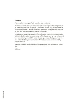 3
3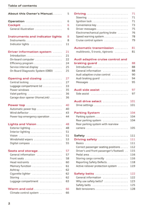 4
4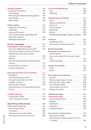 5
5 6
6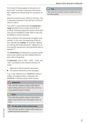 7
7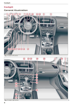 8
8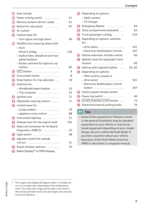 9
9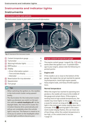 10
10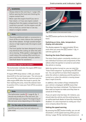 11
11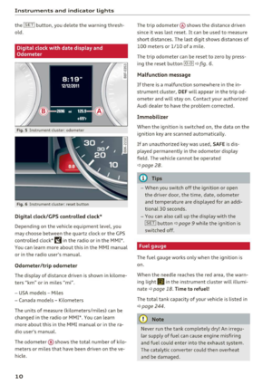 12
12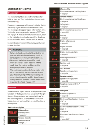 13
13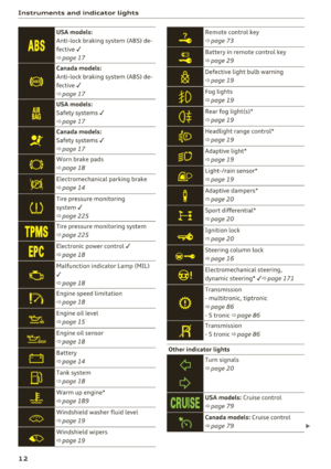 14
14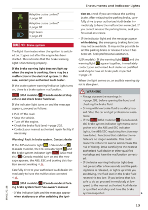 15
15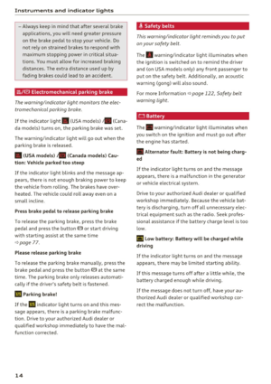 16
16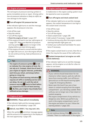 17
17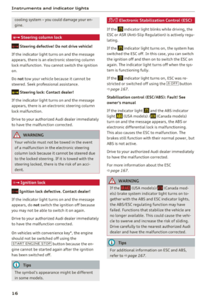 18
18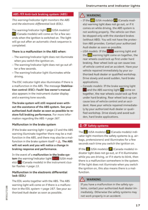 19
19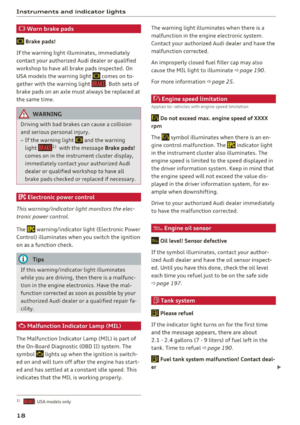 20
20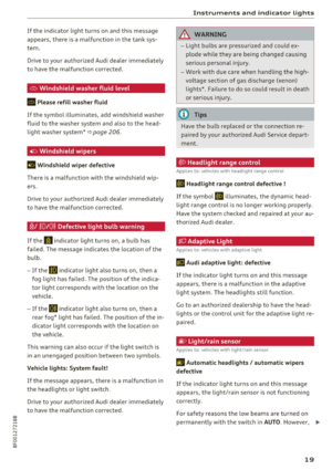 21
21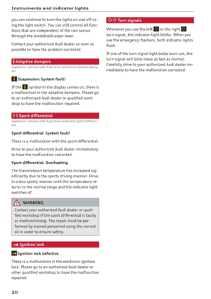 22
22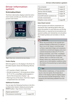 23
23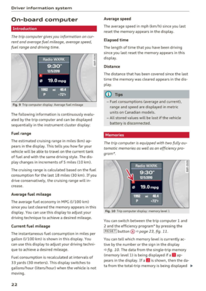 24
24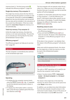 25
25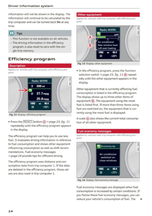 26
26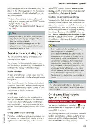 27
27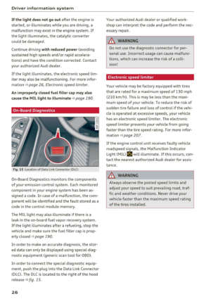 28
28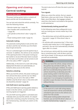 29
29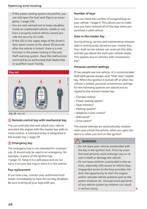 30
30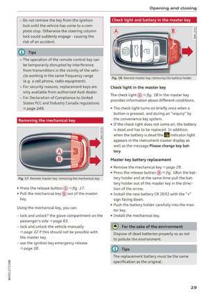 31
31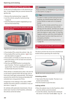 32
32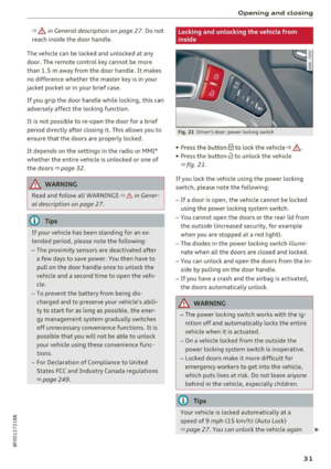 33
33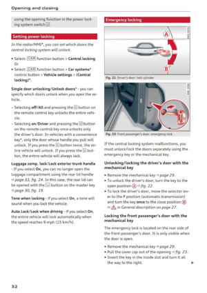 34
34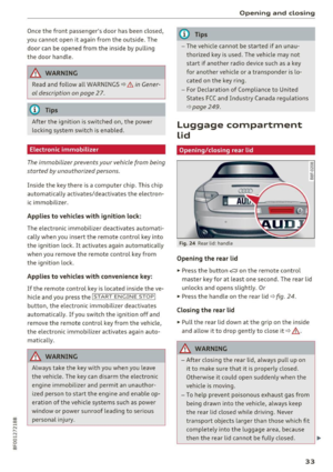 35
35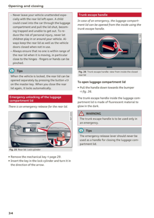 36
36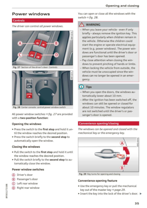 37
37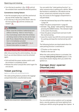 38
38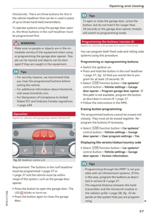 39
39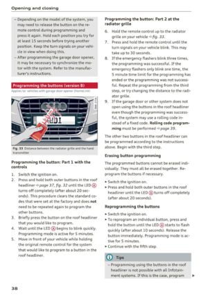 40
40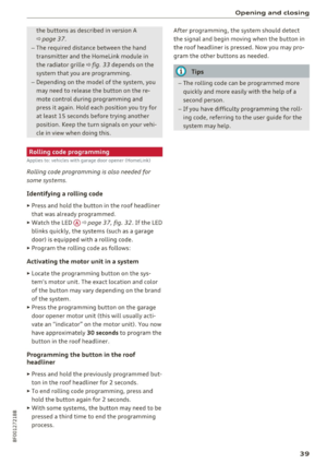 41
41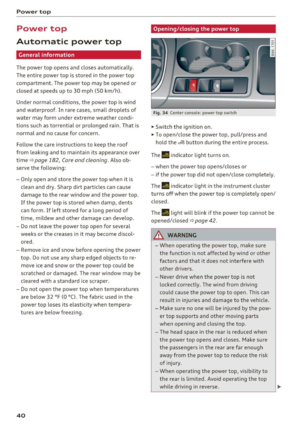 42
42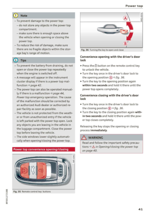 43
43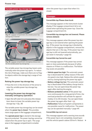 44
44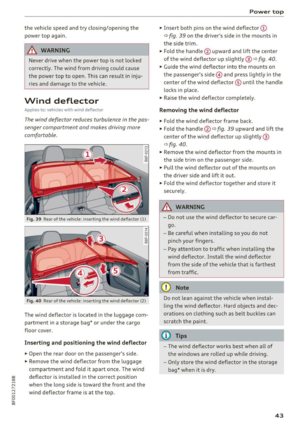 45
45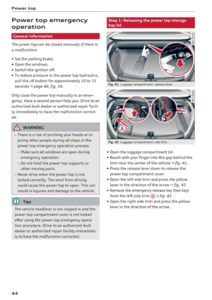 46
46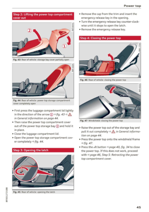 47
47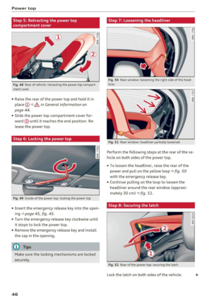 48
48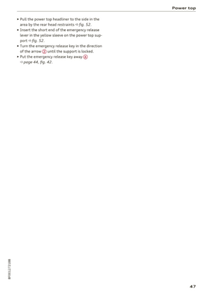 49
49 50
50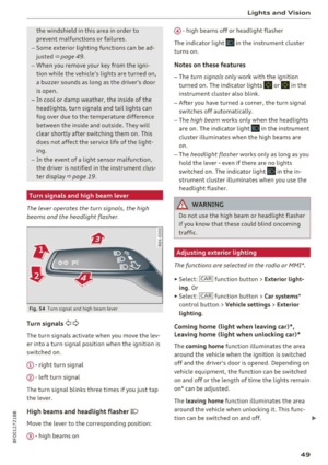 51
51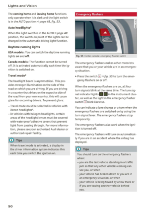 52
52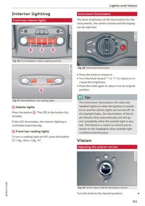 53
53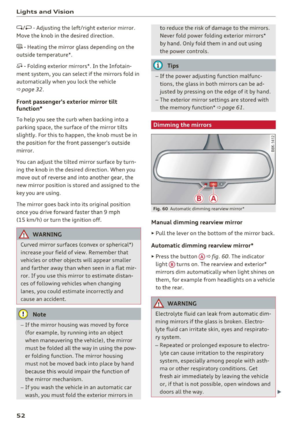 54
54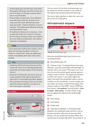 55
55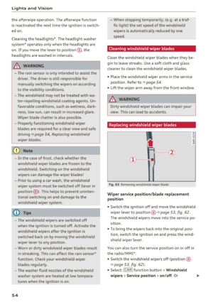 56
56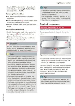 57
57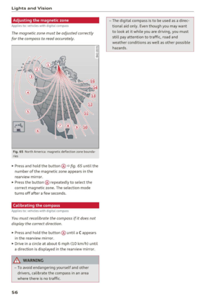 58
58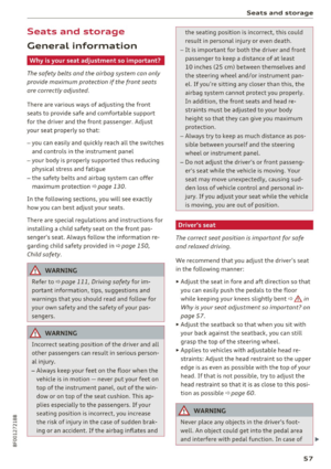 59
59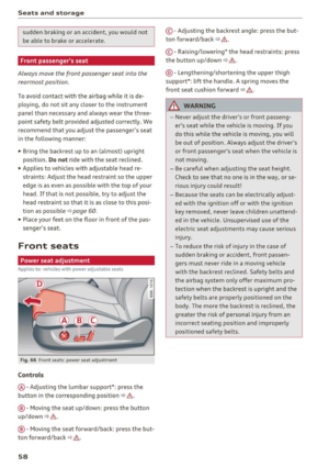 60
60 61
61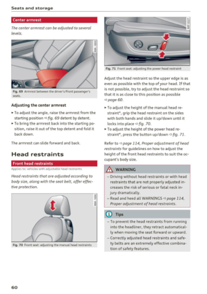 62
62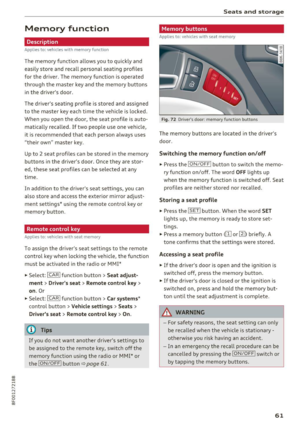 63
63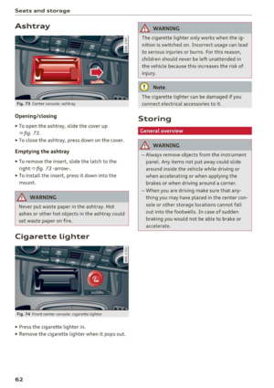 64
64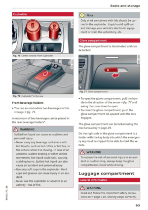 65
65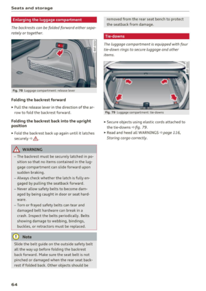 66
66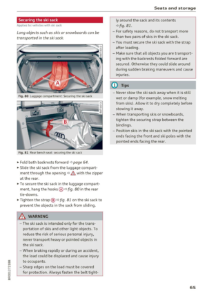 67
67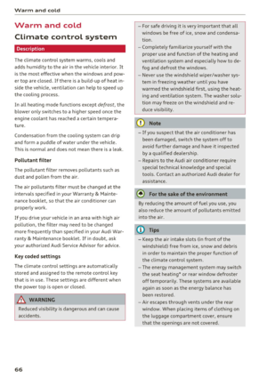 68
68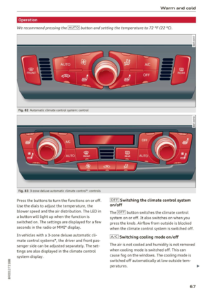 69
69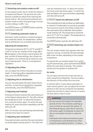 70
70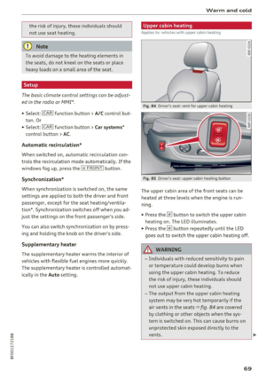 71
71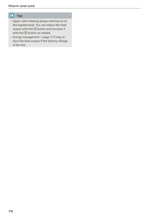 72
72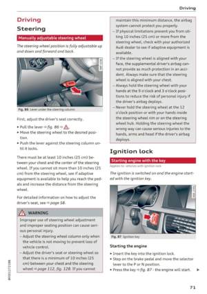 73
73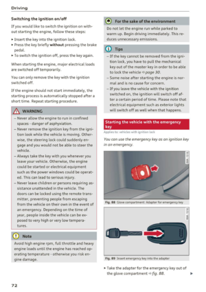 74
74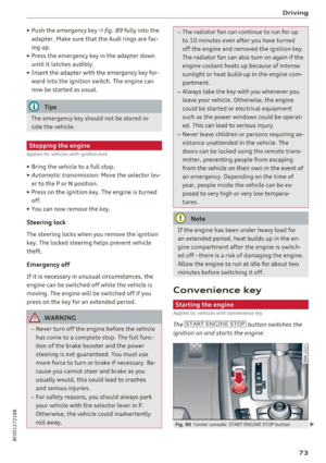 75
75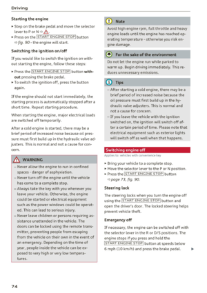 76
76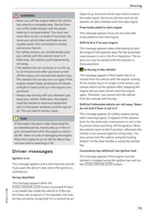 77
77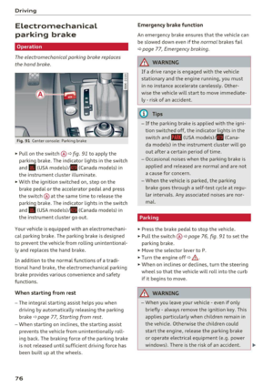 78
78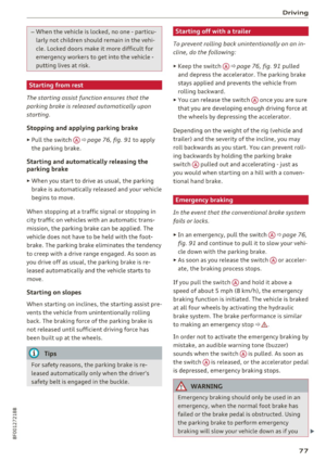 79
79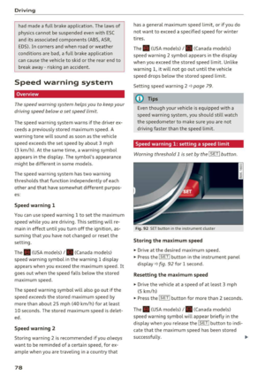 80
80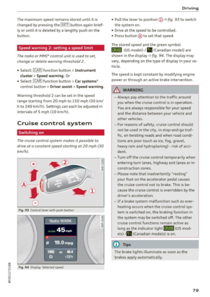 81
81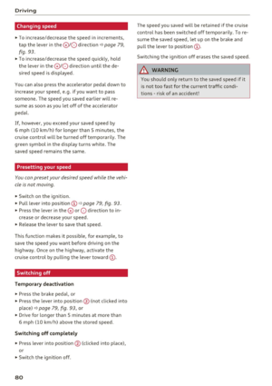 82
82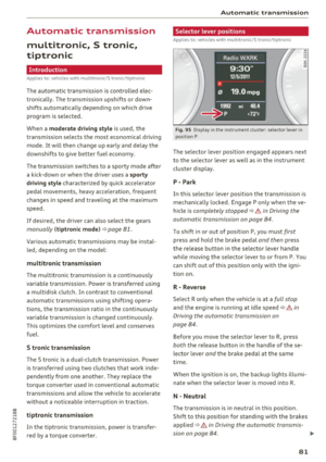 83
83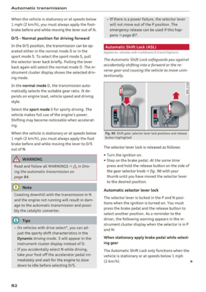 84
84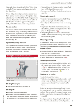 85
85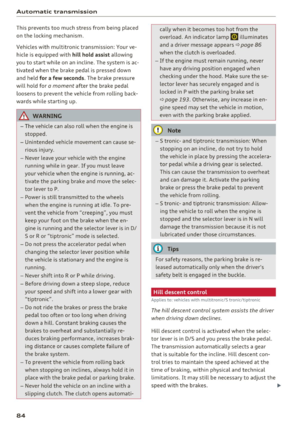 86
86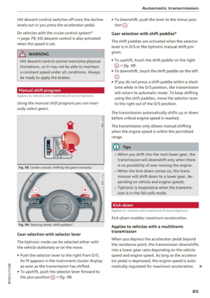 87
87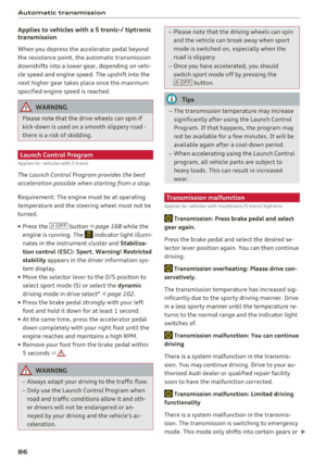 88
88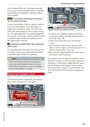 89
89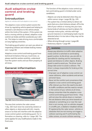 90
90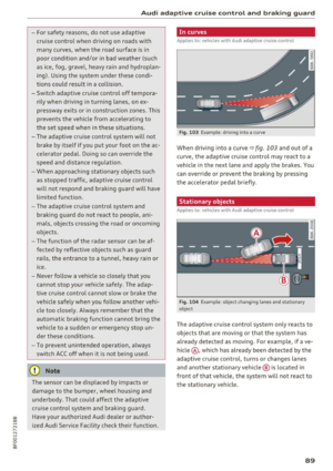 91
91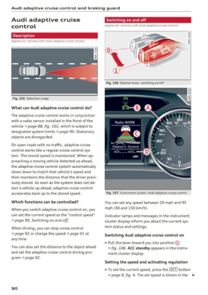 92
92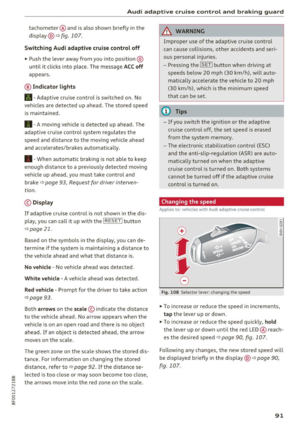 93
93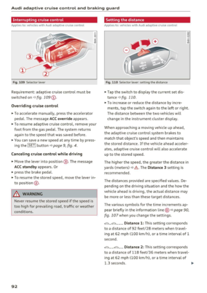 94
94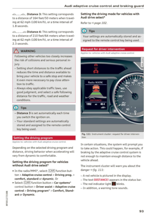 95
95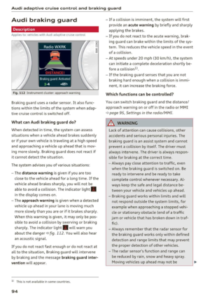 96
96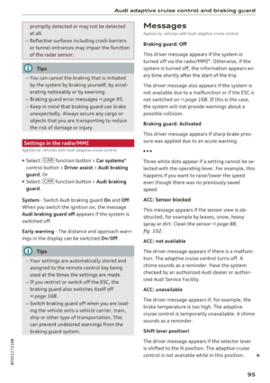 97
97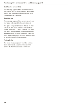 98
98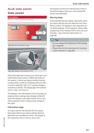 99
99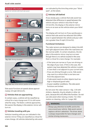 100
100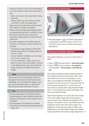 101
101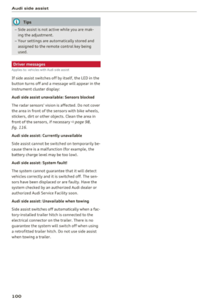 102
102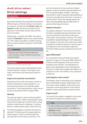 103
103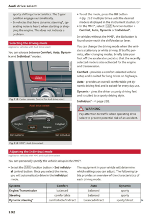 104
104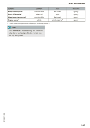 105
105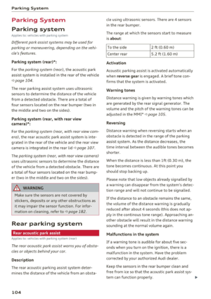 106
106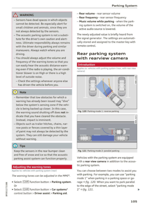 107
107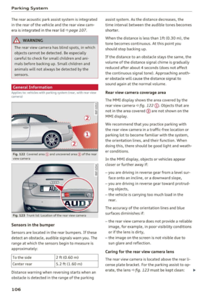 108
108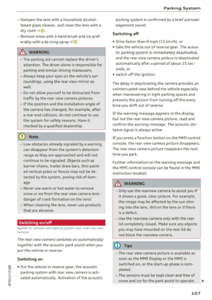 109
109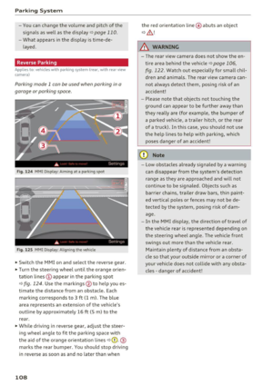 110
110 111
111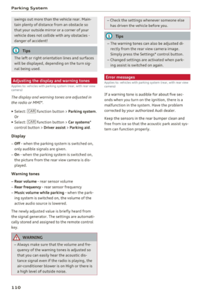 112
112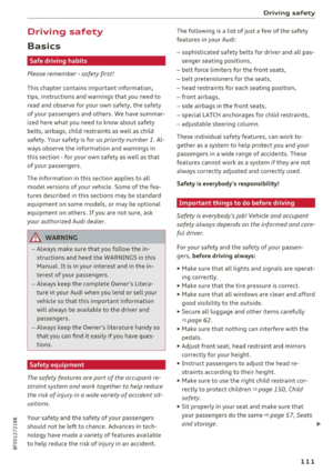 113
113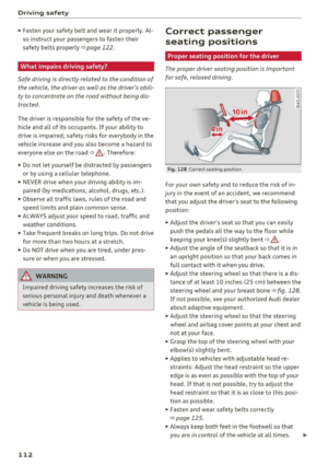 114
114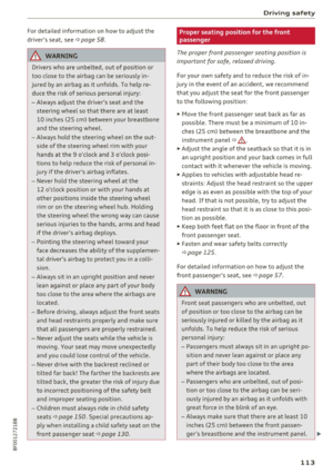 115
115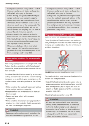 116
116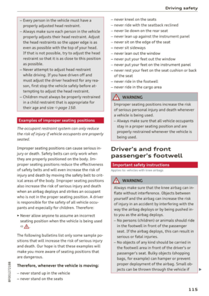 117
117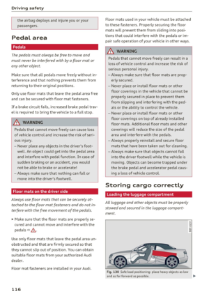 118
118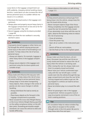 119
119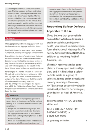 120
120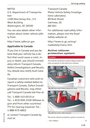 121
121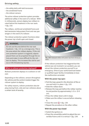 122
122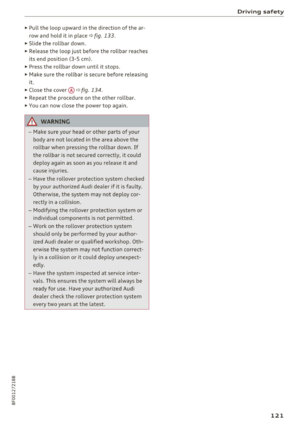 123
123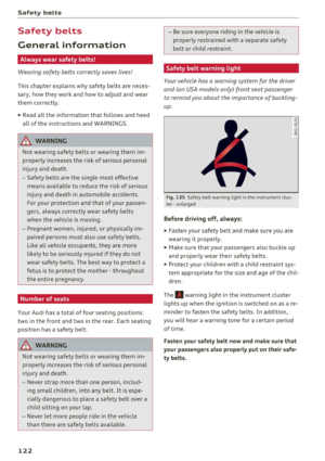 124
124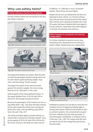 125
125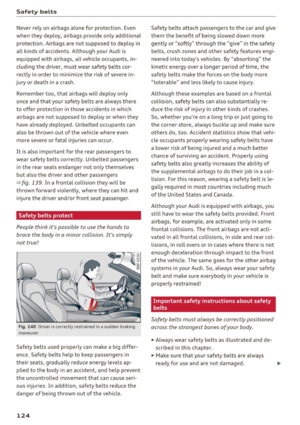 126
126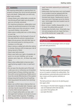 127
127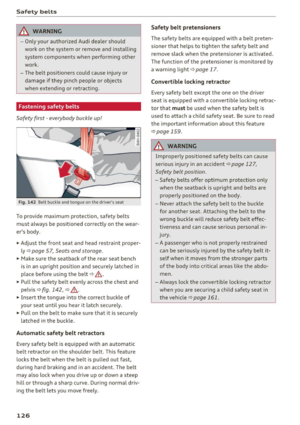 128
128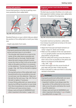 129
129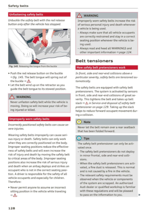 130
130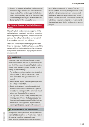 131
131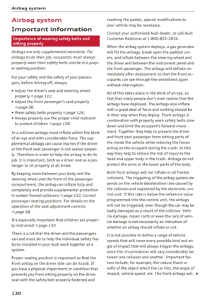 132
132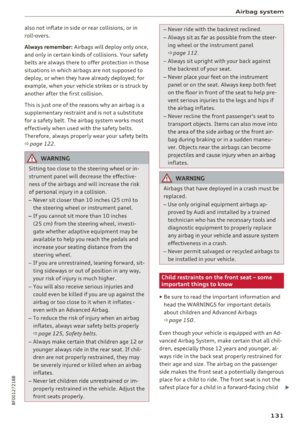 133
133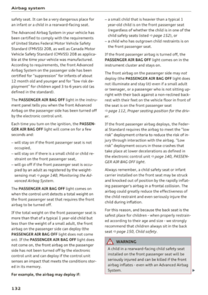 134
134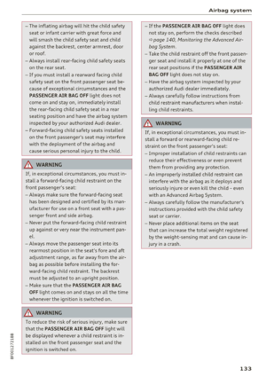 135
135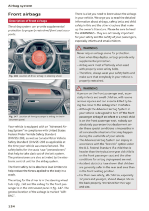 136
136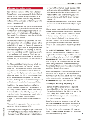 137
137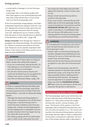 138
138 139
139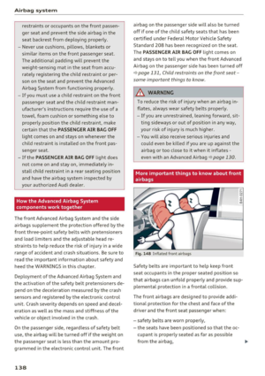 140
140 141
141 142
142 143
143 144
144 145
145 146
146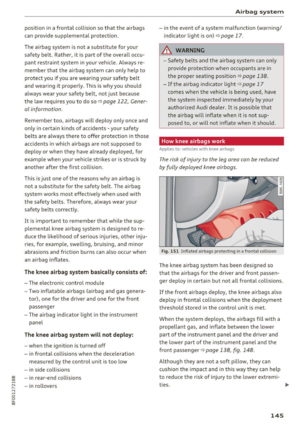 147
147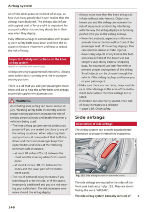 148
148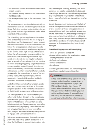 149
149 150
150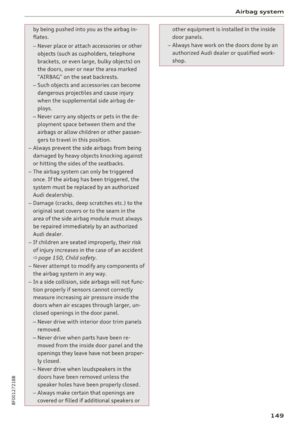 151
151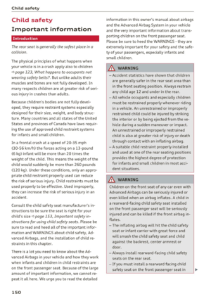 152
152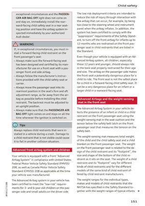 153
153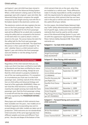 154
154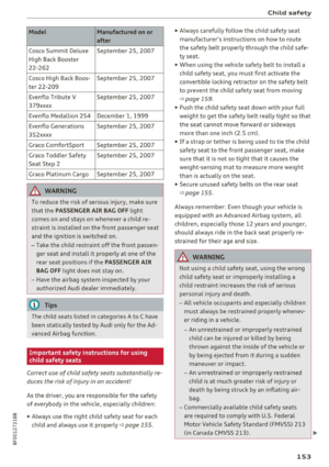 155
155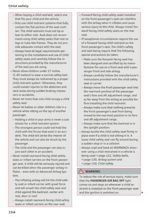 156
156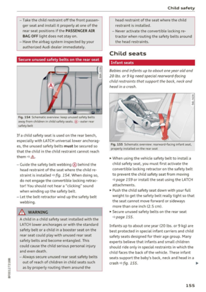 157
157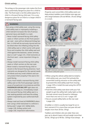 158
158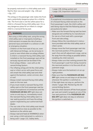 159
159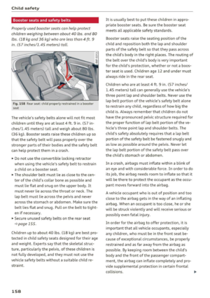 160
160 161
161 162
162 163
163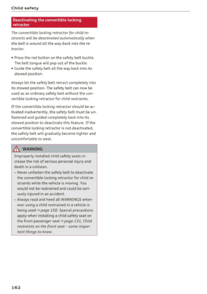 164
164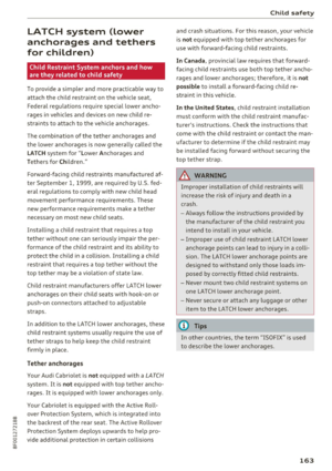 165
165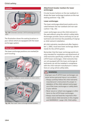 166
166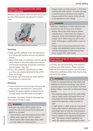 167
167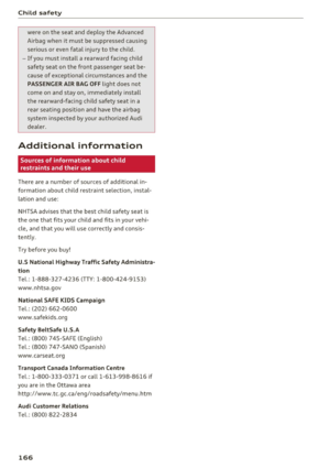 168
168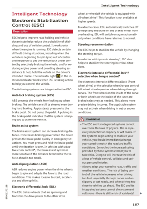 169
169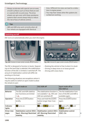 170
170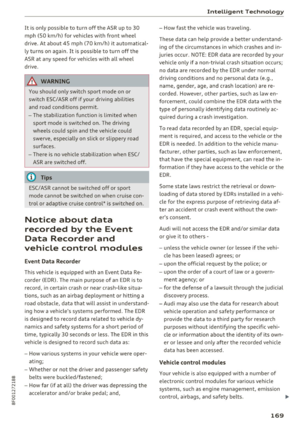 171
171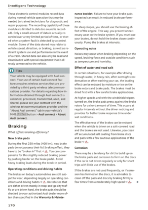 172
172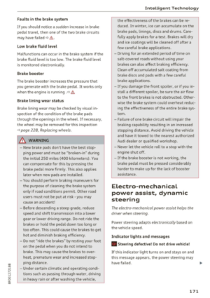 173
173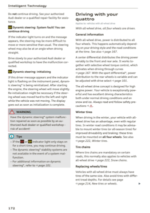 174
174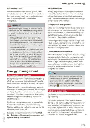 175
175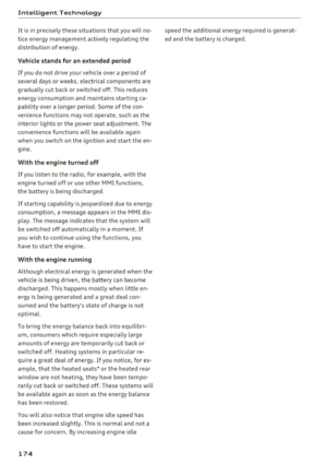 176
176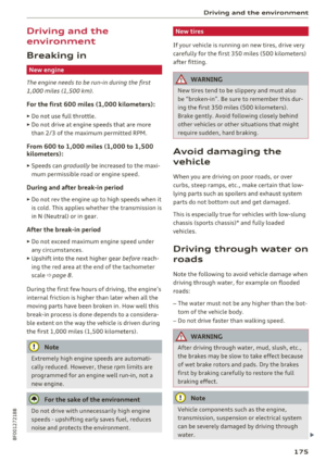 177
177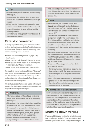 178
178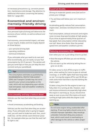 179
179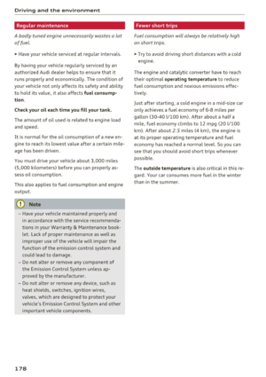 180
180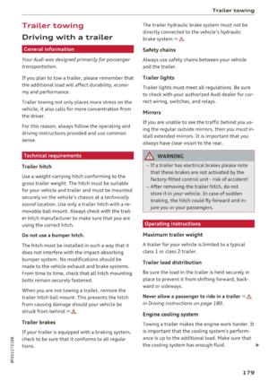 181
181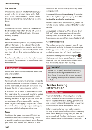 182
182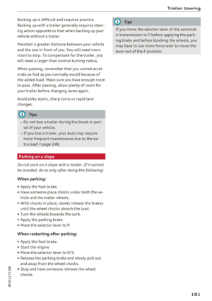 183
183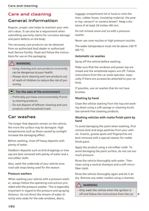 184
184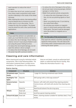 185
185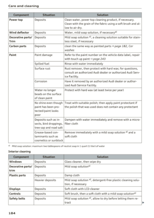 186
186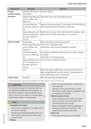 187
187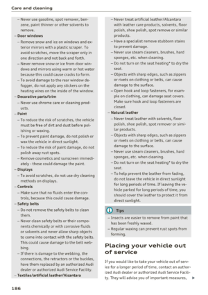 188
188 189
189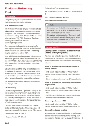 190
190 191
191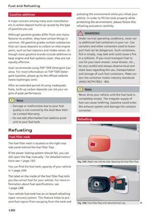 192
192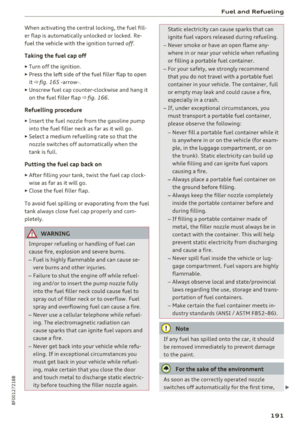 193
193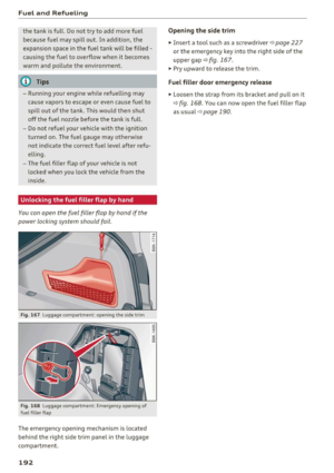 194
194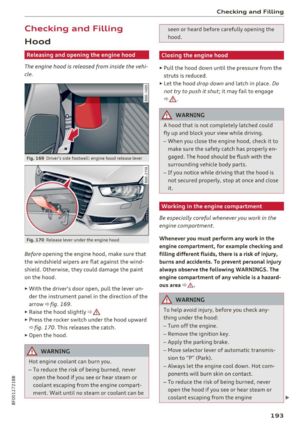 195
195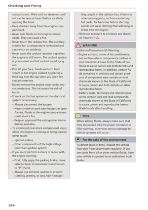 196
196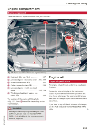 197
197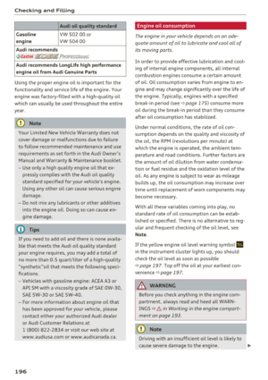 198
198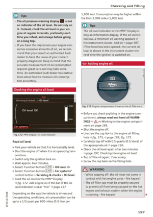 199
199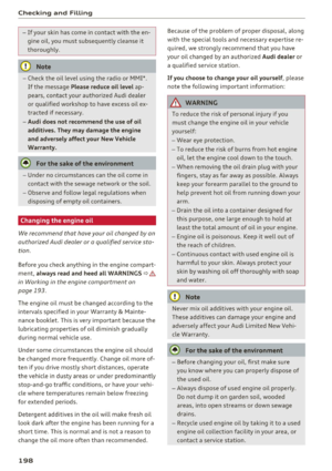 200
200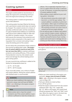 201
201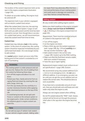 202
202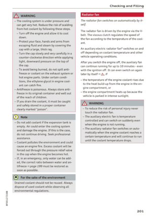 203
203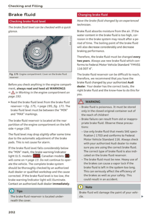 204
204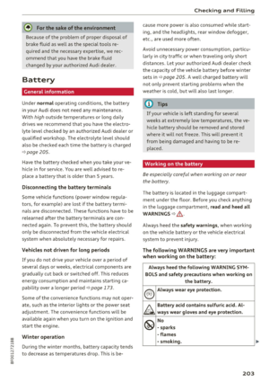 205
205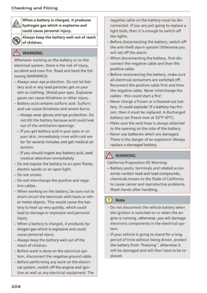 206
206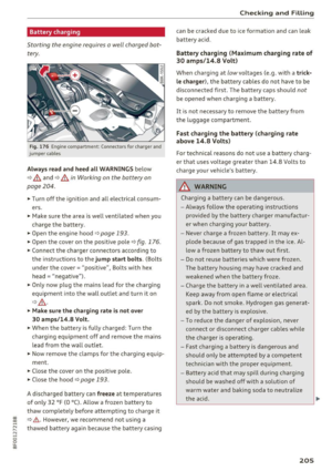 207
207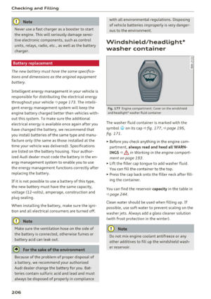 208
208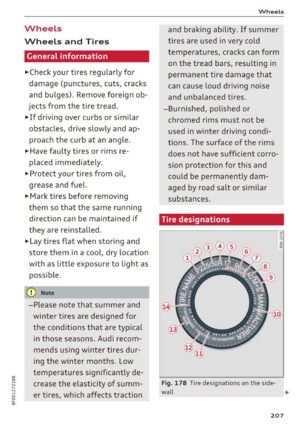 209
209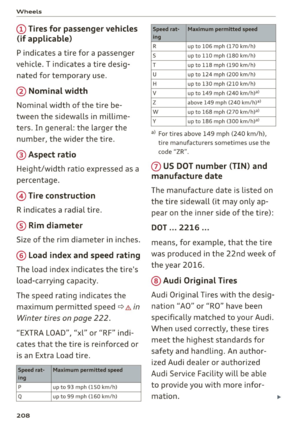 210
210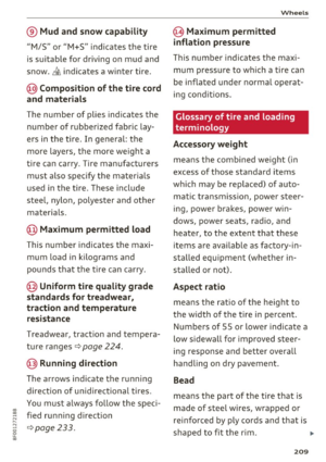 211
211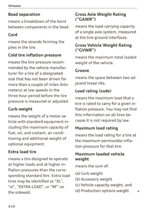 212
212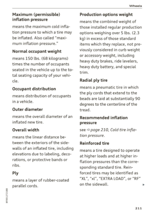 213
213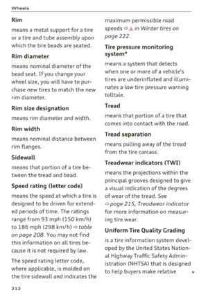 214
214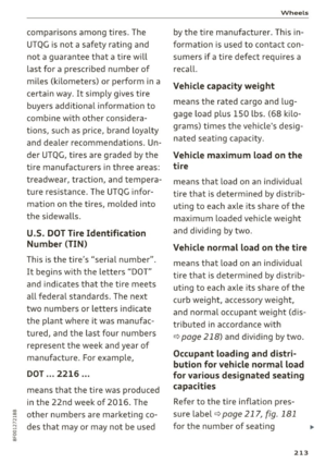 215
215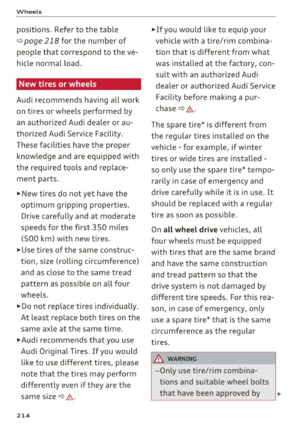 216
216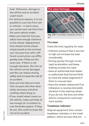 217
217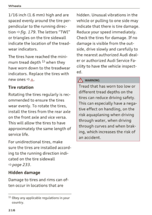 218
218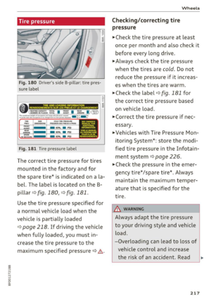 219
219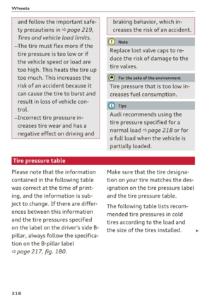 220
220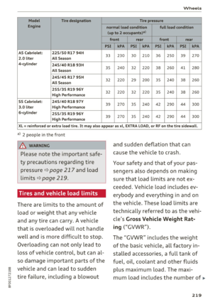 221
221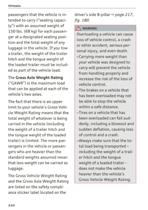 222
222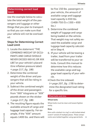 223
223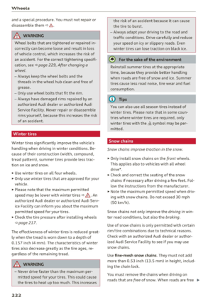 224
224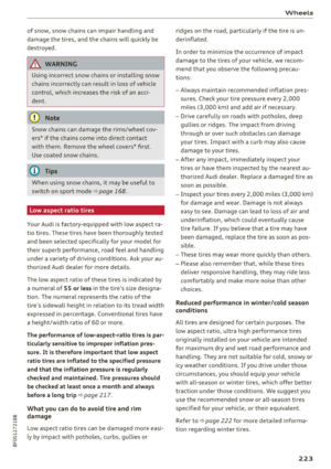 225
225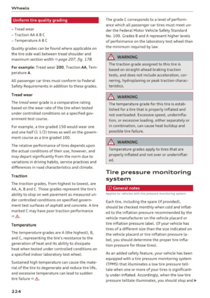 226
226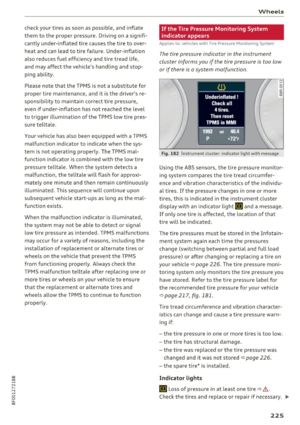 227
227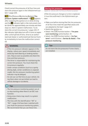 228
228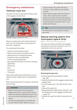 229
229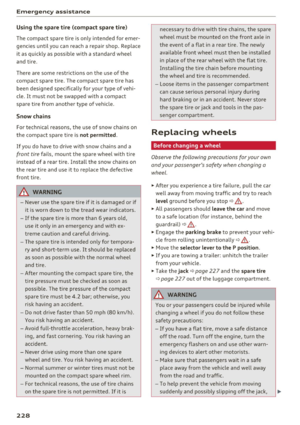 230
230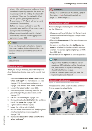 231
231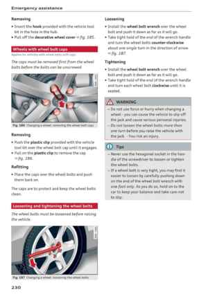 232
232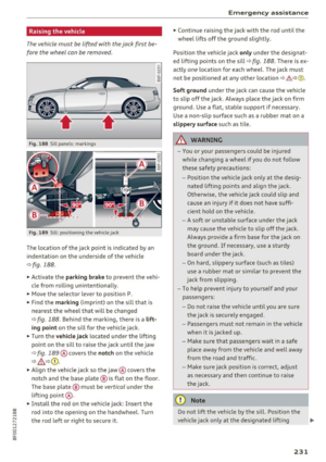 233
233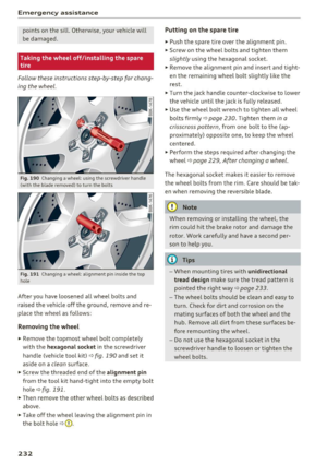 234
234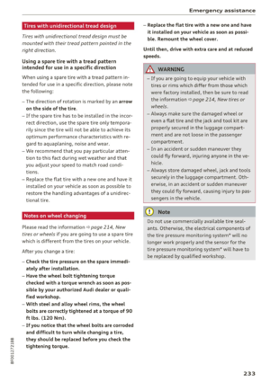 235
235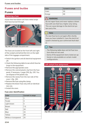 236
236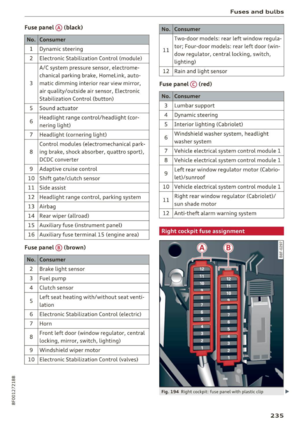 237
237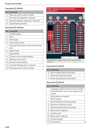 238
238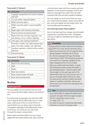 239
239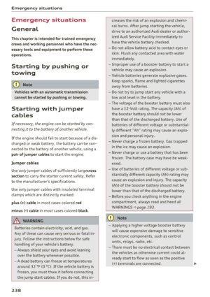 240
240 241
241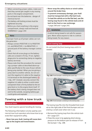 242
242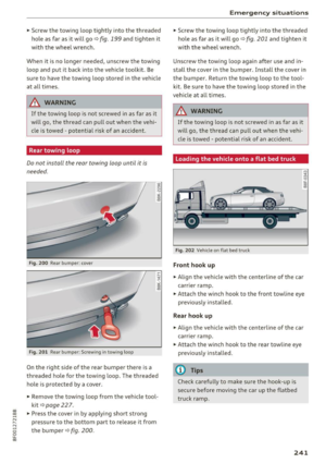 243
243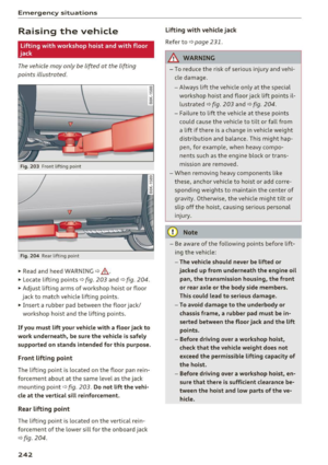 244
244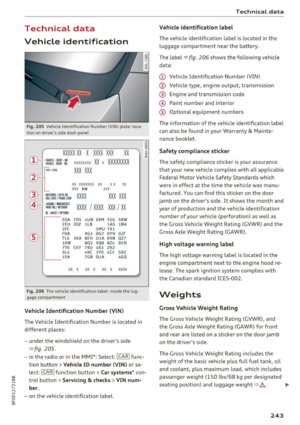 245
245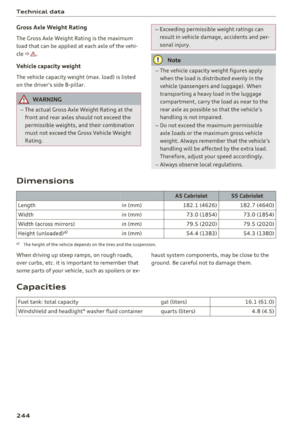 246
246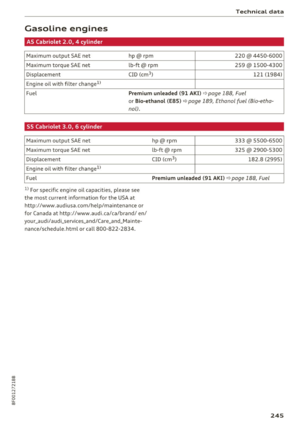 247
247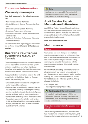 248
248 249
249 250
250 251
251 252
252 253
253 254
254 255
255 256
256 257
257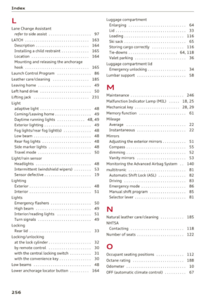 258
258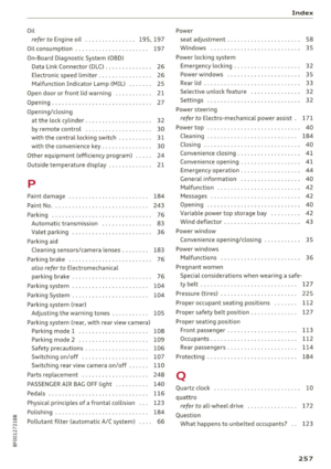 259
259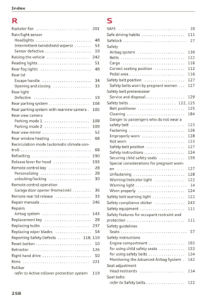 260
260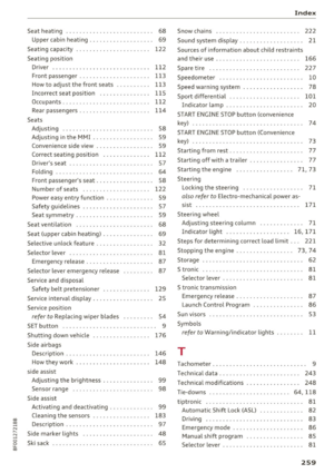 261
261 262
262 263
263 264
264 265
265