Page 57 of 112

Periodic maintenance an d a djustment
6-6
6
20 *Front fork • Check operation and for oil leak-
age. √√√√
21 *Shock a
bsor ber as-
sem bly • Check operation and shock ab-
sorber for oil leakage. √√√√
22 *Rear suspension re-
lay arm an
d con-
nectin g arm
pivotin g points • Check operation.
√√√√
23 En gine oil • Change.
• Check oil level and vehicle for oil
leakage. √√√√√√
24 En
gine oil filter car-
tri dg e •Replace.
√√√
25 *Coolin g system • Check coolant level and vehicle
for coolant leakage. √√√√√
• Change coolant. Every 3 years
26 *Front an
d rear
b rake switches • Check operation.
√√√√√√
27 Movin
g parts an d
ca bles • Lubricate.
√√√√√
28 *Throttle g rip • Check operation.
• Check throttle grip free play, and
adjust if necessary.
• Lubricate cable and grip housing. √√√√√
29 *Li
ghts, si gnals an d
switches • Check operation.
• Adjust headlight beam.
√√√√√√
NO. ITEM CHECK OR MAINTENANCE JOB
OD
OM ETER READING
ANNUAL
CHECK
1000 km
(600 mi) 10000 km
(6000 mi) 20000 km
(12000 mi) 30000 km
(18000 mi) 40000 km
(24000 mi)
U2CXE2E0.book Page 6 Tuesday, June 9, 2015 5:04 PM
Page 58 of 112
Periodic maintenance an d a djustment
6-7
6
EAU18681
TIP Air filter
• This model’s air filter is equipped with a disposable oil-coated paper element, which must not be cleaned with com- pressed air to avoid damaging it.
• The air filter element needs to be replaced more frequently when riding in unusually wet or dusty areas.
Hydraulic brake service
• Regularly check and, if necessary, correct the brake fluid level.
• Every two years replace the internal components of the brake master cylinders and calipers, and change the brake fluid.
• Replace the brake hoses every four years and if cracked or damaged.
U2CXE2E0.book Page 7 Tuesday, June 9, 2015 5:04 PM
Page 59 of 112
Periodic maintenance an d a djustment
6-8
6
EAU18713
Removin g an d installin g cowl-
in gs an d panelsThe cowlings and panels shown need
to be removed to perform some of the
maintenance jobs described in this
chapter. Refer to this section each time
a cowling or panel needs to be re-
moved and installed.
EAU55910
Cowlin gs A an d B
To remove a cowling1. Remove the bolts, quick fasten- ers, and quick fastener screw.
1. Cowling A
1. Cowling B
2. Cowling C
1. Panel A
2. Panel B
2
1
1. Cowling A
2. Bolt
3. Quick fastener
2 3
1 2
2
2
U2CXE2E0.book Page 8 Tuesday, June 9, 2015 5:04 PM
Page 60 of 112
Periodic maintenance an d a djustment
6-9
6 2. Remove the projection on cowling
A from the hole in cowling B as
shown.
1. Quick fastener
1. Quick fastener
2. Quick fastener screw
1. Cowling B
2. Bolt
3. Quick fastener
1. Quick fastener
1. Quick fastener
2. Quick fastener screw
1. Cowling A
2. Cowling B
U2CXE2E0.book Page 9 Tuesday, June 9, 2015 5:04 PM
Page 61 of 112
Periodic maintenance an d a djustment
6-10
6
3. Remove the forward-most projec-
tion from the slot, slide the cowling
forward, and then remove the re-
maining projections from the slots
as shown.
4. Disconnect the turn signal light lead coupler.
To install a cowling
1. Connect the turn signal light leadcoupler.
2. Fit the projections into the slots, slide the cowling rearward, and
then fit the forward-most projec-
tion into the slot.
3. Fit the projection on cowling A intothe hole in cowling B as shown.
1. Cowling A
2. Turn signal light lead coupler
1. Cowling B
2. Turn signal light lead coupler
1. Cowling A
2. Turn signal light lead coupler
1. Cowling B
2. Turn signal light lead coupler
U2CXE2E0.book Page 10 Tuesday, June 9, 2015 5:04 PM
Page 62 of 112
Periodic maintenance an d a djustment
6-11
6 4. Install the bolts, quick fasteners,
and quick fastener screw.
Cowlin g C
To remove the cowling
1. Remove cowling B and panel B. (See page 6-11.)
2. Unfasten the wire harness by pressing on the projection to open
the plastic fastener. 3. Remove the bolts and the quick
fastener, and then pull the cowling
off as shown. To install the cowling
1. Fit the slot in cowling C over the
projection on the front cowling.
2. Install the bolts and the quick fas- tener.
3. Place the wire harness in the orig- inal position, and then close the
plastic fastener.
4. Install the cowling and the panel.
EAU39063
Panels A an d B
To remove a panelRemove the bolts, and then pull the
panel off as shown.
1. Cowling A
2. Cowling B
1. Plastic fastener
2. Projection
3. Wire harness
1. Cowling C
2. Bolt
3. Quick fastener
1. Cowling C
2. Slot
3. Front cowling
4. Projection
U2CXE2E0.book Page 11 Tuesday, June 9, 2015 5:04 PM
Page 63 of 112

Periodic maintenance an d a djustment
6-12
6
To install a panel
Place the panel in the original position,
and then install the bolts.
EAU19653
Checkin
g the spark plug sThe spark plugs are important engine
components, which should be
checked periodically, preferably by a
Yamaha dealer. Since heat and depos-
its will cause any spark plug to slowly
erode, they should be removed and
checked in accordance with the peri-
odic maintenance and lubrication
chart. In addition, the condition of the
spark plugs can reveal the condition of
the engine.
The porcelain insulator around the
center electrode of each spark plug
should be a medium-to-light tan (the
ideal color when the vehicle is ridden
normally), and all spark plugs installed
in the engine should have the same
color. If any spark plug shows a dis-
tinctly different color, the engine could
be operating improperly. Do not at-
tempt to diagnose such problems
yourself. Instead, have a Yamaha deal-
er check the vehicle.
If a spark plug shows signs of elec-
trode erosion and excessive carbon or
other deposits, it should be replaced. Before installing a spark plug, the
spark plug gap should be measured
with a wire thickness gauge and, if
necessary, adjusted to specification.
Clean the surface of the spark plug
gasket and its mating surface, and
then wipe off any grime from the spark
plug threads.
1. Panel B
2. Bolt
Specified
spark plu g:
NGK/CR10EK
1. Spark plug gap
Spark plu g g ap:
0.6–0.7 mm (0.024–0.028 in)
Ti ghtenin g torque:
Spark plug: 13 Nm (1.3 m·kgf, 9.4 ft·lbf)
1
1
U2CXE2E0.book Page 12 Tuesday, June 9, 2015 5:04 PM
Page 64 of 112

Periodic maintenance an d a djustment
6-13
6
TIPIf a torque wrench is not available
when installing a spark plug, a good
estimate of the correct torque is 1/4–
1/2 turn past finger tight. However, the
spark plug should be tightened to the
specified torque as soon as possible.NOTICE
ECA10841
Do not use any tools to remove or in-
stall the spark plu g cap, otherwise
the i gnition coil coupler may get
d amag ed . The spark plu g cap may
b e difficult to remove b ecause the
ru bber seal on the en d of the cap fits
ti g htly. To remove the spark plu g
cap, simply twist it b ack and forth
while pullin g it out; to install it, twist
it back an d forth while pushin g it in.
EAU3899E
En gine oil an d oil filter car-
tri dgeThe engine oil level should be checked
before each ride. In addition, the oil
must be changed and the oil filter car-
tridge replaced at the intervals speci-
fied in the periodic maintenance and
lubrication chart.
To check the en gine oil level
1. Place the vehicle on a level surfa- ce and hold it in an upright posi-
tion. A slight tilt to the side can
result in a false reading.
2. Start the engine, warm it up for several minutes, and then turn it
off.
3. Wait a few minutes until the oil set- tles.
4. Remove the engine oil dipstick and wipe it clean, insert it back
into the hole (without screwing it
in), and then remove it again to
check the oil level.TIPThe engine oil should be between the
minimum and maximum level marks.
5. If the engine oil is at or below theminimum level mark, remove the
engine oil filler cap, and then add
sufficient oil of the recommended
type to raise it to the correct level.1. Engine oil dipstick
2. Maximum level mark
3. Minimum level mark
1. Engine oil filler cap
U2CXE2E0.book Page 13 Tuesday, June 9, 2015 5:04 PM
 1
1 2
2 3
3 4
4 5
5 6
6 7
7 8
8 9
9 10
10 11
11 12
12 13
13 14
14 15
15 16
16 17
17 18
18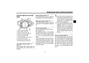 19
19 20
20 21
21 22
22 23
23 24
24 25
25 26
26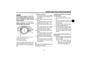 27
27 28
28 29
29 30
30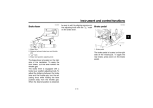 31
31 32
32 33
33 34
34 35
35 36
36 37
37 38
38 39
39 40
40 41
41 42
42 43
43 44
44 45
45 46
46 47
47 48
48 49
49 50
50 51
51 52
52 53
53 54
54 55
55 56
56 57
57 58
58 59
59 60
60 61
61 62
62 63
63 64
64 65
65 66
66 67
67 68
68 69
69 70
70 71
71 72
72 73
73 74
74 75
75 76
76 77
77 78
78 79
79 80
80 81
81 82
82 83
83 84
84 85
85 86
86 87
87 88
88 89
89 90
90 91
91 92
92 93
93 94
94 95
95 96
96 97
97 98
98 99
99 100
100 101
101 102
102 103
103 104
104 105
105 106
106 107
107 108
108 109
109 110
110 111
111


2. Unfa")