Page 41 of 112
To increase the compression damping
force and thereby harden the com-
pression damping, turn the adjusti")
Instrument and control functions
3-26
3
Compression damping force (for slow
compression damping)To increase the compression damping
force and thereby harden the com-
pression damping, turn the adjusting
screw in direction (a). To decrease the
compression damping force and there-
by soften the compression damping,
turn the adjusting screw in direction (b).
TIPTo obtain a precise adjustment, it is
advisable to check the actual total
number of clicks or turns of each
damping force adjusting mechanism. This adjustment range may not exactly
match the specifications listed due to
small differences in production.
WARNING
EWA10222
This shock a
bsor ber assem bly con-
tains hig hly pressurize d nitro gen
g as. Rea d an d un derstan d the fol-
lowin g information before han dlin g
the shock a bsor ber assem bly.
Do not tamper with or attempt
to open the cylind er assembly.
Do not su bject the shock a b-
sor ber assem bly to an open
flame or other hi gh heat source.
This may cause the unit to ex-
plo de due to excessive gas
pressure.
Do not deform or damag e the
cylin der in any way. Cylin der
d ama ge will result in poor
d ampin g performance.
Do not dispose of a d amaged or
worn-out shock a bsor ber as-
sem bly y
ourself. Take the shock
a b sor ber assem bly to a Yamaha
d ealer for any service.
Compression dampin g setting (for
fast compression dampin g):
Minimum (soft): 5.5 turn(s) in direction (b)*
Standard: 3 turn(s) in direction (b)*
Maximum (hard):
0 turn(s) in direction (b)*
* With the adjusting bolt fully turned in direction (a)
1. Compression damping force adjusting
screw (for slow compression damping)
Compression dampin g setting (for
slow compression dampin g):
Minimum (soft):
18 click(s) in direction (b)*
Standard: 16 click(s) in direction (b)*
Maximum (hard): 1 click(s) in direction (b)*
* With the adjusting bolt fully turned
in direction (a)
1
(a)
(b)
U2CXE2E0.book Page 26 Tuesday, June 9, 2015 5:04 PM
Page 42 of 112

Instrument and control functions
3-27
3
EAU38963
Lugga ge strap hol dersThere are six luggage strap holders,
four on the bottom of the passenger
seat and one on each passenger foot-
rest. To use the luggage strap holders on the passenger seat, remove the
passenger seat. (See page 3-20.) Un-
hook the straps from the hooks, and
then install the seat with the straps
hanging out from under the passenger
seat.
EAU41942
EXUP systemThis model is equipped with Yamaha’s
EXUP (EXhaust Ultimate Power valve)
system. This system boosts engine
power by means of a valve that regu-
lates the inner diameter of the exhaust
pipe. The EXUP system valve is con-
stantly adjusted in accordance with the
engine speed by a computer-con-
trolled servomotor.NOTICE
ECA15611
The EXUP system has
been set an d
extensively teste d at the Yamaha
factory. Chan gin g these settin gs
without sufficient technical knowl-
e dge may result in poor perfor-
mance of or damag e to the eng ine.
1. Luggage strap holder
2. Hook
1. Luggage strap holder
2 1
1
2
U2CXE2E0.book Page 27 Tuesday, June 9, 2015 5:04 PM
Page 43 of 112

Instrument and control functions
3-28
3
EAU15306
Si destan dThe sidestand is located on the left
side of the frame. Raise the sidestand
or lower it with your foot while holding
the vehicle upright.TIPThe built-in sidestand switch is part of
the ignition circuit cut-off system,
which cuts the ignition in certain situa-
tions. (See the following section for an
explanation of the ignition circuit cut-
off system.)
WARNING
EWA10242
The vehicle must not b e ridden with
the si destan d d own, or if the si de-
stan d cannot b e properly move d up
(or does not stay up), otherwise the
si destan d coul d contact the g round
an d d istract the operator, resultin g
in a possi ble loss of control.
Yamaha’s i gnition circuit cut-off
system has been desi gne d to assist
the operator in fulfilling the respon-
si bility of raisin g the si destan d b e-
fore startin g off. Therefore, check this system re
gularly an d have a
Yamaha dealer repair it if it does not
function properly.
EAU44893
I g nition circuit cut-off systemThe ignition circuit cut-off system
(comprising the sidestand switch,
clutch switch and neutral switch) has
the following functions.
It prevents starting when the
transmission is in gear and the
sidestand is up, but the clutch le-
ver is not pulled.
It prevents starting when the
transmission is in gear and the
clutch lever is pulled, but the side-
stand is still down.
It cuts the running engine when
the transmission is in gear and the
sidestand is moved down.
Periodically check the operation of the
ignition circuit cut-off system accord-
ing to the following procedure.
U2CXE2E0.book Page 28 Tuesday, June 9, 2015 5:04 PM
Page 44 of 112

Instrument and control functions
3-29
3
With the engine turned off:
1. Move the sidestand down.
2. Make sure that the engine stop switch is set to “
3. Turn the key on.
4. Shift the transmission into the neutral position.
5. Push the start switch.
Does the engine start?
With the engine still running:
6. Move the sidestand up.
7. Keep the clutch lever pulled.
8. Shift the transmission into gear.
9. Move the sidestand down.
Does the engine stall?
After the engine has stalled:
10. Move the sidestand up.
11. Keep the clutch lever pulled.
12. Push the start switch.
Does the engine start?
The system is OK. The motorcycle can be ridden. The neutral switch may not be working correctly.
The motorcycle should not be ridden
until
checked by a Yamaha dealer.
The sidestand switch may not be working correctly.
The motorcycle should not be ridden until
checked by a Yamaha dealer.
The clutch switch may not be working correctly.
The motorcycle should not be ridden until
checked by a Yamaha dealer.
YES NO YES NO YES NO
If a malfunction is noted, have a Yamaha
dealer check the system before riding.
WARNING
”.
U2CXE2E0.book Page 29 Tuesday, June 9, 2015 5:04 PM
Page 45 of 112

For your safety – pre-operation checks
4-1
4
EAU15599
Inspect your vehicle each time you use it to make sure the vehicle is in safe operating condition. Always follow the inspection
and maintenance procedures and schedules described in the Owner’s Manual.
WARNING
EWA11152
Failure to inspect or maintain the vehicle properly increases the possibility of an accident or equipment d amage.
Do not operate the vehicle if you fin d any pro blem. If a pro blem cannot b e corrected b y the proce dures provi ded in
this manual, have the vehicle inspecte d b y a Yamaha dealer.Before using this vehicle, check the following points:
ITEM CHECKS PAGE
Fuel • Check fuel level in fuel tank.
• Refuel if necessary.
• Check fuel line for leakage.
• Check fuel tank breather hose and overflow hose for obstructions, cracks or
damage, and check hose connections. 3-17, 3-19
En gine oil • Check oil level in engine.
• If necessary, add recommended oil to specified level.
• Check vehicle for oil leakage. 6-13
Coolant • Check coolant level in reservoir.
• If necessary, add recommended coolant to specified level.
• Check cooling system for leakage. 6-16
Front brake • Check operation.
• If soft or spongy, have Yamaha dealer bleed hydraulic system.
• Check brake pads for wear.
• Replace if necessary.
• Check fluid level in reservoir.
• If necessary, add specified brake fluid to specified level.
• Check hydraulic system for leakage. 6-25, 6-25
U2CXE2E0.book Page 1 Tuesday, June 9, 2015 5:04 PM
Page 46 of 112

For your safety – pre-operation checks
4-2
4
Rear brake • Check operation.
• If soft or spongy, have Yamaha dealer bleed hydraulic system.
• Check brake pads for wear.
• Replace if necessary.
• Check fluid level in reservoir.
• If necessary, add specified brake fluid to specified level.
• Check hydraulic system for leakage. 6-25, 6-25
Clutch • Check operation.
• Lubricate cable if necessary.
• Check lever free play.
• Adjust if necessary.
6-23
Throttle g rip • Make sure that operation is smooth.
• Check throttle grip free play.
• If necessary, have Yamaha dealer adjust throttle grip free play and lubricate ca-
ble and grip housing. 6-20, 6-30
Control ca bles • Make sure that operation is smooth.
• Lubricate if necessary. 6-29
Drive chain • Check chain slack.
• Adjust if necessary.
• Check chain condition.
• Lubricate if necessary.
6-27, 6-29
Wheels an d tires •Check for damage.
• Check tire condition and tread depth.
• Check air pressure.
• Correct if necessary.
6-20, 6-23
Brake an d shift pe dals • Make sure that operation is smooth.
• Lubricate pedal pivoting points if necessary. 6-30
Brake an d clutch levers • Make sure that operation is smooth.
• Lubricate lever pivoting points if necessary.
6-31
Si destan d • Make sure that operation is smooth.
• Lubricate pivot if necessary.
6-31
ITEM
CHECKS PAGE
U2CXE2E0.book Page 2 Tuesday, June 9, 2015 5:04 PM
Page 47 of 112
For your safety – pre-operation checks
4-3
4
Chassis fasteners• Make sure that all nuts, bolts and screws are properly tightened.
• Tighten if necessary. —
Instruments, li ghts, si gnals
an d switches • Check operation.
• Correct if necessary.
—
Si destan d switch • Check operation of ignition circuit cut-off system.
• If system is not working correctly, have Yamaha dealer check vehicle. 3-28
ITEM CHECKS PAGE
U2CXE2E0.book Page 3 Tuesday, June 9, 2015 5:04 PM
Page 48 of 112

Operation and important rid ing points
5-1
5
EAU15952
Read the Owner’s Manual carefully to
become familiar with all controls. If
there is a control or function you do not
understand, ask your Yamaha dealer.
WARNING
EWA10272
Failure to familiarize yourself with
the controls can lead to loss of con-
trol, which coul d cause an acci dent
or injury.
EAU47152
TIPThis model is equipped with: a lean angle sensor to stop the en-
gine in case of a turnover. In this
case, the display will indicate error
code 30, but this is not a malfunc-
tion. Turn the key to “OFF” and
then to “ON” to clear the error co-
d e . F ai l in g to do s o wi ll pr e v e nt the
engine from starting even though
the engine will crank when push-
ing the start switch.
an engine auto-stop system. The
engine stops automatically if left
idling for 20 minutes. In this case,
the display will indicate error code
70, but this is not a malfunction.
Push the start switch to clear the
error code and to restart the en-
gine.
EAU33016
Startin g the en gineIn order for the ignition circuit cut-off
system to enable starting, one of the
following conditions must be met:
The transmission is in the neutral
position.
The transmission is in gear with
the clutch lever pulled and the
sidestand up.
See page 3-28 for more informa-
tion.
1. Turn the key to “ON” and make sure that the engine stop switch is
set to “ ”.
The following warning lights and
indicator lights should come on for
a few seconds, then go off. Oil level warning light
Fuel level warning light
Coolant temperature warning
light
Shift timing indicator light
Engine trouble warning light
Immobilizer system indicator
light
U2CXE2E0.book Page 1 Tuesday, June 9, 2015 5:04 PM
 1
1 2
2 3
3 4
4 5
5 6
6 7
7 8
8 9
9 10
10 11
11 12
12 13
13 14
14 15
15 16
16 17
17 18
18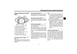 19
19 20
20 21
21 22
22 23
23 24
24 25
25 26
26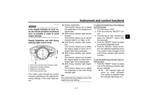 27
27 28
28 29
29 30
30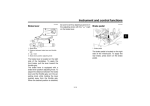 31
31 32
32 33
33 34
34 35
35 36
36 37
37 38
38 39
39 40
40 41
41 42
42 43
43 44
44 45
45 46
46 47
47 48
48 49
49 50
50 51
51 52
52 53
53 54
54 55
55 56
56 57
57 58
58 59
59 60
60 61
61 62
62 63
63 64
64 65
65 66
66 67
67 68
68 69
69 70
70 71
71 72
72 73
73 74
74 75
75 76
76 77
77 78
78 79
79 80
80 81
81 82
82 83
83 84
84 85
85 86
86 87
87 88
88 89
89 90
90 91
91 92
92 93
93 94
94 95
95 96
96 97
97 98
98 99
99 100
100 101
101 102
102 103
103 104
104 105
105 106
106 107
107 108
108 109
109 110
110 111
111