Page 73 of 112

Periodic maintenance an d a djustment
6-22
6
Tire information
This model is equipped with tubeless
tires and tire air valves.
Tires age, even if they have not been
used or have only been used occasion-
ally. Cracking of the tread and sidewall
rubber, sometimes accompanied by
carcass deformation, is an evidence of
ageing. Old and aged tires shall be
checked by tire specialists to ascertain
their suitability for further use.
WARNING
EWA10482
The front an d rear tires shoul d
b e of the same make an d d e-
si gn, otherwise the han dlin g characteristics of the motorcy-
cle may b
e different, which
coul d lea d to an acci dent.
Always make sure that the valve
caps are securely installe d to
prevent air pressure leaka ge.
Use only the tire valves an d
valve cores liste d below to
avoi d tire deflation during a
hi gh-spee d ri de.
After extensive tests, only the tires list-
ed below have been approved for this
model by Yamaha.
WARNING
EWA10601
This motorcycle is fitte d with super-
hi gh-spee d tires. Note the followin g
points in or der to make the most ef-
ficient use of these tires. Use only the specified replace-
ment tires. Other tires may run
the dan ger of bursting at super
hi gh spee ds.
Bran d-new tires can have a rel-
atively poor grip on certain roa d
surfaces until they have been
“ b roken in”. Therefore, it is a d-
visa ble before doin g any hi gh-
speed ridin g to ri de conserva-
tively for approximately 100 km
(60 mi) after installin g a new tire.
The tires must be warmed up
b efore a hi gh-spee d run.
Always a djust the tire air pres-
sure accor din g to the operatin g
con ditions.
1. Tire air valve
2. Tire air valve core
3. Tire air valve cap with seal
Front tire:
Size:120/70 ZR17M/C (58W)
Manufacturer/model: BRIDGESTONE/BT016FF
DUNLOP/Qualifier PTM
Rear tire: Size:180/55 ZR17M/C (73W)
Manufacturer/model: BRIDGESTONE/BT016RF
DUNLOP/Qualifier PTM
FRONT an d REAR:
Tire air valve: TR412
Valve core: #9100 (original)
U2CXE2E0.book Page 22 Tuesday, June 9, 2015 5:04 PM
Page 74 of 112

Periodic maintenance an d a djustment
6-23
6
EAU21963
Cast wheelsTo maximize the performance, durabil-
ity, and safe operation of your vehicle,
note the following points regarding the
specified wheels.
The wheel rims should be
checked for cracks, bends, warp-
age or other damage before each
ride. If any damage is found, have
a Yamaha dealer replace the
wheel. Do not attempt even the
smallest repair to the wheel. A de-
formed or cracked wheel must be
replaced.
The wheel should be balanced
whenever either the tire or wheel
has been changed or replaced. An
unbalanced wheel can result in
poor performance, adverse han-
dling characteristics, and a short-
ened tire life.
EAU33892
Adjustin g the clutch lever free
playThe clutch lever free play should mea-
sure 10.0–15.0 mm (0.39–0.59 in) as
shown. Periodically check the clutch
lever free play and, if necessary, adjust
it as follows.
To increase the clutch lever free play,
turn the clutch lever free play adjusting
bolt at the clutch lever in direction (a).
To decrease the clutch lever free play,
turn the adjusting bolt in direction (b).
TIPIf the specified clutch lever free play
cannot be obtained as described
above, proceed as follows.1. Fully turn the adjusting bolt at the
clutch lever in direction (a) to loos-
en the clutch cable.
2. Loosen the locknut at the crank- case.
3. To increase the clutch lever free play, turn the clutch lever free play
adjusting nut in direction (a). To
decrease the clutch lever free
play, turn the adjusting nut in di-
rection (b).
4. Tighten the locknut.
1. Clutch lever free play adjusting bolt
2. Clutch lever free play
1. Locknut
2. Clutch lever free play adjusting nut
U2CXE2E0.book Page 23 Tuesday, June 9, 2015 5:04 PM
Page 75 of 112

Periodic maintenance an d a djustment
6-24
6
EAU37914
Checkin g the brake lever free
playThere should be no free play at the
brake lever end. If there is free play,
have a Yamaha dealer inspect the
brake system.
WARNING
EWA14212
A soft or spon gy feelin g in the brake
lever can in dicate the presence of
air in the hy draulic system. If there is
air in the hy draulic system, have a
Yamaha dealer blee d the system be-
fore operatin g the vehicle. Air in the
hy draulic system will diminish the b
rakin g performance, which may re-
sult in loss of control an d an acci-
d ent.
EAU22274
Brake li ght switchesThe brake light, which is activated by
the brake pedal and brake lever,
should come on just before braking
takes effect. If necessary, adjust the
rear brake light switch as follows, but
the front brake light switch should be
adjusted by a Yamaha dealer.
Turn the rear brake light switch adjust-
ing nut while holding the rear brake
light switch in place. To make the
brake light come on earlier, turn the ad-
justing nut in direction (a). To make the
brake light come on later, turn the ad-
justing nut in direction (b).
1. No brake lever free play
1
1. Rear brake light switch
2. Rear brake light switch adjusting nut
2
(b)
(a)
1
U2CXE2E0.book Page 24 Tuesday, June 9, 2015 5:04 PM
Page 76 of 112

Periodic maintenance an d a djustment
6-25
6
EAU22393
Checkin g the front an d rear
b rake pa dsThe front and rear brake pads must be
checked for wear at the intervals spec-
ified in the periodic maintenance and
lubrication chart.
EAU36891
Front brake pa ds
Each front brake pad is provided with
wear indicators, which allows you to
check the brake pad wear without hav-
ing to disassemble the brake. To check
the brake pad wear, check the position
of the wear indicators while applying
the brake. If a brake pad has worn to
the point that a wear indicator almost touches the brake disc, have a
Yamaha dealer replace the brake pads as a set.
EAU46292
Rear brake pad s
Each rear brake pad is provided with
wear indicator grooves, which allow
you to check the brake pad wear with-
out having to disassemble the brake.
To check the brake pad wear, check
the wear indicator grooves. If a brake
pad has worn to the point that a wear
indicator groove almost appears, have
a Yamaha dealer replace the brake
pads as a set.
EAU22582
Checkin g the brake flui d levelBefore riding, check that the brake fluid
is above the minimum level mark.
Check the brake fluid level with the top
of the reservoir level. Replenish the
brake fluid if necessary.
Front brake
1. Brake pad wear indicator
1. Brake pad wear indicator groove
1
1
1. Minimum level mark
U2CXE2E0.book Page 25 Tuesday, June 9, 2015 5:04 PM
Page 77 of 112

Periodic maintenance an d a djustment
6-26
6
Rear
brake
WARNING
EWA15991
Improper maintenance can result in
loss of b raking a bility. O bserve
these precautions: Insufficient brake flui d may al-
low air to enter the brake sys-
tem, re ducin g brakin g
performance.
Clean the filler cap before re-
movin g. Use only DOT 4 brake
flui d from a seale d container.
Use only the specified b rake flu-
i d ; otherwise, the ru bber seals
may deteriorate, causin g leak-
a g e.
Refill with the same type of
brake flui d. A dding a brake fluid
other than DOT 4 may result in a
harmful chemical reaction.
Be careful that water d oes not
enter the brake flui d reservoir
when refillin g. Water will sig nifi-
cantly lower the boilin g point of
the flui d an d may result in vapor
lock.
NOTICE
ECA17641
Brake flui d may d amage painte d
surfaces or plastic parts. Always
clean up spilled fluid imme diately.As the brake pads wear, it is normal for
the brake fluid level to gradually go
down. A low brake fluid level may indi-
cate worn brake pads and/or brake
system leakage; therefore, be sure to
check the brake pads for wear and the
brake system for leakage. If the brake fluid level goes down suddenly, have a
Yamaha dealer check the cause before
further riding.
1. Minimum level markSpecifie
d b rake flui d:
DOT 4
U2CXE2E0.book Page 26 Tuesday, June 9, 2015 5:04 PM
Page 78 of 112

Periodic maintenance an d a djustment
6-27
6
EAU22733
Chan gin g the brake flui dHave a Yamaha dealer change the
brake fluid at the intervals specified in
the periodic maintenance and lubrica-
tion chart. In addition, have the oil seals
of the master cylinders and calipers as
well as the brake hoses replaced at the
intervals listed below or whenever they
are damaged or leaking.
Oil seals: Replace every two
years.
Brake hoses: Replace every four
years.
EAU22762
Drive chain slackThe drive chain slack should be
checked before each ride and adjusted
if necessary.
EAU22777
To check the d rive chain slack
1. Place the motorcycle on the side- stand.TIPWhen checking and adjusting the drive
chain slack, there should be no weight
on the motorcycle.2. Shift the transmission into theneutral position.
3. Measure the drive chain slack as shown. 4. If the drive chain slack is incorrect,
adjust it as follows.
EAU39057
To a djust the drive chain slack
Consult a Yamaha dealer before ad-
justing the drive chain slack. 1. Loosen the axle nut and the lock- nut on each side of the swingarm.
Drive chain slack:30.0–45.0 mm (1.18–1.77 in)
1. Drive chain slack
U2CXE2E0.book Page 27 Tuesday, June 9, 2015 5:04 PM
Page 79 of 112
. To loosen the drive
chain, turn t")
Periodic maintenance an d a djustment
6-28
6
2. To tighten the drive chain, turn the drive chain slack adjusting bolt on
each side of the swingarm in di-
rection (a). To loosen the drive
chain, turn the adjusting bolt on
each side of the swingarm in di-
rection (b), and then push the rear
wheel forward. NOTICE: Improp-
er drive chain slack will over-
loa d the en gine as well as other
vital parts of the motorcycle and
can lead to chain slippa ge or
b reakag e. To prevent this from occurrin
g, keep the d rive chain
slack within the specified limits.
[ECA10572]
TIPUsing the alignment marks on each
drive chain puller, make sure that both
chain pullers are in the same position
for proper wheel alignment. Use the
end of the swingarm as the reference
point for the alignment marks.3. Tighten the axle nut to the speci-
fied torque. 4. Tighten the adjusting bolts in di-
rection (a) to their specified
torque.
5. Tighten the locknuts to their spec- ified torque.
6. Make sure that the drive chain pullers are in the same position,
the drive chain slack is correct,
and the drive chain moves
smoothly.
1. Drive chain slack adjusting bolt
2. Locknut
3. Alignment marks
4. Axle nut
5. Drive chain puller
45
1
2
3
1. Drive chain slack adjusting bolt
2. Locknut
Tightenin g torque:
Axle nut: 110 Nm (11 m·kgf, 80 ft·lbf)
(a)
(b)
12
Tightenin g torque:
Drive chain slack adjusting bolt: 2.0 Nm (0.20 m·kgf, 1.4 ft·lbf)
Ti ghtenin g torque:
Locknut: 16 Nm (1.6 m·kgf, 12 ft·lbf)
U2CXE2E0.book Page 28 Tuesday, June 9, 2015 5:04 PM
Page 80 of 112

Periodic maintenance an d a djustment
6-29
6
EAU23026
Cleanin g an d lu bricatin g the
d rive chainThe drive chain must be cleaned and
lubricated at the intervals specified in
the periodic maintenance and lubrica-
tion chart, otherwise it will quickly wear
out, especially when riding in dusty or
wet areas. Service the drive chain as
follows.NOTICE
ECA10584
The drive chain must b e lubricated
after washin g the motorcycle, ri din g
in the rain or ri din g in wet areas.1. Clean the drive chain with kero-
sene and a small soft brush.
NOTICE: To prevent d amaging
the O-rin gs, do not clean the
d rive chain with steam cleaners,
hi gh-pressure washers or inap-
propriate solvents.
[ECA11122]
2. Wipe the drive chain dry.
3. Thoroughly lubricate the drive chain with a special O-ring chain
lubricant. NOTICE: Do not use
en gine oil or any other lu bri-
cants for the drive chain, as they may contain su
bstances that
coul d damag e the O-rin gs.
[ECA11112] EAU23098
Checkin
g an d lu bricatin g the
cab lesThe operation of all control cables and
the condition of the cables should be
checked before each ride, and the ca-
bles and cable ends should be lubri-
cated if necessary. If a cable is
damaged or does not move smoothly,
have a Yamaha dealer check or re-
place it. WARNING! Dama ge to the
outer housin g of cab les may result
in internal rustin g an d cause inter-
ference with cab le movement. Re-
place damag ed cab les as soon as
possi ble to prevent unsafe con di-
tions.
[EWA10712]
Recommen ded lu bricant:
Yamaha cable lubricant or other
suitable cable lubricant
U2CXE2E0.book Page 29 Tuesday, June 9, 2015 5:04 PM
 1
1 2
2 3
3 4
4 5
5 6
6 7
7 8
8 9
9 10
10 11
11 12
12 13
13 14
14 15
15 16
16 17
17 18
18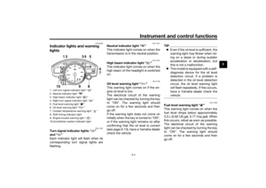 19
19 20
20 21
21 22
22 23
23 24
24 25
25 26
26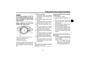 27
27 28
28 29
29 30
30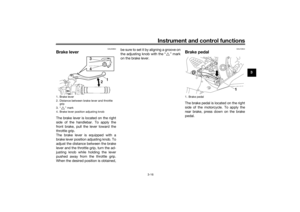 31
31 32
32 33
33 34
34 35
35 36
36 37
37 38
38 39
39 40
40 41
41 42
42 43
43 44
44 45
45 46
46 47
47 48
48 49
49 50
50 51
51 52
52 53
53 54
54 55
55 56
56 57
57 58
58 59
59 60
60 61
61 62
62 63
63 64
64 65
65 66
66 67
67 68
68 69
69 70
70 71
71 72
72 73
73 74
74 75
75 76
76 77
77 78
78 79
79 80
80 81
81 82
82 83
83 84
84 85
85 86
86 87
87 88
88 89
89 90
90 91
91 92
92 93
93 94
94 95
95 96
96 97
97 98
98 99
99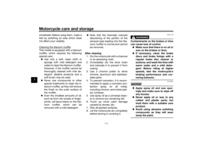 100
100 101
101 102
102 103
103 104
104 105
105 106
106 107
107 108
108 109
109 110
110 111
111