Page 17 of 112

Instrument and control functions
3-2
3
Keep other immo bilizer system
keys away from the main switch
as they may cause si gnal inter-
ference.
EAU10474
Main switch/steerin g lockThe main switch/steering lock controls
the ignition and lighting systems, and is
used to lock the steering. The various
positions are described below.TIPBe sure to use the standard key (black
bow) for regular use of the vehicle. To
minimize the risk of losing the code re-
registering key (red bow), keep it in a
safe place and only use it for code re-
registering.
EAU38531
ON
All electrical circuits are supplied with
power; the meter lighting, taillight, li-
cense plate light and auxiliary light
come on, and the engine can be start-
ed. The key cannot be removed.TIPThe headlight comes on automatically
when the engine is started and stays
on until the key is turned to “OFF”,
even if the engine stalls.
EAU10662
OFF
All electrical systems are off. The key
can be removed.
WARNING
EWA10062
Never turn the key to “OFF” or
“LOCK” while the vehicle is movin g.
Otherwise the electrical systems will
b e switche d off, which may result in
loss of control or an acci dent.
P
ON
OFF
LOCK
U2CXE2E0.book Page 2 Tuesday, June 9, 2015 5:04 PM
Page 18 of 112

Instrument and control functions
3-3
3
EAU10686
LOCK
The steering is locked and all electrical
systems are off. The key can be re-
moved.
To lock the steering1. Turn the handlebars all the way to
the left.
2. With the key in the “OFF” position, push the key in and turn it to
“LOCK”.
3. Remove the key.
TIPIf the steering will not lock, try turning
the handlebars back to the right slight-
ly.To unlock the steering1. Insert the key.
2. With the key in the “LOCK” posi- tion, push the key in and turn it to
“OFF”.
EAU34342
(Parkin g)
The steering is locked, and the taillight,
license plate light and auxiliary light are
on. The hazard lights and turn signal lights can be turned on, but all other
electrical systems are off. The key can
be removed.
The steering must be locked before the
key can be turned to “ ”.
NOTICE
ECA11021
Do not use the parkin
g position for
an exten ded len gth of time, other-
wise the battery may d ischarge.
1. Push.
2. Turn.12
1. Push.
2. Turn.12
U2CXE2E0.book Page 3 Tuesday, June 9, 2015 5:04 PM
Page 19 of 112

Instrument and control functions
3-4
3
EAU49398
In dicator lig hts and warning
lig hts
EAU11032
Turn si gnal in dicator li ghts “ ”
an d“”
Each indicator light will flash when its
corresponding turn signal lights are
flashing.
EAU11061
Neutral in dicator li ght “ ”
This indicator light comes on when the
transmission is in the neutral position.
EAU11081
Hi gh beam in dicator li ght “ ”
This indicator light comes on when the
high beam of the headlight is switched
on.
EAU11256
Oil level warnin g lig ht “ ”
This warning light comes on if the en-
gine oil level is low.
The electrical circuit of the warning
light can be checked by turning the key
to “ON”. The warning light should
come on for a few seconds and then
go off.
If the warning light does not come on
initially when the key is turned to “ON”,
or if the warning light remains on after
confirming that the oil level is correct
(see page 6-13), have a Yamaha dealer
check the vehicle.
TIP Even if the oil level is sufficient, the
warning light may flicker when rid-
ing on a slope or during sudden
acceleration or deceleration, but
this is not a malfunction.
This model is equipped with a self-
diagnosis device for the oil level
detection circuit. If a problem is
detected in the oil level detection
circuit, the oil level warning light
will flash repeatedly. If this occurs,
have a Yamaha dealer check the
vehicle.
EAU11368
Fuel level warning light “ ”
This warning light comes on when the
fuel level drops below approximately
3.5 L (0.92 US gal, 0.77 Imp.gal). When
this occurs, refuel as soon as possible.
The electrical circuit of the warning
light can be checked by turning the key
to “ON”. The warning light should
come on for a few seconds and then
go off.
1. Left turn signal indicator light “ ”
2. Neutral indicator light “ ”
3. High beam indicator light “ ”
4. Right turn signal indicator light “ ”
5. Fuel level warning light “ ”
6. Oil level warning light “ ”
7. Coolant temperature warning light “ ”
8. Shift timing indicator light
9. Engine trouble warning light “ ”
10.Immobilizer system indicator light
km/h
TRIP A
˚C
12 34 5
6
7
8
9
10
U2CXE2E0.book Page 4 Tuesday, June 9, 2015 5:04 PM
Page 20 of 112

Instrument and control functions
3-5
3 If the warning light does not come on
initially when the key is turned to “ON”,
or if the warning light remains on after
refueling, have a Yamaha dealer check
the vehicle.
TIPThis model is equipped with a self-di-
agnosis device for the fuel level detec-
tion circuit. If a problem is detected in
the fuel level detection circuit, the fuel
level warning light will flash repeatedly.
If this occurs, have a Yamaha dealer
check the vehicle.
EAU1142E
Coolant temperature warnin
g
li g ht “ ”
This warning light comes on if the en-
gine overheats. If this occurs, reduce
the load on the engine immediately. If
message “HI” flashes in the coolant
temperature display, stop the vehicle,
then stop the engine and let the engine
cool.
The electrical circuit of the warning
light can be checked by turning the key
to “ON”. The warning light should
come on for a few seconds, and then
go off. If the warning light does not come on
initially when the key is turned to “ON”,
or if the warning light remains on, have
a Yamaha dealer check the electrical
circuit.
NOTICE
ECA10022
Do not continue to operate the en-
g
ine if it is overheatin g.TIP For radiator-fan-equipped vehi-
cles, the radiator fan(s) automati-
cally switch on or off according to
the coolant temperature in the ra-
diator.
If the engine overheats, see page
6-46 for further instructions.
U2CXE2E0.book Page 5 Tuesday, June 9, 2015 5:04 PM
Page 21 of 112
Instrument and control functions
3-6
3
Display Conditions What to do
Under 40 °C
(Under 104 °F) Message “Lo” is displayed. OK. Go ahead with riding.
40–116 °C
(104–242 °F) Coolant temperature is dis-
played.
OK. Go ahead with riding.
117–134 °C
(243–274 °F) Coolant temperature flash-
es.
Warning light comes on.Reduce the load on the engine by riding
at a moderate pace, at low rpm, until
the coolant temperature goes down.
If the temperature does not go down,
stop the engine. (See page 6-46.)
Above 134 °C
(Above 274 °F) Message “HI” flashes.
Warning light is on.Stop the engine and allow it to cool.
(See page 6-46.)
TRIP A
˚C
TRIP A
˚C
TRIP A
˚C
TRIP A
˚C
U2CXE2E0.book Page 6 Tuesday, June 9, 2015 5:04 PM
Page 22 of 112

Instrument and control functions
3-7
3
EAU42775
En gine trou ble warnin g lig ht “ ”
This warning light comes on if a prob-
lem is detected in the electrical circuit
monitoring the engine. If this occurs,
have a Yamaha dealer check the self-
diagnosis system. (See page 3-11 for
an explanation of the self-diagnosis
device.)
The electrical circuit of the warning
light can be checked by turning the key
to “ON”. The warning light should
come on for a few seconds, and then
go off.
If the warning light does not come on
initially when the key is turned to “ON”,
or if the warning light remains on, have
a Yamaha dealer check the electrical
circuit.
EAU11575
Shift timin g in dicator li ght
This indicator light can be set to come
on and go off at the desired engine
speeds and is used to inform the rider
when it is time to shift to the next high-
er gear. The electrical circuit of the indicator
light can be checked by turning the key
to “ON”. The indicator light should
come on for a few seconds, and then
go off.
If the indicator light does not come on
initially when the key is turned to “ON”,
or if the indicator light remains on, have
a Yamaha dealer check the electrical
circuit. (See page 3-12 for a detailed
explanation of the function of this indi-
cator light and on how to set it.)
EAU38626
Immo
bilizer system in dicator li ght
When the key is turned to “OFF” and
30 seconds have passed, the indicator
light will start flashing indicating the im-
mobilizer system is enabled. After 24
hours have passed, the indicator light
will stop flashing, however the immobi-
lizer system is still enabled.
The electrical circuit of the indicator
light can be checked by turning the key
to “ON”. The indicator light should
come on for a few seconds, and then
go off. If the indicator light does not come on
initially when the key is turned to “ON”,
or if the indicator light remains on, have
a Yamaha dealer check the electrical
circuit.
The self-diagnosis device also detects
problems in the immobilizer system
circuits. (See page 3-11 for an expla-
nation of the self-diagnosis device.)
U2CXE2E0.book Page 7 Tuesday, June 9, 2015 5:04 PM
Page 23 of 112

Instrument and control functions
3-8
3
EAU3904D
Multi-function meter unit
WARNING
EWA12423
Be sure to stop the vehicle before
makin g any settin g chan ges to the
multi-function meter unit. Chang ing
settin gs while ri din g can distract the
operator an d increase the risk of an
acci dent.
The multi-function meter unit is
equipped with the following:
a speedometer
a tachometer
an odometer
two tripmeters
a fuel reserve tripmeter
a stopwatch
a clock
a coolant temperature display
an air intake temperature display
a self-diagnosis device
a display brightness and shift tim-
ing indicator light control modeTIPExcept when entering the display
brightness and shift timing indica-
tor light control mode, turn the key
to “ON” before using the “SE-
LECT” and “RESET” buttons.
For the UK: To switch the multi-
function meter unit between kilo-
meters and miles, press the “SE-
LECT” button for one second.Speed ometer
The speedometer shows the vehicle’s
traveling speed. Tachometer
The tachometer shows the engine
speed in crankshaft revolutions per mi-
nute (r/min).
When the vehicle is first powered on,
the tachometer needle will sweep once
across the r/min range and then return
to zero r/min in order to test the electri-
cal circuit.
NOTICE
ECA10032
Do not operate the en
gine in the ta-
chometer red zone.
Re d zone: 16500 r/min an d a bove
1. Speedometer
2. Clock
3. Tachometer
4. Coolant temperature display/air intake tem-
perature display
5. Odometer/tripmeter/fuel reserve tripme- ter/stopwatch
6. Shift timing indicator light
7. “RESET” button
8. “SELECT” button
SELECT
RESET2
3
4
5
6
1
87
1. Tachometer
2. Tachometer red zone
2
1
U2CXE2E0.book Page 8 Tuesday, June 9, 2015 5:04 PM
Page 24 of 112

Instrument and control functions
3-9
3 Clock
The clock uses a 12-hour time system.
To set the clock
1. Turn the key to “ON”.
2. Push both the “SELECT” button
and “RESET” button for two sec-
onds. The hour digits will start
flashing.
3. Push the “RESET” button to set the hours.
4. Push the “SELECT” button, and the minute digits will start flashing.
5. Push the “RESET” button to set the minutes.
6. Push the “SELECT” button to con- firm settings and start the clock. O
dometer, tripmeters, an d stop-
watch
O dometer an d tripmeters
The odometer shows the total distance
traveled by the vehicle.
The tripmeters show the distance trav-
eled since they were last reset.
TIP The odometer will lock at 999999.
The tripmeters will reset and con-
tinue counting after 9999.9 is
reached.During normal operation, push the
“SELECT” button to change the dis-
play between the odometer “ODO”, the tripmeters “TRIP A” and “TRIP B”,
and the stopwatch in the following or-
der:
TRIP A
→ TRIP B → ODO → Stop-
watch → TRIP A
If the fuel level warning light comes on,
the display will automatically change to
the fuel reserve tripmeter “F-TRIP” and
start counting the distance traveled
from that point. In this case, push the
“SELECT” button to change the dis-
play in the following order:
F-TRIP → Stopwatch → TRIP A →
TRIP B → ODO → F-TRIP
To reset a tripmeter, push the “SE-
LECT” button to change the display to
the tripmeter you want to reset, and
then push the “RESET” button for one
second. If you do not reset the fuel re-
serve tripmeter manually, after refuel-
ing and traveling 5 km (3 mi), it will
reset automatically and disappear from
the display.
1. Clock
km/h
TRIP A
1
1. Odometer/tripmeter/fuel reserve tripme- ter/stopwatch
TRIP A
˚C
1
U2CXE2E0.book Page 9 Tuesday, June 9, 2015 5:04 PM
 1
1 2
2 3
3 4
4 5
5 6
6 7
7 8
8 9
9 10
10 11
11 12
12 13
13 14
14 15
15 16
16 17
17 18
18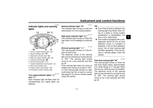 19
19 20
20 21
21 22
22 23
23 24
24 25
25 26
26 27
27 28
28 29
29 30
30 31
31 32
32 33
33 34
34 35
35 36
36 37
37 38
38 39
39 40
40 41
41 42
42 43
43 44
44 45
45 46
46 47
47 48
48 49
49 50
50 51
51 52
52 53
53 54
54 55
55 56
56 57
57 58
58 59
59 60
60 61
61 62
62 63
63 64
64 65
65 66
66 67
67 68
68 69
69 70
70 71
71 72
72 73
73 74
74 75
75 76
76 77
77 78
78 79
79 80
80 81
81 82
82 83
83 84
84 85
85 86
86 87
87 88
88 89
89 90
90 91
91 92
92 93
93 94
94 95
95 96
96 97
97 98
98 99
99 100
100 101
101 102
102 103
103 104
104 105
105 106
106 107
107 108
108 109
109 110
110 111
111 Message “Lo” is displayed. OK. Go ahead with riding.
40–116 °C
(104–242 °F) Coolant temper")