Page 65 of 128
.
Slow compression damping force
To increase the compression d")
Instrument and control functions
4-44
1
2
345
6
7
8
9
10
11
12
by soften the compression damping,
turn the adjusting bolt in direction (b).
Slow compression damping force
To increase the compression damping
force and thereby harden the slow
compression damping, turn the adjust-
ing screw in direction (a). To decrease the compression damping force and
thereby soften the compression damp-
ing, turn the adjusting screw in direction
(b).
TIPTo obtain a precise adjustment, it is ad-
visable to check the actual total number
of clicks or turns of each damping forceadjusting mechanism. This adjustment
range may not exactly match the spec-
ifications listed due to small differences
in production.
For YZF-R1M:
This model is is equipped with ÖHLINS
electronic racing suspension.
Compression damping force and
rebound damping force
The compression and rebound damp-
ing forces are electronically controlled
and can be adjusted from the MENU
screen. See ERS on page 4-19 for in-
formation on how to adjust these set-
tings.
Spring preload
The spring preload adjustment is per-
formed manually.NOTICE
ECA10102
To avoid damaging the mechanism,
do not attempt to turn beyond themaximum or minimum settings.
1. Loosen the locknut.
2. To increase the spring preload and
1. Fast compression damping force adjusting boltFast compression damping settingMinimum (soft):
5.5 turn(s) in direction (b)*
Standard: 3 turn(s) in direction (b)*
Maximum (hard): 0 turn(s) in direction (b)*
* With the adjusting bolt fully turned in
direction (a)
(a) (b)
1
1. Slow compression damping force
adjusting screwSlow compression damping settingMinimum (soft):
18 click(s) in direction (b)*
Standard: 10 click(s) in direction (b)*
Maximum (hard): 0 click(s) in direction (b)*
* With the adjusting screw fully turned
in direction (a)
(a) (b)
1
2CR-9-E1.book 44 ページ 2015年8月20日 木曜日 午後4時46分
Page 66 of 128
. To decrease the spring pre-
load and thereby soften the sus-
pe")
Instrument and control functions
4-45
1
2
34
5
6
7
8
9
10
11
12 thereby harden the suspension,
turn the adjusting ring in direction
(a). To decrease the spring pre-
load and thereby soften the sus-
pension, turn the adjusting ring in
direction (b).
The spring preload setting is deter-
mined by measuring distance A.
The longer distance A is, the high-
er the spring preload; the shorter
distance A is, the lower the spring
preload.
Use the special wrench in the
owner’s tool kit to make the ad-
justment.
3. Tighten the locknut to the specifiedtorque. NOTICE: Always tighten
the locknut against the adjust-
ing ring, and then tighten the
locknut to the specified
torque.
[ECA22760] EAU67050
EXUP systemThis model is equipped with Yamaha’s
EXUP (EXhaust Ultimate Power valve)
system. This system boosts engine
power by means of a valve that controls
exhaust flow within the exhaust cham-
ber.NOTICE
ECA15611
The EXUP system has been set and
extensively tested at the Yamaha
factory. Changing these settings
without sufficient technical knowl-
edge may result in poor perfor-mance of or damage to the engine.
1. Spring preload adjusting ring
2. Locknut
1
(a) (b)
2
1. Distance ASpring preload:
Minimum (soft):
Distance A = 0 mm (0.00 in)
Standard: Distance A = 4 mm (0.16 in)
Maximum (hard): Distance A = 9 mm (0.35 in)
Tightening torque: Locknut:
25 Nm (2.5 m·kgf, 18 ft·lbf)
1
2CR-9-E1.book 45 ページ 2015年8月20日 木曜日 午後4時46分
Page 67 of 128

Instrument and control functions
4-46
1
2
345
6
7
8
9
10
11
12
EAU70640
Auxiliary DC connectorThis vehicle is equipped with an auxilia-
ry DC connector. Consult your Yamaha
dealer before installing any accesso-
ries.
EAU15306
SidestandThe sidestand is located on the left side
of the frame. Raise the sidestand or
lower it with your foot while holding the
vehicle upright.TIPThe built-in sidestand switch is part of
the ignition circuit cut-off system, which
cuts the ignition in certain situations.
(See the following section for an expla-
nation of the ignition circuit cut-off sys-tem.)
WARNING
EWA10242
The vehicle must not be ridden with
the sidestand down, or if the sides-
tand cannot be properly moved up
(or does not stay up), otherwise the
sidestand could contact the ground
and distract the operator, resulting
in a possible loss of control.
Yamaha’s ignition circuit cut-off
system has been designed to assist
the operator in fulfilling the respon-
sibility of raising the sidestand be-
fore starting off. Therefore, check
this system regularly and have a Yamaha dealer repair it if it does not
function properly.
2CR-9-E1.book 46 ページ 2015年8月20日 木曜日 午後4時46分
Page 68 of 128
Instrument and control functions
4-47
1
2
34
5
6
7
8
9
10
11
12
EAU44893
Ignition circuit cut-off systemThe ignition circuit cut-off system (com-
prising the sidestand switch, clutch
switch and neutral switch) has the fol-
lowing functions.
It prevents starting when the trans-
mission is in gear and the sides-
tand is up, but the clutch lever is
not pulled.
It prevents starting when the trans-
mission is in gear and the clutch le-
ver is pulled, but the sidestand is
still down.
It cuts the running engine when the
transmission is in gear and the sid-
estand is moved down.
Periodically check the operation of the
ignition circuit cut-off system according
to the following procedure.
2CR-9-E1.book 47 ページ 2015年8月20日 木曜日 午後4時46分
Page 69 of 128

Instrument and control functions
4-48
1
2
345
6
7
8
9
10
11
12
With the engine turned off:
1. Move the sidestand down.
2. Make sure that the engine stop switch is set to “
3. Turn the key on.
4. Shift the transmission into the neutral position.
5. Push the start switch.
Does the engine start?
With the engine still running:
6. Move the sidestand up.
7. Keep the clutch lever pulled.
8. Shift the transmission into gear.
9. Move the sidestand down.
Does the engine stall?
After the engine has stalled:
10. Move the sidestand up.
11. Keep the clutch lever pulled.
12. Push the start switch.
Does the engine start?
The system is OK. The motorcycle can be ridden. The neutral switch may not be working correctly.
The motorcycle should not be ridden until
checked by a Yamaha dealer.
The sidestand switch may not be working correctly.
The motorcycle should not be ridden until
checked by a Yamaha dealer.
The clutch switch may not be working correctly.
The motorcycle should not be ridden until
checked by a Yamaha dealer.
YES NO YES NO YES NO
If a malfunction is noted, have a Yamaha
dealer check the system before riding.
WARNING
”.
2CR-9-E1.book 48 ページ 2015年8月20日 木曜日 午後4時46分
Page 70 of 128

5-1
1
2
3
45
6
7
8
9
10
11
12
For your safety – pre-operation checks
EAU15599
Inspect your vehicle each time you use it to make sure the vehi cle is in safe operating condition. Always follow the inspection
and maintenance procedures and schedules described in the Owner’s Manual.
WARNING
EWA11152
Failure to inspect or maintain the vehicle properly increases the possibility of an accident or equipment damage.
Do not operate the vehicle if you find any problem. If a problem cannot be corrected by the procedures provided inthis manual, have the vehicle inspected by a Yamaha dealer.
Before using this vehicle, check the following points:
ITEM CHECKS PAGE
Fuel Check fuel level in fuel tank.
Refuel if necessary.
Check fuel line for leakage.
Check fuel tank breather hose and overflow hose for obstructions, cracks or
damage, and check hose connections. 4-34, 4-35
Engine oil Check oil level in engine.
If necessary, add recommended oil to specified level.
Check vehicle for oil leakage. 7-12
Coolant Check coolant level in reservoir.
If necessary, add recommended coolant to specified level.
Check cooling system for leakage. 7-14
Front brake Check operation.
If soft or spongy, have Yamaha dealer bleed hydraulic system.
Check brake pads for wear.
Replace if necessary.
Check fluid level in reservoir.
If necessary, add specified brake fluid to specified level.
Check hydraulic system for leakage. 7-23, 7-24
2CR-9-E1.book 1 ページ 2015年8月20日 木曜日 午後4時46分
Page 71 of 128

For your safety – pre-operation checks
5-2
1
2
3
456
7
8
9
10
11
12
Rear brake Check operation.
If soft or spongy, have Yamaha dealer bleed hydraulic system.
Check brake pads for wear.
Replace if necessary.
Check fluid level in reservoir.
If necessary, add specified brake fluid to specified level.
Check hydraulic system for leakage. 7-23, 7-24
Clutch Check operation.
Lubricate cable if necessary.
Check lever free play.
Adjust if necessary. 7-22
Throttle grip Make sure that operation is smooth.
Check throttle grip free play.
If necessary, have Yamaha dealer adjust th
rottle grip free play and lubricate cable
and grip housing. 7-18, 7-28
Control cables Make sure that operation is smooth.
Lubricate if necessary. 7-27
Drive chain Check chain slack.
Adjust if necessary.
Check chain condition.
Lubricate if necessary. 7-25, 7-27
Wheels and tires Check for damage.
Check tire condition and tread depth.
Check air pressure.
Correct if necessary. 7-18, 7-21
Brake and shift pedals Make sure that operation is smooth.
Lubricate pedal pivoting points if necessary. 7-28
Brake and clutch levers Make sure that operation is smooth.
Lubricate lever pivoting points if necessary. 7-29
Sidestand Make sure that operation is smooth.
Lubricate pivot if necessary. 7-29
Chassis fasteners Make sure that all nuts, bolts and screws are properly tightened.
Tighten if necessary. —
ITEM CHECKS PAGE
2CR-9-E1.book 2 ページ 2015年8月20日 木曜日 午後4時46分
Page 72 of 128
For your safety – pre-operation checks
5-3
1
2
3
45
6
7
8
9
10
11
12
Air intake duct Make sure that the air intake duct is not blocked.
Remove any foreign objects from the screen if necessary. —
Instruments, lights, signals
and switches Check operation.
Correct if necessary.
—
Sidestand switch Check operation of ignition circuit cut-off system.
If system is not working correctly, have Yamaha dealer check vehicle. 4-46
ITEM CHECKS PAGE
2CR-9-E1.book 3 ページ 2015年8月20日 木曜日 午後4時46分
 1
1 2
2 3
3 4
4 5
5 6
6 7
7 8
8 9
9 10
10 11
11 12
12 13
13 14
14 15
15 16
16 17
17 18
18 19
19 20
20 21
21 22
22 23
23 24
24 25
25 26
26 27
27 28
28 29
29 30
30 31
31 32
32 33
33 34
34 35
35 36
36 37
37 38
38 39
39 40
40 41
41 42
42 43
43 44
44 45
45 46
46 47
47 48
48 49
49 50
50 51
51 52
52 53
53 54
54 55
55 56
56 57
57 58
58 59
59 60
60 61
61 62
62 63
63 64
64 65
65 66
66 67
67 68
68 69
69 70
70 71
71 72
72 73
73 74
74 75
75 76
76 77
77 78
78 79
79 80
80 81
81 82
82 83
83 84
84 85
85 86
86 87
87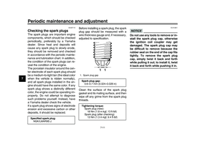 88
88 89
89 90
90 91
91 92
92 93
93 94
94 95
95 96
96 97
97 98
98 99
99 100
100 101
101 102
102 103
103 104
104 105
105 106
106 107
107 108
108 109
109 110
110 111
111 112
112 113
113 114
114 115
115 116
116 117
117 118
118 119
119 120
120 121
121 122
122 123
123 124
124 125
125 126
126 127
127
