Page 57 of 96

Periodic maintenance and adjustment
6-19
1
2
3
4
5
6
7
8
9
10
11
12
13
14
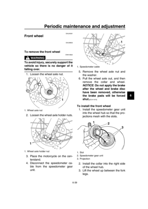
EAU48444
Adjusting the brake lever free
play
Measure the brake lever free play as
shown.
Periodically check the brake lever free
play and, if necessary, adjust it as fol-
lows.
1. Slide the rubber cover back at the brake lever.
2. Loosen the locknut.
3. To increase the brake lever free play, turn the brake lever free play
adjusting screw in direction (a). To
decrease the brake lever free play,
turn the adjusting screw in direc-
tion (b).
4. Tighten the locknut, and then slide the rubber cover back to its original
position.
WARNING
EWA10631
After adjusting the brake lever
free play, check the free play
and make sure that the brake is working properly.
A soft or spongy feeling in the
brake lever can indicate the
presence of air in the hydraulic
system. If there is air in the hy-
draulic system, have a Yamaha
dealer bleed the system before
operating the motorcycle. Air in
the hydraulic system will dimin-
ish the braking performance,
which may result in loss of con-
trol and an accident.
Brake lever free play:
5.0–8.0 mm (0.20–0.31 in)
1. Locknut
2. Brake lever free play adjusting screw
3. Rubber cover
4. Brake lever free play
2 3
1
(a)
(b)
4
2RD-28199-E1.book 19 ページ 2015年9月3日 木曜日 午後3時42分
Page 58 of 96

Periodic maintenance and adjustment
6-20
1
2
3
4
5
6
7
8
9
10
11
12
13
14
EAU22199
Adjusting the brake pedal
height and free play
WARNING
EWA10671
It is advisable to have a Yamaha
dealer make these adjustments.
Brake pedal height
The top of the brake pedal should be
positioned at the specified distance be-
low the top of the footrest as shown.
Periodically check the brake pedal
height and, if necessary, adjust it as fol-
lows. 1. Loosen the brake pedal height locknut.
2. To raise the brake pedal, turn the brake pedal height adjusting bolt in
direction (a). To lower the brake
pedal, turn the adjusting bolt in di-
rection (b). 3. Tighten the locknut.
WARNING
EWA11232
After adjusting the brake pedal
height, the brake pedal free play
must be adjusted.
Brake pedal free play
Measure the brake pedal free play as
shown.
Periodically check the brake pedal free
play and, if necessary, adjust it as fol-
lows.
To increase the brake pedal free play,
turn the brake pedal free play adjusting
nut at the brake rod in direction (a). To
Brake pedal height:
20.0 mm (0.79 in)
1. Brake pedal height
1
1. Brake pedal height locknut
2. Brake pedal height adjusting bolt
1. Brake pedal free play
Brake pedal free play:20.0–30.0 mm (0.79–1.18 in)
1
2
(b)
(a)
1
2RD-28199-E1.book 20 ページ 2015年9月3日 木曜日 午後3時42分
Page 59 of 96
Periodic maintenance and adjustment
6-21
1
2
3
4
5
6
7
8
9
10
11
12
13
14
decrease the brake pedal free play,
turn the adjusting nut in direction (b).
WARNING
EWA10681
After adjusting the drive chain
slack or removing and installing
the rear wheel, always check the
brake pedal free play.
If proper adjustment cannot be
obtained as described, have a
Yamaha dealer make this ad-
justment.
After adjusting the brake pedal
free play, check the operation of
the brake light.
EAU44821
Checking the shift pedal
The operation of the shift pedal should
be checked before each ride. If opera-
tion is not smooth, have a Yamaha
dealer check the vehicle.
1. Brake pedal free play adjusting nut
(b)
(a)
1
2RD-28199-E1.book 21 ページ 2015年9月3日 木曜日 午後3時42分
Page 60 of 96

Periodic maintenance and adjustment
6-22
1
2
3
4
5
6
7
8
9
10
11
12
13
14
EAU22274
Brake light switches
The brake light, which is activated by
the brake pedal and brake lever, should
come on just before braking takes ef-
fect. If necessary, adjust the rear brake
light switch as follows, but the front
brake light switch should be adjusted
by a Yamaha dealer.
Turn the rear brake light switch adjust-
ing nut while holding the rear brake light
switch in place. To make the brake light
come on earlier, turn the adjusting nut
in direction (a). To make the brake light
come on later, turn the adjusting nut in
direction (b).
EAU22382
Checking the front brake pads
and rear brake shoes
The front brake pads and the rear brake
shoes must be checked for wear at the
intervals specified in the periodic main-
tenance and lubrication chart.
EAU22432Front brake pads
Each front brake pad is provided with
wear indicator grooves, which allow
you to check the brake pad wear with-
out having to disassemble the brake.
To check the brake pad wear, check
the wear indicator grooves. If a brake
pad has worn to the point that the wear
indicator grooves have almost disap-
peared, have a Yamaha dealer replace
the brake pads as a set.
1. Rear brake light switch adjusting nut
2. Rear brake light switch
2
1 (a)
(b)
1. Brake pad
2. Brake pad wear indicator groove
12
2RD-28199-E1.book 22 ページ 2015年9月3日 木曜日 午後3時42分
Page 61 of 96

Periodic maintenance and adjustment
6-23
1
2
3
4
5
6
7
8
9
10
11
12
13
14
EAU22541Rear brake shoes
The rear brake is provided with a wear
indicator, which allows you to check the
brake shoe wear without having to dis-
assemble the brake. To check the
brake shoe wear, check the position of
the wear indicator while applying the
brake. If a brake shoe has worn to the
point that the wear indicator reaches
the wear limit line, have a Yamaha
dealer replace the brake shoes as a
set.EAU32346
Checking the brake fluid level
Before riding, check that the brake fluid
is above the minimum level mark.
Check the brake fluid level with the top
of the reservoir level. Replenish the
brake fluid if necessary.
WARNING
EWA15991
Improper maintenance can result in
loss of braking ability. Observe
these precautions:
Insufficient brake fluid may al-
low air to enter the brake sys-
tem, reducing braking
performance.
Clean the filler cap before re-
moving. Use only DOT 4 brake
fluid from a sealed container.
Use only the specified brake flu-
id; otherwise, the rubber seals
may deteriorate, causing leak-
age.
Refill with the same type of
brake fluid. Adding a brake fluid
other than DOT 4 may result in a
harmful chemical reaction.
Be careful that water does not
enter the brake fluid reservoir
1. Brake shoe wear indicator
2. Brake shoe wear limit line
1 2
1. Minimum level mark
Specified brake fluid:
DOT 4
1
2RD-28199-E1.book 23 ページ 2015年9月3日 木曜日 午後3時42分
Page 62 of 96

Periodic maintenance and adjustment
6-24
1
2
3
4
5
6
7
8
9
10
11
12
13
14 when refilling. Water will signifi-
cantly lower the boiling point of
the fluid and may result in vapor
lock.
NOTICE
ECA17641
Brake fluid may damage painted sur-
faces or plastic parts. Always clean
up spilled fluid immediately.
As the brake pads wear, it is normal for
the brake fluid level to gradually go
down. A low brake fluid level may indi-
cate worn brake pads and/or brake sys-
tem leakage; therefore, be sure to
check the brake pads for wear and the
brake system for leakage. If the brake
fluid level goes down suddenly, have a
Yamaha dealer check the cause before
further riding.
EAU22724
Changing the brake fluid
Have a Yamaha dealer change the
brake fluid at the intervals specified in
the periodic maintenance and lubrica-
tion chart. In addition, have the oil seals
of the brake master cylinder and caliper
as well as the brake hose replaced at
the intervals listed below or whenever
they are damaged or leaking.
Oil seals: Replace every two
years.
Brake hose: Replace every four
years.
2RD-28199-E1.book 24 ページ 2015年9月3日 木曜日 午後3時42分
Page 63 of 96

Periodic maintenance and adjustment
6-25
1
2
3
4
5
6
7
8
9
10
11
12
13
14
EAU22762
Drive chain slack
The drive chain slack should be
checked before each ride and adjusted
if necessary.
EAU59593To check the drive chain slack 1. Place the motorcycle on the cen- terstand.
2. Shift the transmission into the neu- tral position.
3. Push on the drive chain at the cen- ter point between the drive axle
and the rear wheel axle with a
force of 50 N (5.0 kgf, 11 lbf).
4. Measure the drive chain slack as shown.
5. If the drive chain slack is incorrect, adjust it as follows.
EAU59642To adjust the drive chain slack
Consult a Yamaha dealer before ad-
justing the drive chain slack.1. Take the motorcycle off the center- stand, and then put the sidestand
down.
2. Loosen the brake pedal free play adjusting nut, brake torque rod nut,
and axle nut.
3. Loosen the drive chain puller lock- nut at each end of the swingarm.
4. Place the motorcycle on the cen- terstand.
5. To tighten the drive chain, turn the drive chain slack adjusting bolt at
each end of the swingarm in direc-
tion (a). To loosen the drive chain,
turn the adjusting bolt at each end
of the swingarm in direction (b),
and then push the rear wheel for-
ward. NOTICE: Improper drive
chain slack will overload the en-
gine as well as other vital parts
of the motorcycle and can lead
to chain slippage or breakage.
To prevent this from occurring,
keep the drive chain slack with-
in the specified limits.[ECA10572]
TIP
Using the alignment marks on each
side of the swingarm, make sure that
both drive chain pullers are in the same
position for proper wheel alignment.
Drive chain slack: 30.0–40.0 mm (1.18–1.57 in)
1. Drive chain slack
1
1. Brake pedal free play adjusting nut
2. Drive chain slack adjusting bolt
3. Drive chain puller locknut
4. Axle nut
5. Brake torque rod nut
6. Brake torque rod
6
12
3
4
5
2RD-28199-E1.book 25 ページ 2015年9月3日 木曜日 午後3時42分
Page 64 of 96

Periodic maintenance and adjustment
6-26
1
2
3
4
5
6
7
8
9
10
11
12
13
14 6. Take the motorcycle off the center-
stand, and then put the sidestand
down.
7. Tighten both drive chain puller locknuts to the specified torque,
and then tighten the axle nut and
brake torque rod nut to their speci-
fied torques.
8. Adjust the brake pedal free play. (See page 6-20.)
WARNING
EWA10661
After adjusting the brake pedal free
play, check the operation of the
brake light.
9. Make sure that the drive chain pull- ers are in the same position, the
drive chain slack is correct, and the
drive chain moves smoothly.
EAU23026
Cleaning and lubricating the
drive chain
The drive chain must be cleaned and
lubricated at the intervals specified in
the periodic maintenance and lubrica-
tion chart, otherwise it will quickly wear
out, especially when riding in dusty or
wet areas. Service the drive chain as
follows.
NOTICE
ECA10584
The drive chain must be lubricated
after washing the motorcycle, riding
in the rain or riding in wet areas.
1. Clean the drive chain with kero- sene and a small soft brush.
NOTICE: To prevent damaging
the O-rings, do not clean the
drive chain with steam cleaners,
high-pressure washers or inap-
propriate solvents.
[ECA11122]
2. Wipe the drive chain dry.
3. Thoroughly lubricate the drive chain with a special O-ring chain
lubricant. NOTICE: Do not use
engine oil or any other lubri-
cants for the drive chain, as they
may contain substances that
could damage the O-rings.
[ECA11112]
1. Axle nut
2. Drive chain puller locknut
3. Drive chain slack adjusting bolt
4. Alignment marks
Tightening torques: Drive chain puller locknut:16 Nm (1.6 m·kgf, 12 ft·lbf)
Axle nut: 129 Nm (12.9 m·kgf, 92 ft·lbf)
Brake torque rod nut:
19 Nm (1.9 m·kgf, 14 ft·lbf)
1
2
(a) (b)
3
4
2RD-28199-E1.book 26 ページ 2015年9月3日 木曜日 午後3時42分


.
WARNING
EWA10681
After adjusting the drive cha")