Page 73 of 96

Periodic maintenance and adjustment
6-35
1
2
3
4
5
6
7
8
9
10
11
12
13
14
EAU23799
Replacing the headlight bulb
This model is equipped with a halogen
bulb headlight. If the headlight bulb
burns out, replace it as follows.
NOTICE
ECA10651
Take care not to damage the follow-
ing parts:
Headlight bulb
Do not touch the glass part of
the headlight bulb to keep it free
from oil, otherwise the transpar-
ency of the glass, the luminosity
of the bulb, and the bulb life will
be adversely affected. Thor-
oughly clean off any dirt and fin-
gerprints on the headlight bulb
using a cloth moistened with al-
cohol or thinner.
Headlight lens
Do not affix any type of tinted
film or stickers to the headlight
lens.
Do not use a headlight bulb of a
wattage higher than specified.
1. Remove the headlight unit by re- moving the screws. 2. Disconnect the headlight coupler,
and then remove the headlight
bulb cover.
3. Unhook the headlight bulb holder, and then remove the burnt-out
bulb.
1. Do not touch the glass part of the bulb.
1. Screw
1. Screw
1. Headlight coupler
2. Headlight bulb cover
1
1
1
2
2RD-28199-E1.book 35 ページ 2015年9月3日 木曜日 午後3時42分
Page 74 of 96
Periodic maintenance and adjustment
6-36
1
2
3
4
5
6
7
8
9
10
11
12
13
14 4. Place a new headlight bulb into po-
sition, and then secure it with the
bulb holder.
5. Install the bulb cover, and then connect the coupler.
6. Install the headlight unit by install- ing the screws.
7. Have a Yamaha dealer adjust the headlight beam if necessary.
EAU33417
Replacing the auxiliary light
bulb
If the auxiliary light bulb burns out, re-
place it as follows.1. Remove the headlight unit by re- moving the screws.
2. Remove the socket (together with the bulb) by pushing it in and turn-
ing it counterclockwise.
1. Headlight bulb holder
1
1. Screw
1. Screw
1. Auxiliary light bulb socket
1
1
1
2RD-28199-E1.book 36 ページ 2015年9月3日 木曜日 午後3時42分
Page 75 of 96

Periodic maintenance and adjustment
6-37
1
2
3
4
5
6
7
8
9
10
11
12
13
14
3. Remove the burnt-out bulb by
pushing it in and turning it counter-
clockwise.
4. Insert a new bulb into the socket, push it in, and then turn it clock-
wise until it stops.
5. Install the socket (together with the bulb) by pushing it in and turning it
clockwise until it stops.
6. Install the headlight unit by install- ing the screws.
EAU24135
Replacing the tail/brake light
bulb
1. Remove the tail/brake light lens byremoving the screws.
2. Remove the burnt-out bulb by pushing it in and turning it counter-
clockwise.
3. Insert a new bulb into the socket, push it in, and then turn it clock-
wise until it stops.
4. Install the lens by installing the screws. NOTICE: Do not over-
tighten the screws, otherwise
the lens may break.
[ECA10682]
1. Auxiliary light bulb socket
2. Auxiliary light bulb
1
2
1. Screw
2. Tail/brake light lens
1. Tail/brake light bulb
1 2
1
2RD-28199-E1.book 37 ページ 2015年9月3日 木曜日 午後3時42分
Page 76 of 96
Periodic maintenance and adjustment
6-38
1
2
3
4
5
6
7
8
9
10
11
12
13
14
EAU60010
Replacing a turn signal light
bulb
1. Remove the turn signal light lens, turn signal light rim and gasket by
removing the screws.
2. Remove the burnt-out bulb by pushing it in and turning it counter-
clockwise.
3. Insert a new bulb into the socket, push it in, and then turn it clock-
wise until it stops.
4. Install the gasket, rim and lens by installing the screws with the notch
on the rim and lens facing to in-
ward as shown. NOTICE: Do not
overtighten the screws, other-
wise the lens may break.
[ECA10682]
1. Turn signal light lens
2. Screw
1. Turn signal light lens
2. Turn signal light rim
3. Gasket
1
2
3
2
1
2RD-28199-E1.book 38 ページ 2015年9月3日 木曜日 午後3時42分
Page 77 of 96

Periodic maintenance and adjustment
6-39
1
2
3
4
5
6
7
8
9
10
11
12
13
14
EAU24361
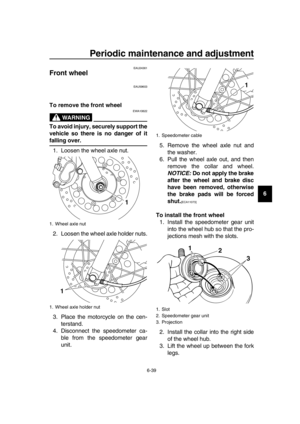
Front wheel
EAU59603
To remove the front wheel
WARNING
EWA10822
To avoid injury, securely support the
vehicle so there is no danger of it
falling over. 1. Loosen the wheel axle nut.
2. Loosen the wheel axle holder nuts.
3. Place the motorcycle on the cen- terstand.
4. Disconnect the speedometer ca- ble from the speedometer gear
unit. 5. Remove the wheel axle nut and
the washer.
6. Pull the wheel axle out, and then remove the collar and wheel.
NOTICE: Do not apply the brake
after the wheel and brake disc
have been removed, otherwise
the brake pads will be forced
shut.
[ECA11073]
To install the front wheel1. Install the speedometer gear unit into the wheel hub so that the pro-
jections mesh with the slots.
2. Install the collar into the right side of the wheel hub.
3. Lift the wheel up between the fork legs.
1. Wheel axle nut
1. Wheel axle holder nut
1
1
1. Speedometer cable
1. Slot
2. Speedometer gear unit
3. Projection
1
2
3
1
2RD-28199-E1.book 39 ページ 2015年9月3日 木曜日 午後3時42分
Page 78 of 96

Periodic maintenance and adjustment
6-40
1
2
3
4
5
6
7
8
9
10
11
12
13
14
TIP
Make sure that there is enough space
between the brake pads before insert-
ing the brake disc and that the slot in
the speedometer gear unit fits over the
retainer on the fork leg.
4. Insert the wheel axle from the left side, and then install the washer
and axle nut.
5. Take the motorcycle off the center- stand so that the front wheel is on
the ground, and then put the side-
stand down.
6. Tighten the axle nut and the wheel axle holder nuts to their specified
torques.
7. While applying the front brake, push down hard on the handlebars
several times to check if the front
fork compresses and rebounds
smoothly.
8. Connect the speedometer cable.
EAU25081
Rear wheel
EAU59614
To remove the rear wheel
WARNING
EWA10822
To avoid injury, securely support the
vehicle so there is no danger of it
falling over.
1. Loosen the axle nut and the brake torque rod nut at the brake shoe
plate.
2. Disconnect the brake torque rod from the brake shoe plate by re-
moving the nut, washer and the
bolt.
3. Place the motorcycle on the cen- terstand.
4. Remove the brake pedal free play adjusting nut, and then disconnect
1. Retainer
2. Slot
3. Wheel axle
Tightening torques:Axle nut:
104 Nm (10.4 m·kgf, 74 ft·lbf)
Wheel axle holder nut: 9 Nm (0.9 m·kgf, 6.5 ft·lbf)
1
3 2
1. Brake rod
2. Brake camshaft lever
3. Brake pedal free play adjusting nut
4. Drive chain slack adjusting bolt
5. Drive chain puller locknut
6. Drive chain puller
7. Washer
8. Axle nut
9. Brake torque rod nut
10.Brake torque rod
1
10
34
5
6
7
8
9
7
2
2RD-28199-E1.book 40 ページ 2015年9月3日 木曜日 午後3時42分
Page 79 of 96

Periodic maintenance and adjustment
6-41
1
2
3
4
5
6
7
8
9
10
11
12
13
14
the brake rod from the brake cam-
shaft lever.
5. Loosen the drive chain puller lock- nut and the drive chain slack ad-
justing bolt on both ends of the
swingarm.
6. Remove the axle nut and washer.
7. While supporting the rear wheel, pull the wheel axle out.
8. Remove the chain pullers and the spacer.
9. Push the wheel forward, and then remove the drive chain from the
rear sprocket.
TIP
The drive chain does not need to be
disassembled in order to remove and
install the wheel.
To install the rear wheel1. Install the spacer into left side of the wheel hub.
2. Install the chain pullers and the wheel by inserting the wheel axle
from the left side.
3. Install the drive chain onto the rear sprocket.
4. Install the washer and axle nut.
5. Install the brake rod onto the brake camshaft lever, and then install the
brake pedal free play adjusting nut
onto the brake rod.
6. Connect the brake torque rod to the brake shoe plate by installing
the bolt, washer and nut.
7. Adjust the drive chain slack. (See page 6-25.)
8. Take the motorcycle off the center- stand so that the rear wheel is on
the ground, and then put the side-
stand down.
9. Tighten the brake torque rod nut and axle nut to the specified
torques.
10. Adjust the brake pedal free play. (See page 6-20.)
WARNING
EWA10661
After adjusting the brake pedal free
play, check the operation of the
brake light.
1. Drive chain slack adjusting bolt
2. Drive chain puller locknut
3. Axle nut
4. Washer
1. Drive chain
3
2
14
1
Tightening torques:
Brake torque rod nut: 19 Nm (1.9 m·kgf, 14 ft·lbf)
Axle nut: 129 Nm (12.9 m·kgf, 92 ft·lbf)
2RD-28199-E1.book 41 ページ 2015年9月3日 木曜日 午後3時42分
Page 80 of 96

Periodic maintenance and adjustment
6-42
1
2
3
4
5
6
7
8
9
10
11
12
13
14
EAU25852
Troubleshooting
Although Yamaha motorcycles receive
a thorough inspection before shipment
from the factory, trouble may occur dur-
ing operation. Any problem in the fuel,
compression, or ignition systems, for
example, can cause poor starting and
loss of power.
The following troubleshooting chart
represents a quick and easy procedure
for checking these vital systems your-
self. However, should your motorcycle
require any repair, take it to a Yamaha
dealer, whose skilled technicians have
the necessary tools, experience, and
know-how to service the motorcycle
properly.
Use only genuine Yamaha replace-
ment parts. Imitation parts may look like
Yamaha parts, but they are often inferi-
or, have a shorter service life and can
lead to expensive repair bills.
WARNING
EWA15142
When checking the fuel system, do
not smoke, and make sure there are
no open flames or sparks in the ar-
ea, including pilot lights from water
heaters or furnaces. Gasoline or
gasoline vapors can ignite or ex-
plode, causing severe injury or
property damage.
2RD-28199-E1.book 42 ページ 2015年9月3日 木曜日 午後3時42分