Page 13 of 594

General information
&California proposition 65
warning
WARNING
Engine exhaust, some of its consti-
tuents, and certain vehicle compo-
nents contain or emit chemicals
known to the State of California to
cause cancer and birth defects or
other reproductive harm. In addi-
tion, certain fluids in vehicles and
certain components of product wear
contain or emit chemicals known to
the State of California to cause
cancer and birth defects or other
reproductive harm.
&California Perchlorate Advi-
sory
Certain vehicle components such as air-
bag modules, seatbelt pretensioners and
keyless entry transmitter batteries may
contain perchlorate material. Special
handling may apply for service or vehicle
end of life disposal. See www.dtsc.ca.gov/
hazardouswaste/perchlorate.
&Noise from under the vehicle
NOTE
You may hear a noise from under the
vehicle approximately 5 to 10 hours
after the ignition switch is turned to the
“LOCK ”/“OFF ”position. However, this
does not indicate a malfunction. This
noise is caused by the operation of the
fuel evaporation leakage checking sys-
tem and the operation is normal. The
noise will stop after approximately 15
minutes.
& Event data recorder
This vehicle is equipped with an event
data recorder (EDR). The main purpose of
an EDR is to record, in certain crash or
near crash-like situations, such as an air
bag deployment or hitting a road obstacle,
data that will assist in understanding how
a vehicle’ s systems performed. The EDR
is designed to record data related to
vehicle dynamics and safety systems for
a short period of time, typically 30 seconds
or less. The EDR in this vehicle is
designed to record such data as:
. How various systems in your vehicle
were operating;
. Whether or not the driver and passen-
ger safety belts were buckled/fastened;
. How far (if at all) the driver was depressing the accelerator and/or brake
pedal; and,
.
How fast the vehicle was traveling.
These data can help provide a better
understanding of the circumstances in
which crashes and injuries occur. NOTE:
EDR data are recorded by your vehicle
only if a non-trivial crash situation occurs;
no data are recorded by the EDR under
normal driving conditions and no personal
data (e.g., name, gender, age, and crash
location) are recorded. However, other
parties, such as law enforcement, could
combine the EDR data with the type of
personally identifying data routinely ac-
quired during a crash investigation.
To read data recorded by an EDR, special
equipment is required, and access to the
vehicle or the EDR is needed. In addition
to the vehicle manufacturer, other parties,
such as law enforcement, that have the
special equipment, can read the informa-
tion if they have access to the vehicle or
the EDR.
8
Page 23 of 594
&Combination meter
! U.S.-spec. models (type A)
The illustration above is a typical example. For some models, the combination meter
may be slightly different than that shown in the illustration.
1) Tachometer (page 3-11)
2) Trip meter and odometer (page 3-10)
3) Select lever/gear position indicator
(page 3-30)
4) Speedometer (page 3-10)
5) Information display selection knob (page 3-32)
6) ECO gauge (page 3-12)
7) Fuel gauge (page 3-12)
8) Trip meter A/B selection and trip meter reset knob (page 3-11)
18
Page 24 of 594
!U.S.-spec. models (type B)
The illustration above is a typical example. For some models, the combination meter
may be slightly different than that shown in the illustration.
1) Tachometer (page 3-11)
2) Multi information display (page 3-38)
3) Fuel gauge (page 3-12)
4) Select lever/gear position indicator
(page 3-30)
5) Speedometer (page 3-10)
6) Information display selection knob (page 3-32)
7) ECO gauge (page 3-12)
8) Trip meter and odometer (page 3-10)
9) Trip meter A/B selection and trip meter reset knob (page 3-11)
–CONTINUED –
19
Page 25 of 594
!Except U.S.-spec. models (type A)
The illustration above is a typical example. For some models, the combination meter
may be slightly different than that shown in the illustration.
1) Tachometer (page 3-11)
2) Trip meter and odometer (page 3-10)
3) Select lever/gear position indicator
(page 3-30)
4) Speedometer (page 3-10)
5) Information display selection knob (page 3-32)
6) ECO gauge (page 3-12)
7) Fuel gauge (page 3-12)
8) Trip meter A/B selection and trip meter reset knob (page 3-11)
20
Page 26 of 594
!Except U.S.-spec. models (type B)
The illustration above is a typical example. For some models, the combination meter
may be slightly different than that shown in the illustration.
1) Tachometer (page 3-11)
2) Multi information display (page 3-38)
3) Fuel gauge (page 3-12)
4) Select lever/gear position indicator
(page 3-30)
5) Speedometer (page 3-10)
6) Trip meter A/B selection and trip meter reset knob (page 3-11)
7) ECO gauge (page 3-12)
8) Trip meter and odometer (page 3-10)
–CONTINUED –
21
Page 156 of 594

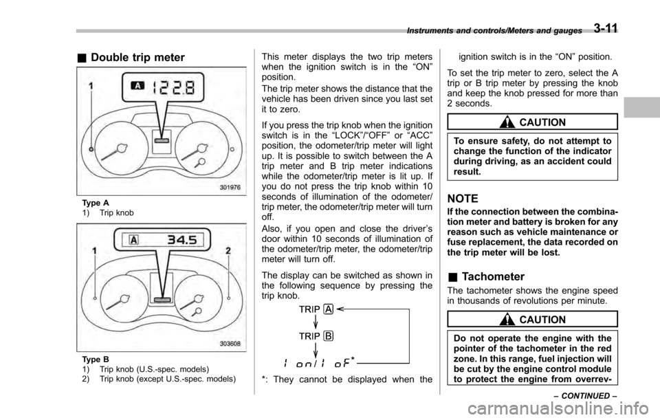
&Double trip meter
Type A
1) Trip knob
Type B
1) Trip knob (U.S.-spec. models)
2) Trip knob (except U.S.-spec. models)
This meter displays the two trip meters
when the ignition switch is in the “ON”
position.
The trip meter shows the distance that the
vehicle has been driven since you last set
it to zero.
If you press the trip knob when the ignition
switch is in the “LOCK”/ “OFF”or “ACC ”
position, the odometer/trip meter will light
up. It is possible to switch between the A
trip meter and B trip meter indications
while the odometer/trip meter is lit up. If
you do not press the trip knob within 10
seconds of illumination of the odometer/
trip meter, the odometer/trip meter will turn
off.
Also, if you open and close the driver ’s
door within 10 seconds of illumination of
the odometer/trip meter, the odometer/trip
meter will turn off.
The display can be switched as shown in
the following sequence by pressing the
trip knob.
*: They cannot be displayed when the ignition switch is in the
“ON ”position.
To set the trip meter to zero, select the A
trip or B trip meter by pressing the knob
and keep the knob pressed for more than
2 seconds.
CAUTION
To ensure safety, do not attempt to
change the function of the indicator
during driving, as an accident could
result.
NOTE
If the connection between the combina-
tion meter and battery is broken for any
reason such as vehicle maintenance or
fuse replacement, the data recorded on
the trip meter will be lost.
& Tachometer
The tachometer shows the engine speed
in thousands of revolutions per minute.
CAUTION
Do not operate the engine with the
pointer of the tachometer in the red
zone. In this range, fuel injection will
be cut by the engine control module
to protect the engine from overrev-
Instruments and controls/Meters and gauges
–CONTINUED –3-11
Page 157 of 594

Instruments and controls/Meters and gauges
ving. The engine will resume run-
ning normally after the engine speed
is reduced below the red zone.
NOTE
To protect the engine/transmission
while the select lever is in the“P ” or
“N ”position (for CVT models) or the
shift lever is in the neutral position (for
MT models), the engine is controlled so
that the engine speed may not become
too high even if the accelerator pedal is
pressed hard.
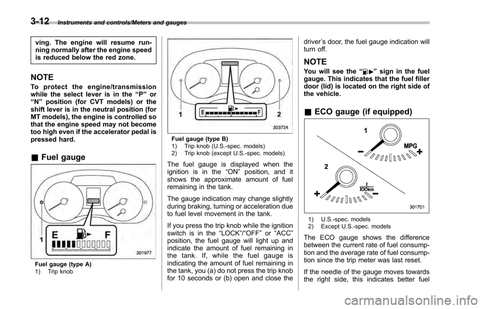
& Fuel gauge
Fuel gauge (type A)
1) Trip knob
Fuel gauge (type B)
1) Trip knob (U.S.-spec. models)
2) Trip knob (except U.S.-spec. models)
The fuel gauge is displayed when the
ignition is in the “ON”position, and it
shows the approximate amount of fuel
remaining in the tank.
The gauge indication may change slightly
during braking, turning or acceleration due
to fuel level movement in the tank.
If you press the trip knob while the ignition
switch is in the “LOCK”/ “OFF”or “ACC ”
position, the fuel gauge will light up and
indicate the amount of fuel remaining in
the tank. If, while the fuel gauge is
indicating the amount of fuel remaining in
the tank, you (a) do not press the trip knob
for 10 seconds or (b) open and close the driver
’s door, the fuel gauge indication will
turn off.
NOTE
You will see the “”sign in the fuel
gauge. This indicates that the fuel filler
door (lid) is located on the right side of
the vehicle.
& ECO gauge (if equipped)
1) U.S.-spec. models
2) Except U.S.-spec. models
The ECO gauge shows the difference
between the current rate of fuel consump-
tion and the average rate of fuel consump-
tion since the trip meter was last reset.
If the needle of the gauge moves towards
the right side, this indicates better fuel
3-12
Page 183 of 594

Instruments and controls/Multi information display (models with type B combination meter)
Multi information display
(models with type B combi-
nation meter)
WARNING
Always pay adequate attention to
safe driving when operating the
multi information display while the
vehicle is in motion. When operation
of the multi information display
interferes with your ability to con-
centrate on driving, stop the vehicle
before performing operations on the
screen. Also, do not concentrate on
the display while driving. Doing so
may cause you to look away from
the road and could result in an
accident.
Various information will be shown on the
multi information display. Also, a warning
message will appear on the display if a
malfunction, etc. is detected. In addition,
several settings for the displayed content
can be performed.
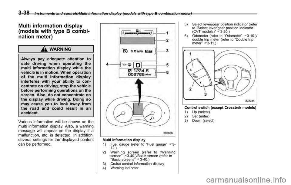
Multi information display
1) Fuel gauge (refer to “Fuel gauge ”F 3-
12.)
2) Warning screen (refer to “Warning
screen ”F 3-40.)/Basic screen (refer to
“ Basic screens ”F 3-40.)
3) Cruise control information display
4) Warning indicator 5) Select lever/gear position indicator (refer
to“Select lever/gear position indicator
(CVT models) ”F 3-30.)
6) Odometer (refer to “Odometer ”F 3-10.)/
double trip meter (refer to “Double trip
meter” F3-11.)
Control switch (except Crosstrek models)
1) Up (select)
2) Set (enter)
3) Down (select)
3-38