2016 SUBARU IMPREZA Stall test
[x] Cancel search: Stall testPage 55 of 594

Seat, seatbelt and SRS airbags/Front seatbelt pretensioners
&System monitors
A diagnostic system continually monitors
the readiness of the seatbelt pretensioner
while the vehicle is being driven. The
seatbelt pretensioners share the control
modulewiththeSRSairbagsystem.
Therefore, if any malfunction occurs in a
seatbelt pretensioner, the SRS airbag
system warning light will illuminate. For
details, refer to “SRS airbag system
monitors ”F 1-67.
& System servicing
WARNING
. When discarding a seatbelt re-
tractor assembly or scrapping
the entire vehicle damaged by a
collision, consult your SUBARU
dealer.
. Tampering with or disconnecting
the system’ s wiring could result
in accidental activation of the
seatbelt pretensioner and/or
SRS airbag or could make the
system inoperative, which may
result in serious injury. Do not
use electrical test equipment on
any circuit related to the seatbelt
pretensioner and SRS airbag
systems. For required servicing of the seatbelt pretensioner, con-
sult your nearest SUBARU deal-
er.
CAUTION
The sensors and SRS airbag control
modules are located in the following
locations.
.
Front sub sensors: on both the
right and left side at the front of
the vehicle
. Front door impact sensors: on
both front doors
. Satellite safing sensor: under the
rear center seat
. SRS airbag control module (in-
cluding the impact sensors): un-
der the center of the instrument
panel
If you need service or repair in those
areas or near the front seatbelt
retractors, have the work performed
by your authorized SUBARU dealer.
NOTE
If the front or side part of the vehicle is
damaged in an accident to the extent
that the seatbelt pretensioner does not operate, contact your SUBARU dealer
as soon as possible.
&
Precautions against vehicle
modification
Always consult your SUBARU dealer if
you want to install any accessory parts to
your vehicle.
CAUTION
Do not perform any of the following
modifications. Such modifications
can interfere with proper operation
of the seatbelt pretensioners.
. Attachment of any equipment
(bush bar, winches, snow plow,
skid plate, etc.) other than genu-
ine SUBARU accessory parts to
the front end.
. Modification of the suspension
system or front end structure.
. Installation of a tire of different
size and construction from the
tires specified on the vehicle
placard attached to the driver ’s
door pillar or specified for indivi-
dual vehicle models in this Own-
er ’s Manual.
1-24
Page 318 of 594

–Outside wireless communication
range, such as some countryside
areas
– Where the wireless communica-
tion network is congested, or where
communications are restricted
. Depending on the circumstances
and environment, the signal may be
weak or not be received. In such cases,
an error may occur.
. Top 35 entries in the preset station
list on the smartphone are displayed.
When there are more than 35 entries in
the preset station list, change the order
of the entries in the list on the smart-
phone. You can change the priority of
your preset stations within the aha
application (after disconnected from
this system) to modify the station list
shown on the screen. Please see your
smartphone aha application “Edit Pre-
sets (in Main menu) ”to modify this list.
. For operating the smartphone, see
the instruction manual that comes with
it.
. If there are multiple music files
stored on your iPhone or iPod touch,
it may take some time until playback
starts.
. Playback may be intermittent when
you switch to streaming Bluetooth
audio from aha on your smartphone device.
.
When connecting the device via
Bluetooth, the communication speed
may become slower than via USB.
! Before using aha application
In order to use the aha application on this
system, the application must be installed
on the smartphone.
! Settings required to use aha
application
. Search and download the aha applica-
tion from your smartphone app store.
–iPhone and iPod touch: Apple App
Store via iTunes
– Android device: Google Play Store
. Create an account and login to the aha
application on the smartphone.
NOTE
Please use the latest version of the aha
application.
!About app-based connected con-
tent
Requirements for using the connected
content services of the aha application
on this system.
. Latest version of the system is compa-
tible with connected content application(s)
for the smartphone, available from aha, downloaded to your smartphone.
.
A current account with a wireless
content service provider.
. A smartphone data plan: If the data
plan for your smartphone does not provide
for unlimited data usage, additional
charges from your carrier may apply for
accessing app-based connected content
via 3G, 4G, Wi-Fi or 4G LTE wireless
networks.
. Connection to the internet via 3G, 4G,
Wi-Fi or 4G LTE networks.
NOTE
. Changes to product specifications
may result in differences between the
content of the manual and features of
the product.
. Be careful not to exceed the data
usage limits for your smartphone.
Doing so will result in additional data
usage charges from your phone car-
rier.
. Access to app-based connected
content will depend on the availability
of wireless cell and/or Wi-Fi network
coverage for the purpose of allowing
your smartphone to connect to the
internet.
. Service availability may be geogra-
phically limited by region. Consult the
wireless connected content service
Audio/Audio set
–CONTINUED –5-47
Page 406 of 594

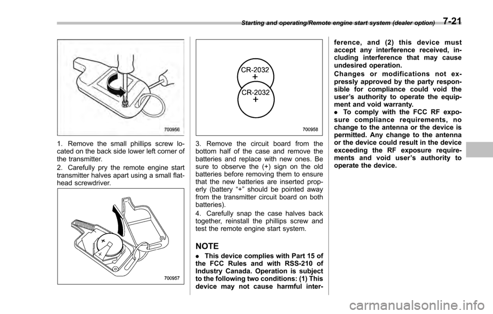
1. Remove the small phillips screw lo-
cated on the back side lower left corner of
the transmitter.
2. Carefully pry the remote engine start
transmitter halves apart using a small flat-
head screwdriver.3. Remove the circuit board from the
bottom half of the case and remove the
batteries and replace with new ones. Be
sure to observe the (+) sign on the old
batteries before removing them to ensure
that the new batteries are inserted prop-
erly (battery“+”should be pointed away
from the transmitter circuit board on both
batteries).
4. Carefully snap the case halves back
together, reinstall the phillips screw and
test the remote engine start system.
NOTE
. This device complies with Part 15 of
the FCC Rules and with RSS-210 of
Industry Canada. Operation is subject
to the following two conditions: (1) This
device may not cause harmful inter- ference, and (2) this device must
accept any interference received, in-
cluding interference that may cause
undesired operation.
Changes or modifications not ex-
pressly approved by the party respon-
sible for compliance could void the
user
’s authority to operate the equip-
ment and void warranty.
. To comply with the FCC RF expo-
sure compliance requirements, no
change to the antenna or the device is
permitted. Any change to the antenna
or the device could result in the device
exceeding the RF exposure require-
ments and void user ’s authority to
operate the device.
Starting and operating/Remote engine start system (dealer option)7-21
Page 410 of 594

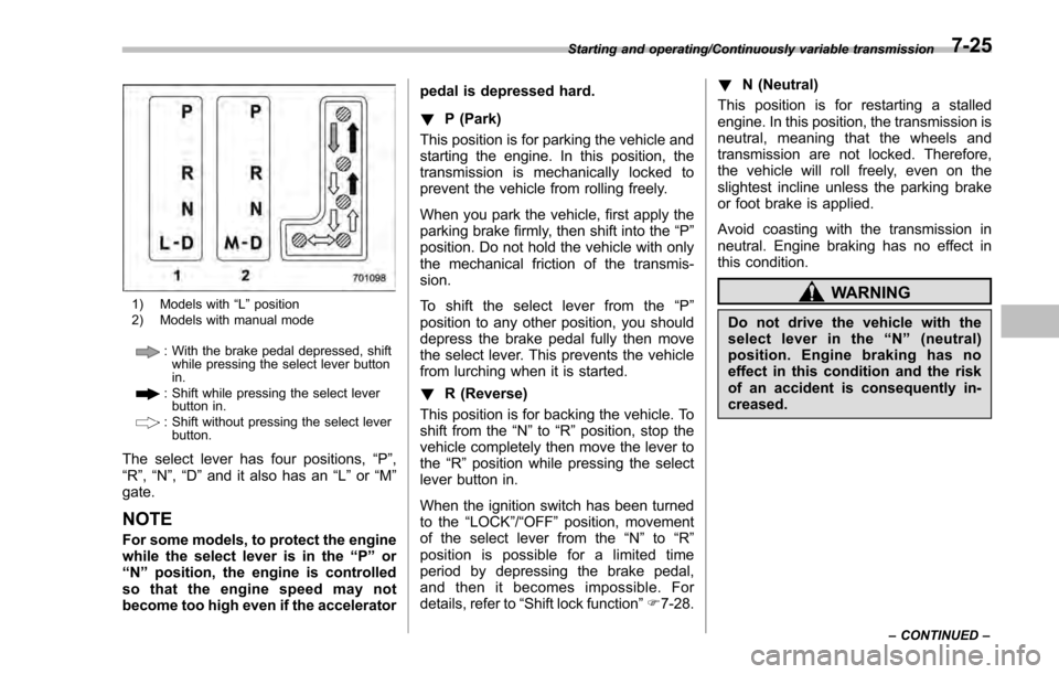
1) Models with“L ” position
2) Models with manual mode
: With the brake pedal depressed, shift while pressing the select lever button
in.
: Shift while pressing the select leverbutton in.
: Shift without pressing the select lever
button.
The select lever has four positions, “P”,
“R ”, “N ”,“D ”and it also has an “L”or “M”
gate.
NOTE
For some models, to protect the engine
while the select lever is in the “P ” or
“N ”position, the engine is controlled
so that the engine speed may not
become too high even if the accelerator pedal is depressed hard.
!
P (Park)
This position is for parking the vehicle and
starting the engine. In this position, the
transmission is mechanically locked to
prevent the vehicle from rolling freely.
When you park the vehicle, first apply the
parking brake firmly, then shift into the “P”
position. Do not hold the vehicle with only
the mechanical friction of the transmis-
sion.
To shift the select lever from the “P”
position to any other position, you should
depress the brake pedal fully then move
the select lever. This prevents the vehicle
from lurching when it is started.
! R (Reverse)
This position is for backing the vehicle. To
shift from the “N”to “R”position, stop the
vehicle completely then move the lever to
the “R”position while pressing the select
lever button in.
When the ignition switch has been turned
to the “LOCK”/“OFF ”position, movement
of the select lever from the “N ” to “R ”
position is possible for a limited time
period by depressing the brake pedal,
and then it becomes impossible. For
details, refer to “Shift lock function ”F 7-28. !
N (Neutral)
This position is for restarting a stalled
engine. In this position, the transmission is
neutral, meaning that the wheels and
transmission are not locked. Therefore,
the vehicle will roll freely, even on the
slightest incline unless the parking brake
or foot brake is applied.
Avoid coasting with the transmission in
neutral. Engine braking has no effect in
this condition.
WARNING
Do not drive the vehicle with the
select lever in the “N ” (neutral)
position. Engine braking has no
effect in this condition and the risk
of an accident is consequently in-
creased.
Starting and operating/Continuously variable transmission
–CONTINUED –7-25
Page 566 of 594

.Passenger car tire
A tire intended for use on passen-
ger cars, multipurpose passenger
vehicles, and trucks, that have a
gross vehicle weight rating (GVWR)
of 10,000 lbs (4,535 kg) or less.
.Ply
A layer of rubber-coated parallel
cords.
.Ply separation
A parting of rubber compound
between adjacent plies.
.Pneumatic tire
A mechanical device made of rub-
ber, chemicals, fabric and steel or
other materials, that, when
mounted on an automotive wheel,
provides the traction and contains
the gas or fluid that sustains the
load.
.Production options weight
The combined weight of those
installed regular production options
weighing over 5.1 lbs (2.3 kg) in
excess of those standard items
which they replace, not previously
considered in curb weight or acces-sory weight, including heavy duty
brakes, ride levelers, roof rack,
heavy duty battery, and special
trim.
.Radial ply tire
A pneumatic tire in which the ply
cords that extend to the beads are
laid at substantially 90 degrees to
the centerline of the tread.
.Recommended inflation pres-
sure
The cold inflation pressure recom-
mended by a vehicle manufacturer.
.Reinforced tire
A tire designed to operate at higher
loads and at higher inflation pres-
sures than the corresponding stan-
dard tire.
.Rim
A metal support for a tire or a tire
and tube assembly upon which the
tire beads are seated.
.Rim diameter
Nominal diameter of the bead seat.
.Rim size designation
Rim diameter and width.
.Rim type designation
The industry of manufacturer ’s des-
ignation for a rim by style or code.
.Rim width
Nominal distance between rim
flanges.
.Section width
The linear distance between the
exteriors of the sidewalls of an
inflated tire, excluding elevations
due to labeling, decoration, or
protective bands.
.Sidewall
That portion of a tire between the
tread and bead.
.Sidewall separation
The parting of the rubber com-
pound from the cord material in
the sidewall.
.Test rim
The rim on which a tire is fitted for
testing, and it may be any rim listed
as appropriate for use with that tire.
.Tread
That portion of a tire that comes
into contact with the road.
Consumer information and Reporting safety defects/Tire information
–CONTINUED –13-7