2016 SUBARU IMPREZA remote control
[x] Cancel search: remote controlPage 125 of 594
Keys and doors/Remote keyless entry system
key is used as the transmitter for the
remote keyless entry system. For models
without“keyless access with push-button
start system” , the transmitter for the
remote keyless entry system is located
inside the key head.
The remote keyless entry system has the
following functions.
. Locking and unlocking the doors (and
rear gate for 5-door) without a key
. Opening the trunk lid for 4-door without
key
. Sounding a panic alarm
. Arming and disarming the alarm sys-
tem. For detailed information, refer to
“Alarm system ”F 2-27.
The operable distance of the remote
keyless entry system is approximately 30
feet (10 meters). However, this distance
will vary depending on environmental
conditions. The system ’s operable dis-
tance will be shorter in areas near a
facility or electronic equipment emitting
strong radio waves such as a power plant,
broadcast station, TV tower, or remote
controller of home electronic appliances.
NOTE
. For models with “keyless access
with push-button start system ”,the
remote keyless entry system will not be activated when the push-button
ignition switch is in any position other
than the
“OFF”position.
. For models without “keyless access
with push-button start system ”,the
remote keyless entry system will not
be activated when the key is inserted in
the ignition switch.
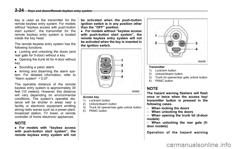
Access key
1) Lock/arm button
2) Unlock/disarm button
3) Trunk lid opener/rear gate unlock button
4) PANIC button
Transmitter
1) Lock/arm button
2) Unlock/disarm button
3) Trunk lid opener/rear gate unlock button
4) PANIC button
NOTE
The hazard warning flashers will flash
once or twice when the access key/
transmitter button is pressed in the
following cases.
– When locking the doors
– When unlocking the doors
– When opening the trunk lid (4-door
models)
– When unlocking the rear gate (5-
door models)
Operation of the hazard warning
2-24
Page 151 of 594
Instruments and controls/Push–button ignition switch (models with push –button start system)
& Ignition switch light (if
equipped)
For easy access to the ignition switch in
the dark, the ignition switch light illumi-
nates when the driver ’s door is opened or
when the driver ’s door is unlocked using
the remote keyless entry transmitter.
The light remains illuminated for several
tens of seconds and then gradually turns
off under the following conditions.
. when the driver ’s door is closed
. when the doors are unlocked using the
remote keyless entry transmitter
The light turns off immediately under the
following conditions.
. when the ignition switch is turned to the
“ ON ”position
. when all doors and the rear gate (5-
door) are locked using the remote keyless
entry transmitter
Push-button ignition switch
(models with push-button
start system)
& Safety precautions
Refer to “Safety precautions” F2-10.
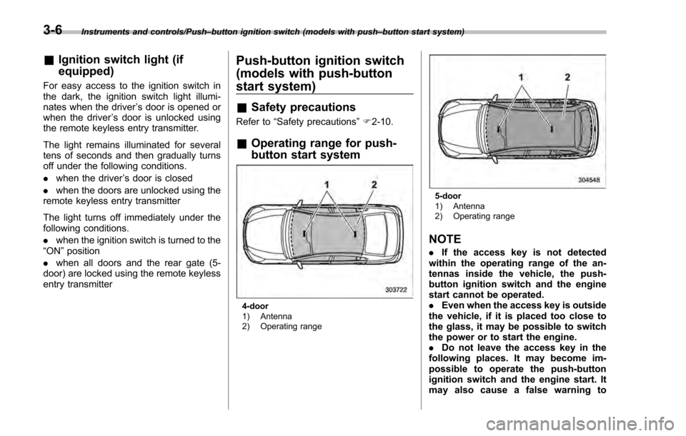
& Operating range for push-
button start system
4-door
1) Antenna
2) Operating range
5-door
1) Antenna
2) Operating range
NOTE
. If the access key is not detected
within the operating range of the an-
tennas inside the vehicle, the push-
button ignition switch and the engine
start cannot be operated.
. Even when the access key is outside
the vehicle, if it is placed too close to
the glass, it may be possible to switch
the power or to start the engine.
. Do not leave the access key in the
following places. It may become im-
possible to operate the push-button
ignition switch and the engine start. It
may also cause a false warning to
3-6
Page 184 of 594
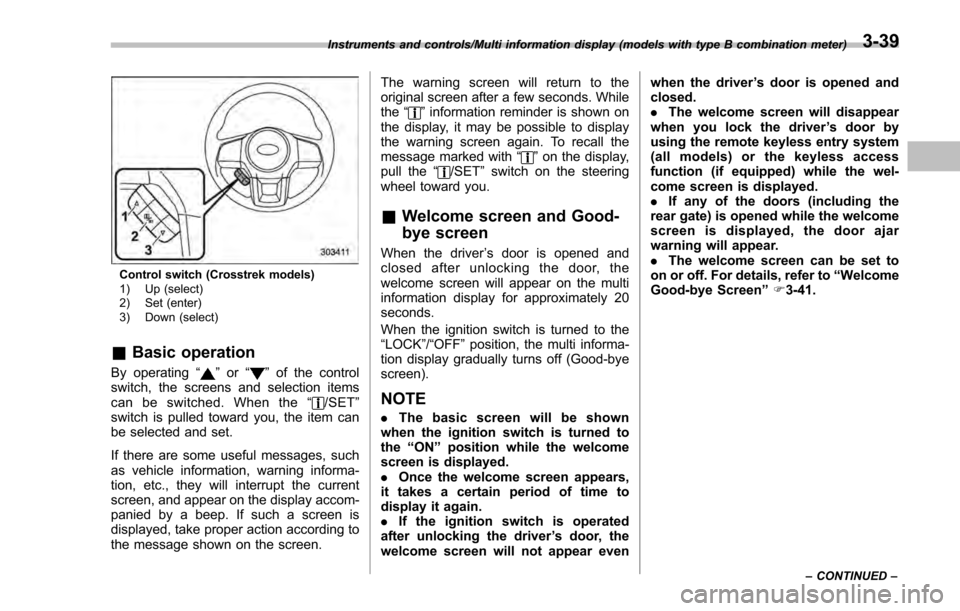
Control switch (Crosstrek models)
1) Up (select)
2) Set (enter)
3) Down (select)
&Basic operation
By operating “”or “”of the control
switch, the screens and selection items
can be switched. When the “
/SET”
switch is pulled toward you, the item can
be selected and set.
If there are some useful messages, such
as vehicle information, warning informa-
tion, etc., they will interrupt the current
screen, and appear on the display accom-
panied by a beep. If such a screen is
displayed, take proper action according to
the message shown on the screen. The warning screen will return to the
original screen after a few seconds. While
the
“
”information reminder is shown on
the display, it may be possible to display
the warning screen again. To recall the
message marked with “
”on the display,
pull the “/SET”switch on the steering
wheel toward you.
& Welcome screen and Good-
bye screen
When the driver ’s door is opened and
closed after unlocking the door, the
welcome screen will appear on the multi
information display for approximately 20
seconds.
When the ignition switch is turned to the
“LOCK”/ “OFF”position, the multi informa-
tion display gradually turns off (Good-bye
screen).
NOTE
. The basic screen will be shown
when the ignition switch is turned to
the “ON ”position while the welcome
screen is displayed.
. Once the welcome screen appears,
it takes a certain period of time to
display it again.
. If the ignition switch is operated
after unlocking the driver ’s door, the
welcome screen will not appear even when the driver
’s door is opened and
closed.
. The welcome screen will disappear
when you lock the driver ’s door by
using the remote keyless entry system
(all models) or the keyless access
function (if equipped) while the wel-
come screen is displayed.
. If any of the doors (including the
rear gate) is opened while the welcome
screen is displayed, the door ajar
warning will appear.
. The welcome screen can be set to
on or off. For details, refer to “Welcome
Good-bye Screen ”F 3-41.
Instruments and controls/Multi information display (models with type B combination meter)
–CONTINUED –3-39
Page 235 of 594

Instruments and controls/Light control switch
“”position: auto on/off headlights (if
equipped)
When the ignition switch is in the “ON ”
position, the instrument panel illumination,
headlights, parking lights, front side mar-
ker lights, rear side marker lights, tail lights
and license plate lights are automatically
on or off depending on the level of the
ambient light.
“
” position
The headlights are all off.
NOTE
The sensitivity of the auto on/off head-
lights can be changed by a SUBARU
dealer. Consult your SUBARU dealer
for details. Also, for models with a multi
function display, the setting can be
changed using the display. For details,
refer to “Auto light sensor sensitivity
setting ”F 3-83.
! Welcome lighting function (if
equipped)
The welcome lighting function turns on the
low beam headlight for smooth approach-
ing to or exiting from the vehicle at night or
in a dark place.
The function is activated while all of the
following conditions are met.
. The light control switch is in the “AUTO
”position
. It is dark enough to turn on the auto on/
off headlights
When approaching:
While the welcome lighting function is
activated, the low beam headlights will
automatically illuminate when unlocking
the doors (for 5-door, including the rear
gate) by using the remote keyless entry
system.
The low beam headlights will remain
illuminated for 30 seconds
*1and then turn
off. However, if any of the following
operations is done, the low beam head-
lights will turn off.
. The doors are locked.
. The light control switch is turned to a
position other than “AUTO”.
. The ignition switch is turned to the “ON”
position.
When exiting:
While the welcome lighting function is
activated, the low beam headlights will
remain illuminated even when either of the
following operation is done.
. Thepush-buttonignitionswitchis
turned to the “OFF”status (models with
“keyless access with push-button start
system ”) .
The key is pulled out from the ignition
switch (models without “keyless access
with push-button start system ”)
The low beam headlights will turn off
under any of the following conditions.
. 3 minutes have passed since the low
beam headlights were illuminated by the
welcome lighting function.
. 30 seconds have passed since the
door is opened and closed.
*1
. The light control switch is turned to a
position other than “AUTO”.
. The locking procedure is performed
twice. When performing the unlocking
procedure after performing the locking
procedure, perform the locking procedure
twice again.
*1: The setting for the period of time in which
the low beam headlights remain on by the
welcome lighting function can be changed by a
SUBARU dealer. Contact your SUBARU dealer
for details.
3-90
Page 248 of 594
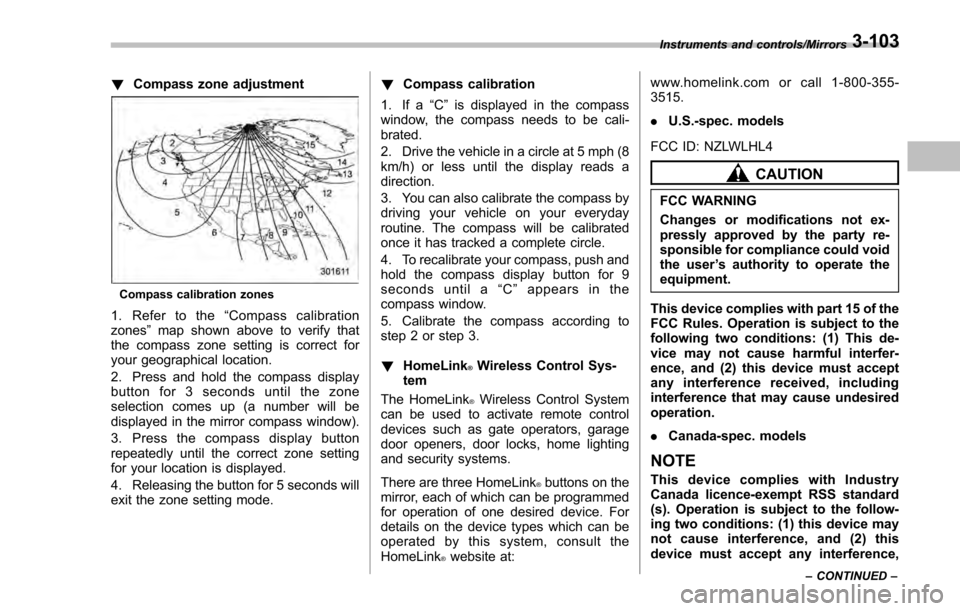
!Compass zone adjustment
Compass calibration zones
1. Refer to the “Compass calibration
zones” map shown above to verify that
the compass zone setting is correct for
your geographical location.
2. Press and hold the compass display
button for 3 seconds until the zone
selection comes up (a number will be
displayed in the mirror compass window).
3. Press the compass display button
repeatedly until the correct zone setting
for your location is displayed.
4. Releasing the button for 5 seconds will
exit the zone setting mode. !
Compass calibration
1. If a “C”is displayed in the compass
window, the compass needs to be cali-
brated.
2. Drive the vehicle in a circle at 5 mph (8
km/h) or less until the display reads a
direction.
3. You can also calibrate the compass by
driving your vehicle on your everyday
routine. The compass will be calibrated
once it has tracked a complete circle.
4. To recalibrate your compass, push and
hold the compass display button for 9
seconds until a “C ” appears in the
compass window.
5. Calibrate the compass according to
step 2 or step 3.
! HomeLink
®Wireless Control Sys-
tem
The HomeLink
®Wireless Control System
can be used to activate remote control
devices such as gate operators, garage
door openers, door locks, home lighting
and security systems.
There are three HomeLink
®buttons on the
mirror, each of which can be programmed
for operation of one desired device. For
details on the device types which can be
operated by this system, consult the
HomeLink
®website at: www.homelink.com or call 1-800-355-
3515.
.
U.S.-spec. models
FCC ID: NZLWLHL4
CAUTION
FCC WARNING
Changes or modifications not ex-
pressly approved by the party re-
sponsible for compliance could void
the user ’s authority to operate the
equipment.
This device complies with part 15 of the
FCC Rules. Operation is subject to the
following two conditions: (1) This de-
vice may not cause harmful interfer-
ence, and (2) this device must accept
any interference received, including
interference that may cause undesired
operation.
. Canada-spec. models
NOTE
This device complies with Industry
Canada licence-exempt RSS standard
(s). Operation is subject to the follow-
ing two conditions: (1) this device may
not cause interference, and (2) this
device must accept any interference,
Instruments and controls/Mirrors
–CONTINUED –3-103
Page 252 of 594
6. When the indicator light flashes slowly
and then rapidly after several seconds,
release both buttons.
7. Plug the motor of the entrance gate/
garage door opener to the outlet.
8. Test your entrance gate/garage door
opener by pressing the programmed
HomeLink
®button.
! Operating the HomeLink
®Wire-
less Control System
Once programmed, the HomeLink
®Wire-
less Control System can be used to
remote-control the devices to which its
buttons are programmed. To activate a
device, simply press the appropriate but-
ton. The indicator light illuminates, indicat-
ing that the signal is being transmitted.
!Programming other devices
To program other devices such as door
locks, home lighting and security systems,
contact HomeLink
®at www.homelink.com
or call 1-800-355-3515.
! Reprogramming a single
HomeLink
®button
1. Press and hold the HomeLink
®button
you wish to reprogram. DO NOT release
the button until step 4 has been com-
pleted.
2. When the HomeLink
®indicator light begins to flash slowly (after approximately
20 seconds), position the hand-held trans-
mitter of the device between 1 to 3 inches
(25 to 76 mm) away from the HomeLink
®button you wish to program.
3. Press and hold the hand-held trans-
mitter button. The HomeLink
®indicator
light will flash, first slowly and then rapidly.
4. When the indicator light begins to flash
rapidly, release both buttons.
The programming for the previous device
is now erased and the new device can be
operated by pressing the HomeLink
®button.
!Erasing HomeLink
®button mem-
ory
NOTE
. Performing this procedure erases
the memory of all the preprogrammed
buttons simultaneously. The memory
of individual buttons cannot be erased.
. It is recommended that upon the
sale of the vehicle, the memory of all
programmed HomeLink
®buttons be
erased for security purposes.
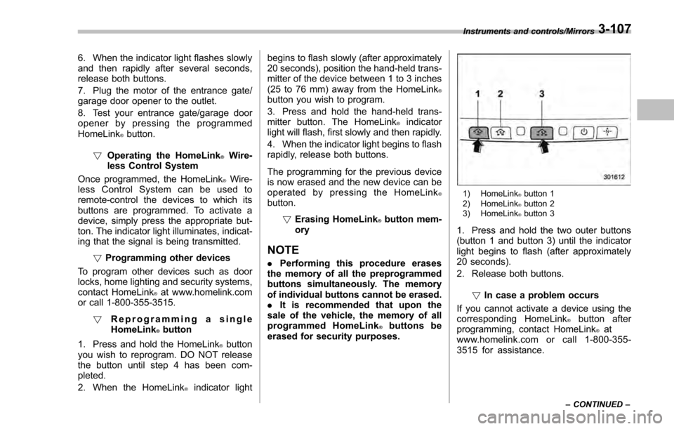
1) HomeLink®button 1
2) HomeLink®button 2
3) HomeLink®button 3
1. Press and hold the two outer buttons
(button 1 and button 3) until the indicator
light begins to flash (after approximately
20 seconds).
2. Release both buttons.
!In case a problem occurs
If you cannot activate a device using the
corresponding HomeLink
®button after
programming, contact HomeLink®at
www.homelink.com or call 1-800-355-
3515 for assistance.
Instruments and controls/Mirrors
–CONTINUED –3-107
Page 253 of 594
Instruments and controls/Defogger and deicer
&Outside mirrors
! Convex mirror (passenger side)
WARNING
Objects look smaller in a convex
mirror and farther away than when
viewed in a flat mirror. Do not use
the convex mirror to judge the
distance of vehicles behind you
when changing lanes. Use the inside
mirror (or glance backwards) to
determine the actual size and dis-
tance of objects that you view in
convex mirror. !
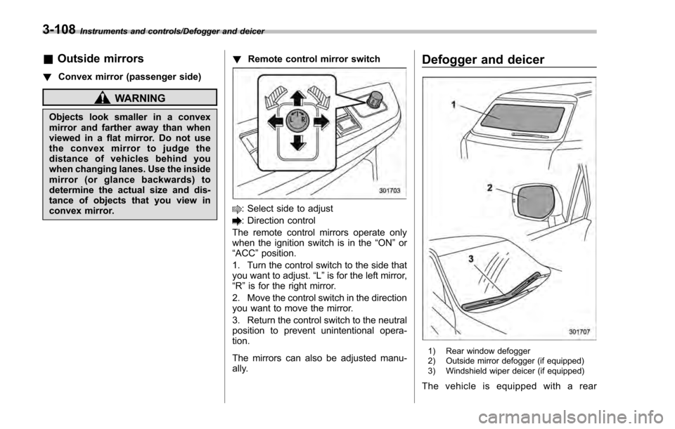
Remote control mirror switch
: Select side to adjust
: Direction control
The remote control mirrors operate only
when the ignition switch is in the “ON”or
“ACC ”position.
1. Turn the control switch to the side that
you want to adjust. “L”is for the left mirror,
“R ”is for the right mirror.
2. Move the control switch in the direction
you want to move the mirror.
3. Return the control switch to the neutral
position to prevent unintentional opera-
tion.
The mirrors can also be adjusted manu-
ally.
Defogger and deicer
1) Rear window defogger
2) Outside mirror defogger (if equipped)
3) Windshield wiper deicer (if equipped)
The vehicle is equipped with a rear
3-108
Page 386 of 594

Fuel...................................................................... 7-3Fuel requirements ............................................... 7-3
Fuel filler lid and cap ........................................... 7-4
State emission testing (U.S. only) ...................... 7-7
Preparing to drive ............................................... 7-8
Starting and stopping the engine (models without push-button start system) .................. 7-9
Starting engine.................................................... 7-9
Stopping the engine ........................................... 7-11
Starting and stopping engine (models with
push-button start system) .............................. 7-12
Safety precautions............................................. 7-12
Operating range for push-button start system ............................................................. 7-12
Starting engine ................................................... 7-12
Stopping engine ................................................. 7-13
When access key does not operate properly ....... 7-14
Remote engine start system (dealer
option) .............................................................. 7-14
Models with “keyless access with push-button
start system ”................................................... 7-15
Models without “keyless access with push-button
start system ”................................................... 7-16
Entering the vehicle while it is running via remote start ................................................................. 7-19
Entering the vehicle following remote engine start shutdown ......................................................... 7-19
Pre-heating or pre-cooling the interior of the vehicle ............................................................. 7-19
Service mode (models without “keyless access
with push-button start system ”)........................ 7-19 Remote transmitter program (models without
“keyless access with push-button start
system ”).......................................................... 7-19
System maintenance .......................................... 7-20
Manual transmission ......................................... 7-22Shifting speeds.................................................. 7-22
Driving tips ........................................................ 7-23
Continuously variable transmission ................. 7-23Continuously variable transmission features . ..... 7-24
Select lever ....................................................... 7-24
Selection of manual mode (if equipped) .............. 7-26
Selection of “L”(if equipped) ... .......................... 7-28
Shift lock function ............................................. 7-28
Driving tips ........................................................ 7-29
Power steering ................................................... 7-30Power steering warning light .............................. 7-30
Power steering system features ......................... 7-30
Braking............................................................... 7-31Braking tips ....................................................... 7-31
Brake system .................................................... 7-31
Disc brake pad wear warning indicators ............. 7-32
ABS (Anti-lock Brake System).......................... 7-32ABS self-check.................................................. 7-32
ABS warning light .............................................. 7-33
Electronic Brake Force Distribution (EBD)
system ............................................................. 7-33
Steps to take if EBD system malfunctions .......... 7-33
Vehicle Dynamics Control system.................... 7-34Safety precautions............................................. 7-34
System features ................................................. 7-35
Vehicle Dynamics Control system monitor .......... 7-36
Starting and operating
7