Page 145 of 172

Replacing windscreen wiper blades
Introduction
This chapter contains information on the following subjects:
Replacing the windscreen wiper blades
143
Replacing the rear window wiper blade
143WARNINGReplace the windscreen wiper blades once or twice a year for safety rea-
sons.
Replacing the windscreen wiper blades
Fig. 161
Setting the service position for
the wiper arms
Fig. 162
Changing the front windscreen wiper blade
Read and observe
on page 143 first.
Before replacing the windscreen wiper blades, close the bonnet and put the windscreen wiper arms into the service position.
Setting the service position›Switch the ignition on and off again.›
Push the lever in the direction of arrow » Fig. 161 within 10 seconds and hold
for approximately 2 seconds.
Removing the wiper blade
›
Lift the wiper arm from the windscreen in the direction of arrow
1
» Fig. 162 .
›
Tilt the wiper blade as far as it will go in the same direction.
›
Grip the wiper arm and press securing latch
A
down in the direction of arrow
2
.
›
Remove the wiper blade in the direction of the arrow
3
.
Attaching the windscreen wiper blade
›
Slide the windscreen wiper blade in the opposite direction to arrow
3
until it
locks into place. Check that the windscreen wiper blade is correctly attached.
›
Fold the windscreen wiper arm back to the windscreen.
›
Turn on the ignition and press the lever in the direction of the arrow
» Fig. 162 .
The windscreen wiper arms move into the home position.
Replacing the rear window wiper blade
Fig. 163
Changing the rear window wiper blade
Read and observe
on page 143 first.
Removing the wiper blade
›
Lift the wiper arm » page 143 from the window in the direction of arrow
1
» Fig. 163.
›
Tilt the wiper blade as far as it will go in the same direction.
›
Grip the wiper arm and press securing latch
A
down in the direction of arrow
2
.
143Emergency equipment and self-help
Page 146 of 172

›Remove the wiper blade in the direction of the arrow 3.
Attaching the windscreen wiper blade›
Slide the windscreen wiper blade in the opposite direction to arrow
3
until it
locks into place. Check that the windscreen wiper blade is correctly attached.
›
Fold the windscreen wiper arm back to the windscreen.
Fuses and light bulbs
Fuses
Introduction
Fig. 164
Blown fuse
This chapter contains information on the following subjects:
Fuses in the dash panel
145
Fuse arrangement in the dash panel
145
Fuses on the side of the dash panel
146
Assignment of the fuses on the side of the dash panel
146
Fuses in the engine compartment
147
Fuse arrangement in the engine compartment
147
Individual electrical circuits are protected by fuses. A blown fuse is recognisa-
ble from the melted-through metal strip » Fig. 164.
WARNINGAlways read and observe the warnings before completing any work in the
engine compartment » page 120.
CAUTION
■
Replace the faulty fuse with a new one of the same amperage.■If a newly inserted fuse again blows after a short time, then seek assistance
from a specialist garage.■
“Do not repair” the fuses and do not replace them with stronger fuses - dan-
ger of fire and damage to another electrical system.
144Do-it-yourself
Page 147 of 172

Note■We recommend always carrying replacement fuses in the vehicle.■There can be several power consuming devices for one fuse. Multiple fuses
may exist for a single power consuming device.
Fuses in the dash panel
Fig. 165
Remove the fuse box cover.
Read and observe and on page 144 first.
The fuses are located underneath the steering wheel on the underside of the
dash panel » Fig. 165.
Replacing fuses
›
Remove the ignition key, turn off the lights and all electrical consumers.
›
Press securing tab
A
» Fig. 165 .
›
Push the lid in the direction of the arrow.
›
Remove bracket
B
.
›
Use the clip to pull the fuse out, then insert a new fuse.
›
Replace the bracket at the original position.
›
Close the cover in the opposite direction to the arrow until it clicks into place.
Fuse arrangement in the dash panel
Fig. 166
Fuses
Read and observe and on page 144 first.No.Consumer1Air Conditioning, diagnostic connector2Operating the headlight range control, parking aid, adjusting the mir-
ror surface with electric exterior mirrors3Automatic transmission, engine control unit, power steering, control
lever under the steering wheel, instrument cluster4Airbag5Reversing light6Rear wiper, front and rear window washer7Main beam headlamp - left side8Main beam headlamp - right side9Not assigned10Electric exterior mirror heater, diagnostic port11Not assigned12Vehicle lighting13Vehicle lighting14Vehicle lighting15Vehicle with START-STOPsystem: Radio
Vehicle without START-STOPsystem: Lighting of switches, heating,
automatic transmission, light switch, license plate light16Vehicle lighting17Rear window wiper18Panoramic roof19Central locking system20Rear window heating21Reversing light22Horn23Voltage stabiliser (for START-STOP system)24Headlamp flasher25Windscreen wipers26Radio27Turn signal lights, brake lights 145Fuses and light bulbs
Page 148 of 172

No.Consumer28Selector lever for the automatic transmission29Fuel pump30Engine control unit, instrument cluster, rain sensor, control lever un-
der the steering wheel31Vehicle lighting32Central control system33Vehicle lighting34Interior lighting35Vehicle lighting36Vehicle lighting37ESC38Key bar39Control lever under the steering wheel, front and rear window wash- er40Lambda probe, radiator fan, gas valve, oil pressure valve, valve for
activated charcoal filter41Brake pedal switch, cooling fan42Engine control system43Fuel pump44Injection valves45Ignition coils4612 volt power socket47Air blower for air conditioning/heating48Seat heaters49Electric windows50Vehicle lighting51Electric power windowsFuses on the side of the dash panelFig. 167
Remove the fuse box cover.
Read and observe and on page 144 first.
On vehicles with the START-STOPsystem, the fuses are on the left side of the
dash panel behind a cover.
Replacing fuses
›
Remove the ignition key, turn off the lights and all electrical consumers.
›
Insert a slotted screwdriver into the recess
A
in the cover » Fig. 167.
›
Loosen the cover and remove in the direction of the arrow.
›
Replace the defective fuse.
›
Press down on the cover until it clicks into place.
Assignment of the fuses on the side of the dash panel
Fig. 168
Fuses
Read and observe and on page 144 first.
No.Consumer1ABS/ESP2Instrument cluster 146Do-it-yourself
Page 149 of 172

No.Consumer3Radio4DC-DC voltage converter, motor starter, bar with buttons5Air conditioning system6Not assigned7Not assigned8Not assigned9Vehicle lighting - right side10Vehicle lighting - left side11Starter12DC-DC voltage converter, ABS, instrument cluster, radio
Fuses in the engine compartment
Fig. 169
Remove the fuse box cover.
Read and observe and on page 144 first.
The fuses are located underneath a cover next to the vehicle battery
» Fig. 169 .
Replacing fuses
›
Remove the ignition key, turn off the lights and all electrical consumers.
›
Press the locking keys
1
of the cover » Fig. 169 together simultaneously.
›
Push the cover in the direction of the arrow
2
.
›
Replace the defective fuse.
›
Position the cover against the arrow until it clicks.
Fuse arrangement in the engine compartmentFig. 170
Fuses
Read and observe and on page 144 first.
No.Consumer1ABS/ESP2Radiator fan3Cooling control system, ignition4ABS/ESP5Battery data module6Ignition lock, starter
Bulbs
Introduction
This chapter contains information on the following subjects:
Bulb arrangement in the front headlights
148
Removing bulbs for low and high beam- Variant 1
148
Replacing the bulb for daytime running lights and parking lights- Variant
1
149
Change bulb for low beam and high beam - Variant 2
149
Changing the bulb for the front turn signal light
149
Changing light bulbs for fog lights
150
Changing the bulb for the licence plate light
150
Removing/installing taillights
151
Replacing the bulbs in the tail lamp assembly
151
147Fuses and light bulbs
Page 150 of 172

We recommend having bulbs replaced by a specialist garage or seeking other
expert help in the event of any uncertainties.
▶ Switch off the ignition and all of the lights before replacing a bulb.
▶ Faulty bulbs must only be replaced with the same type of bulbs. The designa-
tion is located on the light socket or the glass bulb.
We recommend having the headlight settings checked by a specialist garage after replacing a bulb in the low or high beam unit or the fog lamp.
Visit a specialist garage if an LED diode is faulty.WARNING■ Always read and observe the warnings before completing any work in the
engine compartment » page 120.■
Accidents can be caused if the road in front of the vehicle is not suffi-
ciently illuminated and the vehicle cannot or can only be seen with difficul-
ty by other road users.
■
Bulbs H4, HB4 and H7 are pressurised and may burst when changed –
There is a risk of injury! We therefore recommended wearing gloves and
safety glasses when changing a bulb.
CAUTION
Do not take hold of the glass bulb with naked fingers (even the smallest
amount of dirt reduces the working life of the light bulb). Use a clean cloth,
napkin, or similar.
Note
■ This Owner's Manual only describes the replacement of bulbs where it is pos-
sible to replace the bulbs on your own without any complications arising. Other
bulbs must be replaced by a specialist garage.■
We recommend that a box of replacement bulbs always be carried in the ve-
hicle.
Bulb arrangement in the front headlightsFig. 171
Variant 1/Variant 2
Read and observe
and on page 148 first.
Bulb arrangement » Fig. 171
Flashing
Low beam and high beam
Daytime running and parking light
Low beam
High beam
Removing bulbs for low and high beam- Variant 1
Fig. 172
Removing bulbs for low and main beam
Read and observe
and on page 148 first.
›
Remove the connector from the bulb in the direction of arrow
1
» Fig. 172 .
›
Remove the protective cap
A
.
ABCDE148Do-it-yourself
Page 151 of 172

›Press the safety catch in the direction of the headlamp and then unhook in
the direction of arrow 2 » Fig. 172 .›
Open out the safety catch in the direction of arrow
3
.
›
Remove the light bulb in the direction of arrow
4
and insert a new light bulb
in such a way that the fixing lugs of the light bulb socket fit into the recesses
of the lamp.
Insertion of the bulb takes place in reverse order.
Replacing the bulb for daytime running lights and parking lights-
Variant 1
Fig. 173
Replacing the bulb for daytime
running lights and parking lights
Read and observe and on page 148 first.
›
Turn the housing containing the bulb
C
» Fig. 171 on page 148 as far as the
stop in the direction of the arrow
1
» Fig. 173 .
›
Remove the housing containing the bulb in the direction of arrow
2
.
›
Change the bulb.
›
Insert the housing containing the light bulb in the lamp housing in the oppo-
site direction to arrow
2
.
›
Screw the housing in the opposite direction to arrow
1
until it clicks into
place.
Change bulb for low beam and high beam - Variant 2Fig. 174
Removing bulbs for high and
main beam
Read and observe and on page 148 first.
›
Remove the protective caps
D
and
E
» Fig. 171 on page 148 .
›
Turn the holder with the bulb in the direction of arrow
1
» Fig. 174 .
›
Remove the holder with the bulb in the direction of arrow
2
.
›
Change the bulb and insert the connector with the new bulb into the head-
light in the opposite direction to the arrow
2
.
›
Turn the connector with the new bulb in the opposite direction to the arrow
1
until it stops.
›
Use the protective caps
D
and
E
» Fig. 171 on page 148 .
Changing the bulb for the front turn signal light
Fig. 175
Change bulb for front indicator: Variant 1 / Variant 2
Read and observe
and on page 148 first.
›
Turn the socket with the bulb to the stop in the direction of the arrow
1
» Fig. 175 .
›
Remove the housing containing the bulb in the direction of arrow
2
.
149Fuses and light bulbs
Page 152 of 172

›Unscrew the defective bulb in its housing in an
anti-clockwise direction and
remove it.›
Place a new bulb in the housing and turn it in a clockwise direction as far as
it will go.
›
Insert the housing containing the light bulb in the lamp housing in the oppo-
site direction to arrow
2
.
›
Screw the housing in the opposite direction to arrow
1
until it clicks into
place.
Changing light bulbs for fog lights
Fig. 176
Remove wheel arch trim
Fig. 177
Changing a bulb
Read and observe
and on page 148 first.
Remove wheel arch trim
›
Use the on board tool to remove screws
A
» Fig. 176 from the wheel well.
›
Using a flat, blunt object (e.g. a coin) turn the part of the expansion rivet with
a slit a quarter of a turn in the direction of arrow
1
.
› Pull out the part of the expansion rivet with a slit in the direction of arrow2 .›
Take out the expansion rivet in the direction of the arrow
3
.
Changing a bulb
›
Open out the wheel house trim in the direction of arrow
4
» Fig. 177 .
›
Press the latch on the connector in the direction of arrow
5
.
›
Remove the connector in the direction of the arrow
6
.
›
Turn the socket with the bulb to the stop in the direction of the arrow
7
.
›
Remove the socket with the bulb in the direction of arrow
8
.
›
Place a new connector with the bulb in the headlamp and turn it in the direc-
tion of arrow
7
as far as the stop.
›
Attach the connector until it clicks firmly into place.
Insert wheel arch cover
›
Fold the wheel house trim back.
›
Push in the part of the expansion rivet with a slit
2
and turn it a quarter of
one turn in the opposite direction to arrow
1
» Fig. 176 .
›
Firmly tighten the two attachment bolts
A
with the screwdriver.
Changing the bulb for the licence plate light
Fig. 178
Remove licence plate light
Read and observe
and on page 148 first.
›
Insert a slotted screwdriver into the slot in area
A
» Fig. 178 and free up the
lamp in the direction of arrow
1
.
›
Remove the lamp from the bumper.
›
Unscrew the lamp in the direction of arrow
2
and remove it in the direction
of arrow
3
.
›
Change the bulb.
150Do-it-yourself
 1
1 2
2 3
3 4
4 5
5 6
6 7
7 8
8 9
9 10
10 11
11 12
12 13
13 14
14 15
15 16
16 17
17 18
18 19
19 20
20 21
21 22
22 23
23 24
24 25
25 26
26 27
27 28
28 29
29 30
30 31
31 32
32 33
33 34
34 35
35 36
36 37
37 38
38 39
39 40
40 41
41 42
42 43
43 44
44 45
45 46
46 47
47 48
48 49
49 50
50 51
51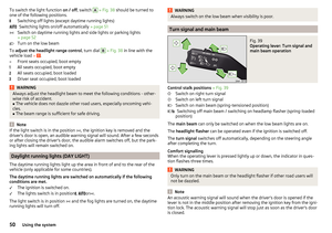 52
52 53
53 54
54 55
55 56
56 57
57 58
58 59
59 60
60 61
61 62
62 63
63 64
64 65
65 66
66 67
67 68
68 69
69 70
70 71
71 72
72 73
73 74
74 75
75 76
76 77
77 78
78 79
79 80
80 81
81 82
82 83
83 84
84 85
85 86
86 87
87 88
88 89
89 90
90 91
91 92
92 93
93 94
94 95
95 96
96 97
97 98
98 99
99 100
100 101
101 102
102 103
103 104
104 105
105 106
106 107
107 108
108 109
109 110
110 111
111 112
112 113
113 114
114 115
115 116
116 117
117 118
118 119
119 120
120 121
121 122
122 123
123 124
124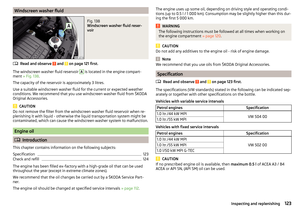 125
125 126
126 127
127 128
128 129
129 130
130 131
131 132
132 133
133 134
134 135
135 136
136 137
137 138
138 139
139 140
140 141
141 142
142 143
143 144
144 145
145 146
146 147
147 148
148 149
149 150
150 151
151 152
152 153
153 154
154 155
155 156
156 157
157 158
158 159
159 160
160 161
161 162
162 163
163 164
164 165
165 166
166 167
167 168
168 169
169 170
170 171
171