Page 105 of 172
 it can cause serious damage to the vehicle!■
Oncoming vehicles can generate water waves which can e")
CAUTION■If water gets into the vehicle’s systems (e.g. the air intake system for the en-
gine) it can cause serious damage to the vehicle!■
Oncoming vehicles can generate water waves which can exceed the permis-
sible water level for your vehicle.
■
Do not drive through salt water, as the salt can cause corrosion. An vehicle
coming into contact with salt water is to be thoroughly rinsed with fresh wa-
ter.
Assist systems
General information
Introduction
WARNING■
The assistance systems serve merely to support the driver and do not re-
lieve the driver of responsibility for the operation of the vehicle.■
The increased safety as well as the increased occupant protection offered
by the assistance systems must not tempt you to take safety risks - there
is a risk of an accident!
■
Adjust the speed and driving style to the current visibility, weather, road
and traffic conditions.
■
The assistance systems have physical and system-related limitations. For
this reason, the driver may experience some undesired or delayed system
responses in certain situations. You should therefore always be alert and
ready to intervene!
■
Only activate, deactivate and set the assistance systems to keep you fully
in control of the vehicle in every traffic situation - otherwise there is a risk
of an accident!
Braking and stabilisation systems
Introduction
This chapter contains information on the following subjects:
Stability Control (ESC)
104
Anti-lock braking system (ABS)
104
Engine drag torque control (MSR)
104
Traction control (TCS)
104
Electronic Differential Lock (EDL)
104
Brake Assist (HBA)
104
Hill Start Assist (HHC)
104
The brake and stabilisation systems are automatically activated each time the
ignition is switched on, unless otherwise indicated.
The error display is in Chapter » page 31, Warning lights .
103Assist systems
Page 106 of 172

Read and observe
on page 104 first.
The ES")
WARNINGThe general information relating to the use of assistance systems must be
observed » page 103, in section Introduction .
Stability Control (ESC)
Read and observe
on page 104 first.
The ESC improves vehicle stability when driving at the limit (e.g. if the vehiclestarts to skid) by braking individual wheels to maintain the desired direction.
If there is a TCS intervention, the indicator light flashes in the instrument
cluster.
Anti-lock braking system (ABS)
Read and observe
on page 104 first.
ABS prevents the wheels locking when braking. Thus helping the driver to
maintain control of the vehicle.
The intervention of the ABS is noticeable from the pulsating movements of
the brake pedal which is accompanied by noises.
When the ABS system is active, do not brake periodically or reduce the pres-
sure on the brake pedal.
Engine drag torque control (MSR)
Read and observe
on page 104 first.
MSR counteracts the tendency of the drive wheels to lock during downshifts
or sudden deceleration (e.g. on icy or an otherwise slippery road surface).
If the drive wheels should lock, then the engine speed is automatically in-
creased. This reduces the braking effect of the engine and the wheels can ro-
tate freely again.
Traction control (TCS)
Read and observe
on page 104 first.
TCS prevents the spinning of the wheels on the drive axle. TCS reduces the
drive power transmitted to the wheels that are spinning. Thus, for example,
driving on road surfaces with low grip is made easier.
If there is a TCS intervention, the warning light flashes in the instrument
cluster.
Electronic Differential Lock (EDL)
Read and observe
on page 104 first.
EDL prevents the turning of the respective wheel of the driven axle. EDL
brakes a spinning wheel if required and transfers the drive power force to the
other drive wheel. Driving becomes easier on road surfaces with different trac-
tion under each wheel of the driven axle.
The EDL switches off automatically in order to avoid excessive heat generation
on the brake of the wheel being braked. Once the brakes have cooled down,
there is an automatic re-activation of EDL.
Brake Assist (HBA)
Read and observe
on page 104 first.
HBA increases the braking effect and helps to shorten the braking distance.The HBA is activated by very quick operation of the brake pedal. In order to
achieve the shortest possible braking distance, the brake pedal must be ap-
plied firmly until the vehicle has come to a standstill.
The HBA function is automatically switched off when the brake pedal is re-
leased.
Hill Start Assist (HHC)
Read and observe
on page 104 first.
When moving off on a gradient, HHC allows you to move your foot from thebrake pedal to the accelerator pedal without the vehicle rolling downhill.
The vehicle is braked by the system for about 2 seconds after releasing the
brake pedal.
The HHC is active on gradients upwards up 5 % if the driver door is closed. HHC
is always only active on slopes when in forward or reverse start off.
104Driving
Page 107 of 172

Introduction
This chapter contains information on the following subjects:
Function
105
Display in the swing radio display
106
The parking aid (hereinafter referred to only a")
Parking aid (ParkPilot)
Introduction
This chapter contains information on the following subjects:
Function
105
Display in the swing radio display
106
The parking aid (hereinafter referred to only as a system) draws attention via
acoustic signals and an indication in the swing radio when manoeuvring
around obstacles in the vicinity of the vehicle.
WARNING■ The general information relating to the use of assistance systems must
be observed » page 103, in section Introduction .■
Moving persons or objects may not be recognized by the system sensors.
■
Under certain circumstances, surfaces of certain objects and types of
clothing cannot reflect the system signals. There is a danger that such ob-
jects or people may not be recognised by the system sensors.
■
External noise sources may affect the signals of the system sensors.
There is a danger that obstacles may not be recognised by the system sen-
sors.
■
Before reversing, you should make sure that there are no small obstacles
- such as rocks, small posts or similar - behind your vehicle. Such obstacles
may not be recognised by the system sensors.
CAUTION
■ Keep the system sensors » Fig. 125 on page 105 clean and free from snow
and ice, and do not cover them with any objects of any kind, otherwise the
functioning of the system may be restricted.■
In adverse weather conditions (heavy rain, water vapour, very low or high
temperatures, etc.), the functioning of the system may be impaired - “incorrect
recognition of obstacles”.
■
Accessories additionally installed on the vehicle rear, such as bicycle carriers,
can impair the system function.
FunctionFig. 125
Fitting the sensors / Range of the sensors
Read and observe
and on page 105 first.
The system uses ultrasound waves to calculate the distance between the
bumper and an obstacle. The ultrasonic sensors are integrated in the rear
bumper » Fig. 125 .
Approximate range of sensors » Fig. 125
150 cm
60 cm
Audible signals
The interval between the acoustic signals becomes shorter as the clearance is
reduced. At a distance of approx. 30 cm a continuous tone starts to sound -
danger area. From this moment do not continue to move towards the obsta-
cle!
Activation/deactivation
The system is activated by engaging reverse gear. When activated an audible
signal is heard.
The system is deactivated by disengaging reverse gear.
Fault display
If a warning signal sounds for 3 seconds after activating the system and there
is no obstacle close to your car, this indicates a system fault. Seek help from a
specialist garage.
AB105Assist systems
Page 108 of 172

Display in the swing radio displayFig. 126
Function keys and dis-
play
Read and observe and on page 105 first.
Function keys and display » Fig. 126Switching audible parking signals on/off.Switching off park assistant display.There is an obstacle in the collision area (the distance to the obstacle
is less than 30 cm).
Stop moving in the direction of the obstacle!An obstacle is located outside of the collision range (the distance to
the obstacle is greater than 30 cm).
Cruise Control System
Introduction
This chapter contains information on the following subjects:
Operation
106
Operation description
106
The Cruise Control System (CCS) maintains a set speed without you having to
actuate the accelerator pedal. The state where the GRA maintains the speed is
referred to hereinafter as the control.
WARNINGThe general information relating to the use of assistance systems must be
observed » page 103, in section Introduction .Operation
Read and observe
on page 106 first.
Basic requirements for start of control The GRA is activated.
On vehicles with a manual transmission , the second gear or higher is en-
gaged.
On vehicles with an automatic transmission , the selector lever is in the D
position or in the Tiptronic position.
The current speed is higher than 20 km/h.
This, however, is only possible to the extent permitted by the engine output
and braking power of the vehicle.
WARNINGIf the engine output or engine braking effect is insufficient to maintain the
set speed, the driver must assume control of the accelerator and brake
pedals!
Operation description
Fig. 127
Cruise control system controls
Read and observe on page 106 first.
Overview of the CCS controls » Fig. 127AActivate ACC (control deactivated) Interrupt control (sprung position) Deactivate CCS (delete set speed) 106Driving
Page 109 of 172

/ Increase speedCLaunch control / reduce speeda)
If no speed is set the current speed is adopted.
Once the controls are activated, the CCS maintain")
BTake control againa)
/ Increase speedCLaunch control / reduce speeda)
If no speed is set the current speed is adopted.
Once the controls are activated, the CCS maintains the vehicle at the set
speed; the indicator light
lights up in the instrument cluster.
After the interruption in control, the stored speed can be resumed by pressing
the
B
button.
Controls are automatically interrupted if any of the following occur.
▶ By pressing the brake or clutch pedal.
▶ When one of the brake assist systems (e.g. ESC) intervenes.
▶ Through an airbag deployment.
WARNING■ Always deactivate the cruise control system after use to prevent the sys-
tem being switched on unintentionally.■
Control may only be resumed if the set speed is not too high for the cur-
rent traffic conditions.
Note
During control, speed can be increased by pressing the accelerator pedal. Re-
leasing the accelerator pedal will cause the speed to drop again to the set
speed.
City Safe Drive
Introduction
This chapter contains information on the following subjects:
Operation
107
Disable / Enable
108
City Safe Drive (hereinafter referred to as: the system) monitors the traffic sit-
uation ahead of the vehicle. If the system detects a risk of collision with an ob-
stacle ahead of the vehicle, then automatic braking is applied. The risk of a col-
lision is thus reduced and the consequences of an impact are minimized.
WARNING■ The general information relating to the use of assistance systems must
be observed » page 103, in section Introduction .■
The system does not respond to crossing or oncoming objects.
CAUTION
The system can slow down the vehicle to a standstill. If the vehicle continues
to roll forward after stopping, then it should be stopped with the footbrake.
Operation
Fig. 128
Laser sensor/detection range
Read and observe
and on page 107 first.
By means of a laser sensor » Fig. 128 -
the system registers traffic situations
ahead of the vehicle up to a distance of about 10 metres » Fig. 128 -
.
The system interventions take place when a risk of collision is detected as fol- lows.
▶ The brake system is prepared for an emergency stop.
▶ If the driver fails to respond to a detected danger, an automatic braking ac-
tion is performed.
The system can intervene if the following basic conditions apply. The engine is running.
The system is activated.
The vehicle speed is about 5-30 km/h.
The field of view of the laser sensor is not impaired.
107Assist systems
Page 110 of 172
.
▶ Driving around “sharp” bends.
▶")
The system can, for example, be affected in the following situations or not
be available. ▶ When visibility is poor, (e.g. fog, heavy rain, thick snowfall).
▶ Driving around “sharp” bends.
▶ When fully pressing down the accelerator pedal.
▶ When the laser sensor is dirty or obscured.
▶ When the vehicles are very dirty and have a low level of reflection.
If the system is not available or there is a system malfunction, the message
and the warning light appears on the display of the instrument cluster
flashes in a slow sequence.WARNINGDo not cover the windscreen in the area of the laser sensor. This can lead
to impaired function of the sensor - risk of accidents!WARNINGThe laser beam from the laser sensor can cause serious eye injuries. The la-
ser beam is not visible to the human eye.■
Never use optical devices, e.g. a range-finder camera or magnifying glass
to look into the laser sensor.
■
The laser beam can also be active when the system is disabled or is not
available.
CAUTION
■ Remove any snow from the windscreen in the area of the laser sensor using
a hand brush and any ice with a solvent-free de-icing spray.■
If the laser sensor range on the windscreen has scratches, cracks, etc., re-
place the windscreen.
Note
■ If an automatic brake intervention is triggered by the system, the pressure in
the brake system increases and the brake pedal cannot be operated with the
normal pedal stroke.■
Automatic braking interventions by the emergency brake function can be ter-
minated by pressing the clutch or the accelerator or by moving the steering
wheel.
Disable / EnableFig. 129
Button for the City Safe Drive
system
Read and observe and on page 107 first.
The function is automatically activated each time the ignition is switched on.
›
to deactivate hold the button » Fig. 129 until a beep sounds.
The appropriate message and the indicator light appears
flashes several
times in a quicker sequence (the
lights up at a speed of 5-30 km / h).
›
To
activate hold the button » Fig. 129until a beep sounds.
The appropriate message and the warning light appears
in the display of
the instrument cluster.
WARNINGFor safety reasons, deactivate the system in the following situations.■When the vehicle is being towed away.■
When the vehicle is driven though an automatic car wash.
■
If the laser sensor is damaged or faulty.
■
When the vehicle is on a rolling test bench.
■
When the windscreen is damaged in the region of the laser sensor.
■
For example, if the charge extends to the roof rack over the front edge of
the roof.
Tyre pressure monitoring
Introduction
This chapter contains information on the following subjects:
Storing the tyre pressure values.
109
108Driving
Page 111 of 172

monitors the tyre pressure while driving.
If the tyre inflation pressure changes, the warning light
lights up in th")
The tyre pressure monitoring function (hereinafter referred to as: the system)
monitors the tyre pressure while driving.
If the tyre inflation pressure changes, the warning light
lights up in the in-
strument cluster and an audible signal is heard » page 34,
.
The system can only function properly if the tyres have the prescribed inflation pressure and these pressure values are stored in the system.WARNING■ The general information relating to the use of assistance systems must
be observed » page 103, in section Introduction .■
Having the correct tyre inflation pressure is always the driver's responsi-
bility. Tyre pressure should be checked regularly » page 129.
■
The system cannot warn in case of very rapid tyre inflation pressure loss,
e.g. in case of sudden tyre damage.
Storing the tyre pressure values.
Fig. 130
Key for storing the pressure val-
ues
Read and observe on page 109 first.
Procedure for storing the tyre pressure values
›
Inflate all the tyres to the specified pressure.
›
Switch on the ignition.
›
Press down
» Fig. 130 on the button.
The warning light
lights up in the instrument cluster.
An acoustic signal and the control indicator provide information about the
storage of the tyre pressure values.
›
Release
.
Always save the tyre pressure values in the system if one of the following
events occurs.
▶ Change of tyre inflation pressure.
▶ Change one or more wheels.
▶ Change in position of a wheel on the vehicle.
▶ Illumination of the warning light
in the instrument cluster.WARNINGBefore storing the pressures, the tyres must be inflated to the specified in-
flation pressure » page 129. If the wrong pressure valuesare stored, the
system may not issue any warnings, even if the tyre pressure is too low.
CAUTION
Save the tyre pressure values every 10,000 km or 1x annually to ensure correct
system functioning.109Assist systems
Page 112 of 172

General Maintenance
Care and maintenance
Service work, adjustments and technical alterations
Introduction
This chapter contains information on the following subjects:
Vehicle operating under different weather conditions
110
Statutory checks
110
ŠKODA service partner
110
ŠKODA Original parts
111
ŠKODA Original accessories
111
Spoiler
111
Airbags
111
Trailer operation
112
Acceptance and recycling of used vehicles
112
The instructions and guidelines from ŠKODA AUTO a.s. must be observed when
using accessories or carrying out any modifications, repairs or technical altera-
tions to your vehicle.
Adhering to these instructions and guidelines helps ensure road safety and
helps keep your vehicle in a good technical condition.
WARNING■ Adjustments, repairs and technical changes to the vehicle should only be
carried out by a specialist. Work carried out incorrectly (including work on
the electronic components and their software) can result in malfunctions -
there is a risk of accident and, potentially, increased wear on parts!■
We recommend that you use only ŠKODA Original Accessories and ŠKODA
Original Parts which have been expressly approved for use on your vehicle.
Reliability, safety and suitability for your vehicle are guaranteed with these.
■
Do not use any products which have not been approved by ŠKODA AUTO,
even though these may be products with a type approval or which have
been approved by a nationally recognised testing laboratory.
Vehicle operating under different weather conditions
Read and observe
on page 110 first.
If you would like to operate your vehicle in countries other than those with itsintended weather conditions, you should contact a ŠKODA Partner. He or she
will advise you if certain precautions need to be taken to ensure the full func-
tioning of the vehicle or to prevent damage (e.g. coolant, changing the battery
or similar).
Statutory checks
Read and observe
on page 110 first.
Many countries have legislation requiring the operational reliability, safety and,where applicable, roadworthiness and/or exhaust gas properties of a vehicle
to be tested at regular intervals. These tests can be carried out by workshops
or checking stations that have been legally authorized for this purpose.
The ŠKODA Service partners can prepare your vehicle for the official inspec-
tions, so as to ensure that it passes.
Even if you want to take your vehicle to an officially approved test centre for
prior checking in preparation for a legally required test, we recommend that
you consult your ŠKODA Service Partner beforehand.
ŠKODA service partner
Read and observe
on page 110 first.
All ŠKODA service partners work according to the instructions and guidelines
from ŠKODA AUTO a.s. All service and repair work is therefore carried out on
time and at the appropriate quality. Adhering to these guidelines and instruc-
tions helps ensure road safety and helps keep your vehicle in a good technical
condition.
We therefore advise you to have all modifications, repairs and technical altera-
tions to your vehicle carried out by a ŠKODA Service Partner.
110General Maintenance
 1
1 2
2 3
3 4
4 5
5 6
6 7
7 8
8 9
9 10
10 11
11 12
12 13
13 14
14 15
15 16
16 17
17 18
18 19
19 20
20 21
21 22
22 23
23 24
24 25
25 26
26 27
27 28
28 29
29 30
30 31
31 32
32 33
33 34
34 35
35 36
36 37
37 38
38 39
39 40
40 41
41 42
42 43
43 44
44 45
45 46
46 47
47 48
48 49
49 50
50 51
51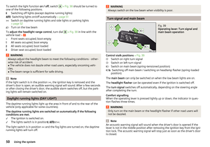 52
52 53
53 54
54 55
55 56
56 57
57 58
58 59
59 60
60 61
61 62
62 63
63 64
64 65
65 66
66 67
67 68
68 69
69 70
70 71
71 72
72 73
73 74
74 75
75 76
76 77
77 78
78 79
79 80
80 81
81 82
82 83
83 84
84 85
85 86
86 87
87 88
88 89
89 90
90 91
91 92
92 93
93 94
94 95
95 96
96 97
97 98
98 99
99 100
100 101
101 102
102 103
103 104
104 105
105 106
106 107
107 108
108 109
109 110
110 111
111 112
112 113
113 114
114 115
115 116
116 117
117 118
118 119
119 120
120 121
121 122
122 123
123 124
124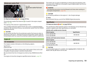 125
125 126
126 127
127 128
128 129
129 130
130 131
131 132
132 133
133 134
134 135
135 136
136 137
137 138
138 139
139 140
140 141
141 142
142 143
143 144
144 145
145 146
146 147
147 148
148 149
149 150
150 151
151 152
152 153
153 154
154 155
155 156
156 157
157 158
158 159
159 160
160 161
161 162
162 163
163 164
164 165
165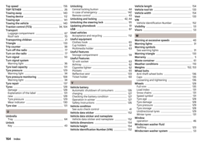 166
166 167
167 168
168 169
169 170
170 171
171