2016 NISSAN NOTE Freez
[x] Cancel search: FreezPage 311 of 3641
![NISSAN NOTE 2016 Service Repair Manual BCS-50
< ECU DIAGNOSIS INFORMATION >[WITH INTELLIGENT KEY SYSTEM]
BCM
DTC Index
INFOID:0000000012432335
NOTE:
The details of time display are as follows.
• CRNT: A malfunction is detected now.
• P](/manual-img/5/57363/w960_57363-310.png "NISSAN NOTE 2016 Service Repair Manual BCS-50
< ECU DIAGNOSIS INFORMATION >[WITH INTELLIGENT KEY SYSTEM]
BCM
DTC Index
INFOID:0000000012432335
NOTE:
The details of time display are as follows.
• CRNT: A malfunction is detected now.
• P")
BCS-50
< ECU DIAGNOSIS INFORMATION >[WITH INTELLIGENT KEY SYSTEM]
BCM
DTC Index
INFOID:0000000012432335
NOTE:
The details of time display are as follows.
• CRNT: A malfunction is detected now.
• PAST: A malfunction was detected in the past.
IGN counter is displayed on Freeze Frame Data.
5 • B2621: INSIDE ANTENNA 1
• B2622: INSIDE ANTENNA 2
• B2623: INSIDE ANTENNA 3
6 • B2626: OUTSIDE 1 ANTENNA
• B2627: OUTSIDE 2 ANTENNA
• B2628: OUTSIDE 3 ANTENNA
7 • C1704: LOW PRESSURE FL
• C1705: LOW PRESSURE FR
• C1706: LOW PRESSURE RR
• C1707: LOW PRESSURE RL
• C1708: [NO DATA] FL
• C1709: [NO DATA] FR
• C1710: [NO DATA] RR
• C1711: [NO DATA] RL
• C1716: [PRESS DATA ERR] FL
• C1717: [PRESS DATA ERR] FR
• C1718: [PRESS DATA ERR] RR
• C1719: [PRESS DATA ERR] RL
• C1729: VHCL SPEED SIG ERR
Priority DTC
CONSULT display Fail-safe
Freeze Frame Data
•Vehicle Speed
•Odo/Trip Meter
•Vehicle Condition Intelligent Key
warning lamp
ON Tire pressure monitor
warning lamp ON Reference page
No DTC is detected.
further testing
may be required. —— — — —
U1000: CAN COMM CIRCUIT — —— — BCS-63
U1010: CONTROL UNIT (CAN) — —— — BCS-64
U0415: VDC CAN CIR2 ×— ×— BCS-65
B2192: ID DISCORD BCM-ECM ×—— — SEC-54
B2193: CHAIN OF BCM-ECM×—— — SEC-55
B2195: ANTI SCANNING×—— — SEC-56
B2196: DONGLE NG×—— — SEC-57
B2198: NATS ANTENNA AMP×—— — SEC-59
B2555: STOP LAMP CIRCUIT —××—SEC-62
B2556: ENG START SW —×× —SEC-65
B2557: VEHICLE SPEED ×× × —SEC-67
B2562: LOW VOLTAGE —× —— BCS-66
B2601: SHIFT P SIGNAL×× × —SEC-68
B2602: SHIFT P DIAG ×× × —SEC-70
B2603: SHIFT POSITION ×× × —SEC-73
B2604: SHIFT PN DIAG CAN ×× × —SEC-77
B2605: SHIFT PN DIAG IPDM ×× × —SEC-80
B2608: STARTER RELAY ×× × —SEC-82
B260F: ECM CAN COMM ×× × —SEC-84
Revision: August 2015 2016 Versa Note
cardiagn.com
Page 312 of 3641
![NISSAN NOTE 2016 Service Repair Manual BCS
BCM
BCS-51
< ECU DIAGNOSIS INFORMATION > [WITH INTELLIGENT KEY SYSTEM]
C
D
E
F
G H
I
J
K L
B A
O P
N
B2614: ACC RELAY REQ FB —
××—PCS-56
B2615: IGN RELAY3 REQ FB — ××—PCS-58
B2616: IGN](/manual-img/5/57363/w960_57363-311.png "NISSAN NOTE 2016 Service Repair Manual BCS
BCM
BCS-51
< ECU DIAGNOSIS INFORMATION > [WITH INTELLIGENT KEY SYSTEM]
C
D
E
F
G H
I
J
K L
B A
O P
N
B2614: ACC RELAY REQ FB —
××—PCS-56
B2615: IGN RELAY3 REQ FB — ××—PCS-58
B2616: IGN")
BCS
BCM
BCS-51
< ECU DIAGNOSIS INFORMATION > [WITH INTELLIGENT KEY SYSTEM]
C
D
E
F
G H
I
J
K L
B A
O P
N
B2614: ACC RELAY REQ FB —
××—PCS-56
B2615: IGN RELAY3 REQ FB — ××—PCS-58
B2616: IGN RELAY2 REQ FB — ××—PCS-60
B2618: IGN RELAY1 REQ FB — ××—PCS-62
B261A: ENGINE SW —×× —PCS-63
B261F: ASCD CANCEL SW —×× —SEC-85
B2620: NEUTRAL SW —×× —SEC-88
B2621: INSIDE ANTENNA 1 —× —— DLK-65
B2622: INSIDE ANTENNA 2—× —— DLK-67
B2623: INSIDE ANTENNA 3—× —— DLK-69
B2626: OUTSIDE 1 ANTENNA — ×—— DLK-73
B2627: OUTSIDE 2 ANTENNA — ×—— DLK-71
B2628: OUTSIDE 3 ANTENNA — ×—— DLK-75
B26E8: CLUTCH SW×× × —SEC-91
B26F1: IGN RELAY OFF ×× × —PCS-65
B26F2: IGN RELAY ON ×× × —PCS-66
B26F3: START CONT RLY ON ×× × —SEC-94
B26F4: START CONT RLY OFF ×× × —SEC-95
B26F6: BCM —×× —PCS-68
B26F7: BCM ×× × —SEC-96
B26FB: CLUTCH SWITCH —×× —SEC-97
B26FC: KEY REGISTRATION — ××—SEC-98
C1704: LOW PRESSURE FL — —— ×
WT-25
C1705: LOW PRESSURE FR — —— ×
C1706: LOW PRESSURE RR — —— ×
C1707: LOW PRESSURE RL — —— ×
C1708: [NO DATA] FL —— — ×
WT-27
C1709: [NO DATA] FR —— — ×
C1710: [NO DATA] RR —— — ×
C1711: [NO DATA] RL —— — ×
C1716: [PRESS DATA ERR] FL — —— ×
WT-30
C1717: [PRESS DATA ERR] FR — —— ×
C1718: [PRESS DATA ERR] RR — —— ×
C1719: [PRESS DATA ERR] RL — —— ×
C1729: VHCL SPEED SIG ERR — —— ×WT-32
CONSULT display Fail-safe Freeze Frame Data
•Vehicle Speed
•Odo/Trip Meter
•Vehicle Condition Intelligent Key
warning lamp ON Tire pressure monitor
warning lamp ON Reference page
Revision: August 2015
2016 Versa Note
cardiagn.com
Page 500 of 3641
![NISSAN NOTE 2016 Service Repair Manual BRC-52
< BASIC INSPECTION >[VDC/TCS/ABS]
DIAGNOSIS AND REPAIR WORK FLOW
BASIC INSPECTION
DIAGNOSIS AND REPAIR WORK FLOW
Work FlowINFOID:0000000012430848
DETAILED FLOW
1.INTERVIEW THE CUSTOMER
Clarify](/manual-img/5/57363/w960_57363-499.png "NISSAN NOTE 2016 Service Repair Manual BRC-52
< BASIC INSPECTION >[VDC/TCS/ABS]
DIAGNOSIS AND REPAIR WORK FLOW
BASIC INSPECTION
DIAGNOSIS AND REPAIR WORK FLOW
Work FlowINFOID:0000000012430848
DETAILED FLOW
1.INTERVIEW THE CUSTOMER
Clarify")
BRC-52
< BASIC INSPECTION >[VDC/TCS/ABS]
DIAGNOSIS AND REPAIR WORK FLOW
BASIC INSPECTION
DIAGNOSIS AND REPAIR WORK FLOW
Work FlowINFOID:0000000012430848
DETAILED FLOW
1.INTERVIEW THE CUSTOMER
Clarify customer concerns before inspection. First of all, perform an interview utilizing BRC-53, "
Diagnostic
Work Sheet" and reproduce the symptom as well as fully understand it. Ask customer about his/her concerns
carefully. Check symptoms by driving vehicle with customer, if necessary.
CAUTION:
Customers are not professional. Never guess easily like “maybe the customer means that...,” or “ maybe the customer mentions this symptom”.
>> GO TO 2.
2.CHECK SYMPTOM
Reproduce the symptom that is indicated by the customer, based on the information from the customer
obtained in the interview. Also check that the sy mptom is not caused by fail-safe mode. Refer to BRC-39,
"Fail-safe".
CAUTION:
When the symptom is caused by normal operation, fully inspect each portion and obtain the under-
standing of customer that the sympt om is not caused by a malfunction.
>> GO TO 3.
3.PERFORM THE SELF-DIAGNOSIS
With CONSULT
1. Turn the ignition switch OFF → ON.
CAUTION:
Be sure to wait of 10 seconds after turning ignition switch OFF or ON.
2. Perform “Self Diagnostic Result” of “ABS”.
Is DTC detected?
YES >> Record or print Self Diagnostic Results and Freeze Frame Data (FFD). GO TO 4.
NO >> GO TO 6.
4.RECHECK THE SYMPTOM
With CONSULT
1. Erase “Self Diagnostic Result” of “ABS”.
2. Turn the ignition switch OFF → ON → OFF.
CAUTION:
Be sure to wait of 10 seconds after turning ignition switch OFF or ON.
3. Perform DTC confirmation procedures for the malfunctioning system. NOTE:
If some DTCs are detected at the some time, determine the order for performing the diagnosis based on
BRC-42, "
DTC Inspection Priority Chart".
Is DTC detected?
YES >> GO TO 5.
NO >> Check harness and connectors based on the information obtained in the interview. Refer to GI-42,
"Intermittent Incident".
5.REPAIR OR REPLACE MALFUNCTIONING COMPONENT
1. Repair or replace malfunctioning components.
2. Reconnect component or connector after repairing or replacing.
3. When DTC is detected, erase “Self Diagnostic Result” of “ABS”. CAUTION:
Revision: August 2015 2016 Versa Note
cardiagn.com
Page 669 of 3641
DEF-18
< BASIC INSPECTION >
DIAGNOSIS AND REPAIR WORK FLOW
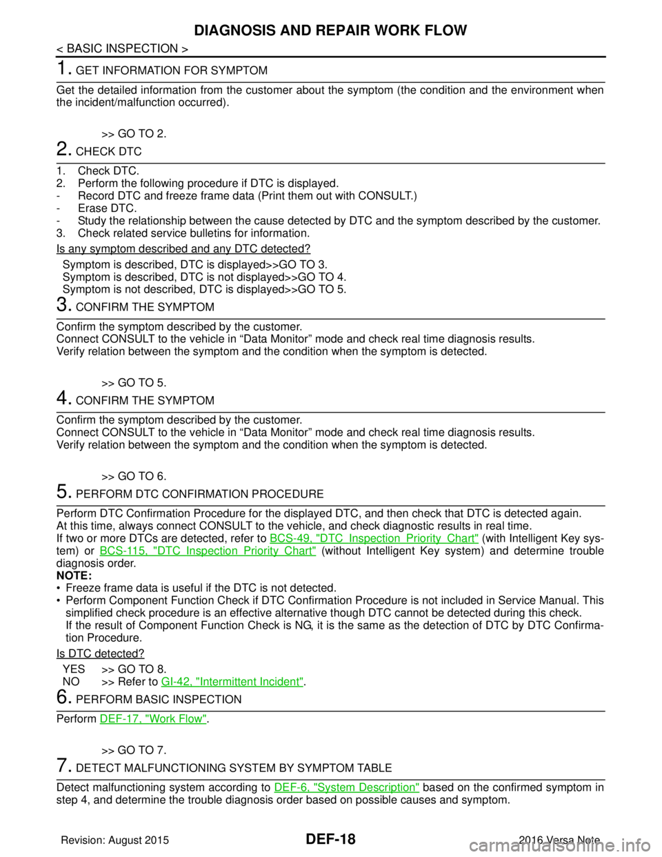
1. GET INFORMATION FOR SYMPTOM
Get the detailed information from the customer about the symptom (the condition and the environment when
the incident/malfunction occurred).
>> GO TO 2.
2. CHECK DTC
1. Check DTC.
2. Perform the following procedure if DTC is displayed.
- Record DTC and freeze frame data (P rint them out with CONSULT.)
- Erase DTC.
- Study the relationship between the cause detected by DTC and the symptom described by the customer.
3. Check related service bulletins for information.
Is any symptom described and any DTC detected?
Symptom is described, DTC is displayed>>GO TO 3.
Symptom is described, DTC is not displayed>>GO TO 4.
Symptom is not described, DTC is displayed>>GO TO 5.
3. CONFIRM THE SYMPTOM
Confirm the symptom described by the customer.
Connect CONSULT to the vehicle in “Data Monitor” mode and check real time diagnosis results.
Verify relation between the symptom and the condition when the symptom is detected.
>> GO TO 5.
4. CONFIRM THE SYMPTOM
Confirm the symptom described by the customer.
Connect CONSULT to the vehicle in “Data Monitor” mode and check real time diagnosis results.
Verify relation between the symptom and the condition when the symptom is detected.
>> GO TO 6.
5. PERFORM DTC CONFIRMATION PROCEDURE
Perform DTC Confirmation Procedure for the display ed DTC, and then check that DTC is detected again.
At this time, always connect CONSULT to the vehicle, and check diagnostic results in real time.
If two or more DTCs are detected, refer to BCS-49, "
DTCInspectionPriorityChart" (with Intelligent Key sys-
tem) or BCS-115, "
DTCInspectionPriorityChart" (without Intelligent Key system) and determine trouble
diagnosis order.
NOTE:
• Freeze frame data is useful if the DTC is not detected.
• Perform Component Function Check if DTC Confirmation Procedure is not included in Service Manual. This simplified check procedure is an effective alternat ive though DTC cannot be detected during this check.
If the result of Component Function Check is NG, it is the same as the detection of DTC by DTC Confirma-
tion Procedure.
Is DTC detected?
YES >> GO TO 8.
NO >> Refer to GI-42, "
Intermittent Incident".
6. PERFORM BASIC INSPECTION
Perform DEF-17, "
Work Flow".
>> GO TO 7.
7. DETECT MALFUNCTIONING SYSTEM BY SYMPTOM TABLE
Detect malfunctioning system according to DEF-6, "
System Description" based on the confirmed symptom in
step 4, and determine the trouble diagnosis order based on possible causes and symptom.
Revision: August 2015 2016 Versa Note
cardiagn.com
Page 751 of 3641
![NISSAN NOTE 2016 Service Repair Manual DLK-62
< BASIC INSPECTION >[WITH INTELLIGENT KEY SYSTEM]
DIAGNOSIS AND REPAIR WORK FLOW
1.GET INFORMATION FOR SYMPTOM
1. Get detailed information from the customer about the symptom (the condition and](/manual-img/5/57363/w960_57363-750.png "NISSAN NOTE 2016 Service Repair Manual DLK-62
< BASIC INSPECTION >[WITH INTELLIGENT KEY SYSTEM]
DIAGNOSIS AND REPAIR WORK FLOW
1.GET INFORMATION FOR SYMPTOM
1. Get detailed information from the customer about the symptom (the condition and")
DLK-62
< BASIC INSPECTION >[WITH INTELLIGENT KEY SYSTEM]
DIAGNOSIS AND REPAIR WORK FLOW
1.GET INFORMATION FOR SYMPTOM
1. Get detailed information from the customer about the symptom (the condition and the environment when the incident/malfunction occurs).
2. Check operation condition of the function that is malfunctioning.
>> GO TO 2.
2.CHECK DTC
1. Check DTC.
2. Perform the following procedure if DTC is detected.
- Record DTC and freeze frame data (P rint them out using CONSULT.)
- Erase DTC.
- Study the relationship between the cause detected by DTC and the symptom described by the customer.
3. Check related service bulletins for information.
Are any symptoms described and any DTC detected?
Symptom is described, DTC is detected>>GO TO 3.
Symptom is described, DTC is not detected>>GO TO 4.
Symptom is not described, DTC is detected>>GO TO 5.
3.CONFIRM THE SYMPTOM
Try to confirm the symptom described by the customer.
Also study the normal operation and fail-safe related to the symptom.
Verify relation between the symptom and the condition when the symptom is detected.
>> GO TO 5.
4.CONFIRM THE SYMPTOM
Try to confirm the symptom described by the customer.
Verify relation between the symptom and the condition when the symptom is detected.
>> GO TO 6.
5.PERFORM DTC CONFIRMATION PROCEDURE
Perform DTC CONFIRMATION PROCEDURE for the det ected DTC, and then check that DTC is detected
again. At this time, always connect CONSULT to the v ehicle, and check self diagnostic results in real time.
If two or more DTCs are detected, refer to BCS-49, "
DTCInspectionPriorityChart" and determine trouble
diagnosis order.
NOTE:
• Freeze frame data is useful if the DTC is not detected.
• Perform Component Function Check if DTC CONFIR MATION PROCEDURE is not included on Service
Manual. This simplified check procedure is an effect ive alternative though DTC cannot be detected during
this check.
If the result of Component Function Check is NG, it is the same as the detection of DTC by DTC CONFIR-
MATION PROCEDURE.
Is DTC detected?
YES >> GO TO 7.
NO >> Check according to GI-42, "
Intermittent Incident".
6.DETECT MALFUNCTIONING SYSTEM BY SYMPTOM DIAGNOSIS
Detect malfunctioning system according to SYMPTOM DIAGNOSIS based on the confirmed symptom in step
4, and determine the trouble diagnosis order based on possible causes and symptom.
Is the symptom described?
YES >> GO TO 7.
NO >> Monitor input data from related sensors or check voltage of related module terminals using CON- SULT.
7.DETECT MALFUNCTIONING PART BY DIAGNOSIS PROCEDURE
Revision: August 2015 2016 Versa Note
cardiagn.com
Page 915 of 3641
![NISSAN NOTE 2016 Service Repair Manual DLK-226
< BASIC INSPECTION >[WITHOUT INTELLIGENT KEY SYSTEM]
DIAGNOSIS AND REPAIR WORKFLOW
1.GET INFORMATION FOR SYMPTOM
Get the detailed information from the customer about the symptom (the condition](/manual-img/5/57363/w960_57363-914.png "NISSAN NOTE 2016 Service Repair Manual DLK-226
< BASIC INSPECTION >[WITHOUT INTELLIGENT KEY SYSTEM]
DIAGNOSIS AND REPAIR WORKFLOW
1.GET INFORMATION FOR SYMPTOM
Get the detailed information from the customer about the symptom (the condition")
DLK-226
< BASIC INSPECTION >[WITHOUT INTELLIGENT KEY SYSTEM]
DIAGNOSIS AND REPAIR WORKFLOW
1.GET INFORMATION FOR SYMPTOM
Get the detailed information from the customer about the symptom (the condition and the environment when
the incident/malfunction occurred).
>> GO TO 2.
2.CHECK DTC
1. Check DTC.
2. Perform the following procedure if DTC is displayed.
- Record DTC and freeze frame data (P rint them out with CONSULT.)
- Erase DTC.
- Study the relationship between the cause detected by DTC and the symptom described by the customer.
3. Check related service bulletins for information.
Is any symptom described and any DTC detected?
Symptom is described, DTC is displayed>>GO TO 3.
Symptom is described, DTC is not displayed>>GO TO 4.
Symptom is not described, DTC is displayed>>GO TO 5.
3.CONFIRM THE SYMPTOM
Confirm the symptom described by the customer.
Connect CONSULT to the vehicle in “Data Monitor” and check real time diagnosis results.
Verify relation between the symptom and the condition when the symptom is detected.
>> GO TO 5.
4.CONFIRM THE SYMPTOM
Confirm the symptom described by the customer.
Connect CONSULT to the vehicle in “Data Monitor” and check real time diagnosis results.
Verify relation between the symptom and the condition when the symptom is detected.
>> GO TO 6.
5.PERFORM DTC CONFIRMATION PROCEDURE
Perform DTC Confirmation Procedure for the display ed DTC, and then check that DTC is detected again.
At this time, always connect CONSULT to the vehicle, and check diagnostic results in real time.
If two or more DTCs are detected, refer to BCS-115, "
DTCInspectionPriorityChart" and determine trouble
diagnosis order.
NOTE:
• Freeze frame data is useful if the DTC is not detected.
• Perform Component Function Check if DTC Confirmation Procedure is not included in Service Manual. This
simplified check procedure is an effective alternat ive though DTC cannot be detected during this check.
If the result of Component Function Check is NG, it is the same as the detection of DTC by DTC Confirma-
tion Procedure.
Is DTC detected?
Ye s > > G O T O 7 .
No >> Refer to GI-42, "
Intermittent Incident".
6.DETECT MALFUNCTIONING SYSTEM BY SYMPTOM TABLE
Detect malfunctioning system according to SYMPTOM TABLE based on the confirmed symptom in step 4,
and determine the trouble diagnosis order based on possible causes and symptom.
>> GO TO 7.
7.DETECT MALFUNCTIONING PART BY DIAGNOSTIC PROCEDURE
Inspect according to Diagnostic Procedure of the system.
NOTE:
Revision: August 2015 2016 Versa Note
cardiagn.com
Page 1129 of 3641

EC-2
ELECTRIC IGNITION SYSTEM : System De-
scription ............................................................... ...
35
AIR CONDITIONING CUT CONTROL ................... ...36
AIR CONDITIONING CUT CONTROL : System
Diagram ..................................................................
37
AIR CONDITIONING CUT CONTROL : System
Description ..............................................................
37
CAN COMMUNICATION ........................................ ...38
CAN COMMUNICATION : System Description ......38
COOLING FAN CONTROL .................................... ...38
COOLING FAN CONTROL : System Diagram .......38
COOLING FAN CONTROL : System Description ...38
EVAPORATIVE EMISSION SYSTEM .................... ...40
EVAPORATIVE EMISSION SYSTEM : System
Diagram ............................................................... ...
40
EVAPORATIVE EMISSION SYSTEM : System
Description ........................................................... ...
40
INTAKE VALVE TIMING CONTROL ..................... ...41
INTAKE VALVE TIMING CONTROL : System Di-
agram .................................................................. ...
41
INTAKE VALVE TIMING CONTROL : System De-
scription ............................................................... ...
41
EXHAUST VALVE TIMING CONTROL ................. ...42
EXHAUST VALVE TIMING CONTROL : System
Diagram ............................................................... ...
42
EXHAUST VALVE TIMING CONTROL : System
Description ........................................................... ...
42
ENGINE PROTECTION CONTROL AT LOW EN-
GINE OIL PRESSURE ..............................................
43
ENGINE PROTECTION CONTROL AT LOW EN-
GINE OIL PRESSURE : S ystem Diagram ..............
43
ENGINE PROTECTION CONTROL AT LOW EN-
GINE OIL PRESSURE : S ystem Description .........
43
FUEL FILLER CAP WARNING SYSTEM .............. ...44
FUEL FILLER CAP WARNING SYSTEM :
System Diagram ....................................................
44
FUEL FILLER CAP WARNING SYSTEM : System
Description ........................................................... ...
44
AUTOMATIC SPEED CONTROL DEVICE (ASCD) ...45
AUTOMATIC SPEED CONTROL DEVICE (AS-
CD) : System Diagram ............................................
45
AUTOMATIC SPEED CONTROL DEVICE (AS-
CD) : System Description .......................................
45
OPERATION ......................................................47
AUTOMATIC SPEED CONTROL DEVICE (ASCD) ...47
AUTOMATIC SPEED CONTROL DEVICE (AS-
CD) : Switch Name and Function ...........................
47
ON BOARD DIAGNOSTIC (OBD) SYSTEM .....49
Diagnosis Description .......................................... ...49
GST (Generic Scan Tool) .......................................49
DIAGNOSIS SYSTEM (ECM) ............................50
DIAGNOSIS DESCRIPTION .................................. ...50
DIAGNOSIS DESCRIPTION : 1st Trip Detection
Logic and Two Trip Detection Logic ........................
50
DIAGNOSIS DESCRIPTION : DTC and Freeze
Frame Data .......................................................... ...
50
DIAGNOSIS DESCRIPTION : Counter System ......51
DIAGNOSIS DESCRIPTION : Driving Pattern ..... ...54
DIAGNOSIS DESCRIPTION : System Readiness
Test (SRT) Code .................................................. ...
55
DIAGNOSIS DESCRIPTION : Permanent Diag-
nostic Trouble Code (Permanent DTC) ..................
56
DIAGNOSIS DESCRIPTION : Malfunction Indica-
tor Lamp (MIL) ..................................................... ...
57
On Board Diagnosis Function .................................57
CONSULT Function ................................................60
ECU DIAGNOSIS INFORMATION .............71
ECM ...................................................................71
Reference Value .................................................. ...71
Fail Safe .................................................................83
DTC Inspection Priority Chart ...............................85
DTC Index ..............................................................87
Test Value and Test Limit .......................................90
WIRING DIAGRAM ....................................99
ENGINE CONTROL SYSTEM ........................ ...99
Wiring Diagram .................................................... ...99
BASIC INSPECTION .................................120
DIAGNOSIS AND REPAIR WORKFLOW ...... ..120
Work Flow ............................................................ .120
Diagnostic Work Sheet .........................................123
ADDITIONAL SERVICE WHEN REPLACING
ECM ..................................................................
125
Description ........................................................... .125
Work Procedure ....................................................125
VIN REGISTRATION ........................................127
Description ........................................................... .127
Work Procedure ....................................................127
ACCELERATOR PEDAL RELEASED POSI-
TION LEARNING ............................................ ..
128
Description ........................................................... .128
Work Procedure ....................................................128
THROTTLE VALVE CLOSED POSITION
LEARNING .......................................................
129
Description ........................................................... .129
Work Procedure ....................................................129
IDLE AIR VOLUME LEARNING .......................130
Description ........................................................... .130
Work Procedure ....................................................130
Revision: August 2015 2016 Versa Note
cardiagn.com
Page 1136 of 3641
![NISSAN NOTE 2016 Service Repair Manual PRECAUTIONSEC-9
< PRECAUTION > [HR16DE]
C
D
E
F
G H
I
J
K L
M A
EC
NP
O
General PrecautionsINFOID:0000000012431266
•
Always use a 12 volt battery as power source.
• Do not attempt to disconnect ba](/manual-img/5/57363/w960_57363-1135.png "NISSAN NOTE 2016 Service Repair Manual PRECAUTIONSEC-9
< PRECAUTION > [HR16DE]
C
D
E
F
G H
I
J
K L
M A
EC
NP
O
General PrecautionsINFOID:0000000012431266
•
Always use a 12 volt battery as power source.
• Do not attempt to disconnect ba")
PRECAUTIONSEC-9
< PRECAUTION > [HR16DE]
C
D
E
F
G H
I
J
K L
M A
EC
NP
O
General PrecautionsINFOID:0000000012431266
•
Always use a 12 volt battery as power source.
• Do not attempt to disconnect battery cables while engine is
running.
• Before connecting or disc onnecting the ECM harness con-
nector, turn ignition switch OFF and disconnect negative bat-
tery cable. Failure to do so may damage the ECM because
battery voltage is applied to ECM even if ignition switch is
turned OFF.
• Before removing parts, turn ig nition switch OFF and then dis-
connect battery ground cable.
• Do not disassemble ECM.
• If a battery cable is disconnected, the memory will return to
the ECM value.
The ECM will now start to self-c ontrol at its initial value. So,
engine operation can vary slight ly in this case. However, this
is not an indication of a malf unction. Do not replace parts
because of a slight variation.
• If the battery is disconnected, the following emission-related
diagnostic information will be lost within 24 hours.
- Diagnostic trouble codes
- 1st trip diagnostic trouble codes
- Freeze frame data
- 1st trip freeze frame data
- System readiness test (SRT) codes
- Test values
• When connecting or disconnecting pin connectors into or
from ECM, take care not to damage pin terminals (bend or
break).
Make sure that there are not any bends or breaks on ECM pin
terminal, when connecting pin connectors.
• Securely connect ECM harness connectors.
A poor connection can cause an extremely high (surge) volt-
age to develop in coil and cond enser, thus resulting in dam-
age to ICs.
• Keep engine control system harness at least 10 cm (4 in) away
from adjacent harness, to prevent engine control system mal-
functions due to receiving externa l noise, degraded operation
of ICs, etc.
• Keep engine control system parts and harness dry.
• Before replacing ECM, perform ECM Terminals and Reference
Value inspection and make sure ECM functions properly.
Refer to EC-71, "
Reference Value".
• Handle mass air flow sensor carefully to avoid damage.
• Do not clean mass air flow senso r with any type of detergent.
• Do not disassemble electric th rottle control actuator.
• Even a slight leak in the air intake system can cause serious
incidents.
• Do not shock or jar the camsh aft position sensor (PHASE),
crankshaft position sensor (POS).
SEF289H
PBIA9222J
PBIB0090E
MEF040D
Revision: August 2015 2016 Versa Note
cardiagn.com