2016 NISSAN NOTE Freez
[x] Cancel search: FreezPage 1247 of 3641
![NISSAN NOTE 2016 Service Repair Manual EC-120
< BASIC INSPECTION >[HR16DE]
DIAGNOSIS AND REPAIR WORKFLOW
BASIC INSPECTION
DIAGNOSIS AND REPAIR WORKFLOW
Work FlowINFOID:0000000012431348
OVERALL SEQUENCE
*1: Include 1st trip DTC.
*2: Include](/manual-img/5/57363/w960_57363-1246.png "NISSAN NOTE 2016 Service Repair Manual EC-120
< BASIC INSPECTION >[HR16DE]
DIAGNOSIS AND REPAIR WORKFLOW
BASIC INSPECTION
DIAGNOSIS AND REPAIR WORKFLOW
Work FlowINFOID:0000000012431348
OVERALL SEQUENCE
*1: Include 1st trip DTC.
*2: Include")
EC-120
< BASIC INSPECTION >[HR16DE]
DIAGNOSIS AND REPAIR WORKFLOW
BASIC INSPECTION
DIAGNOSIS AND REPAIR WORKFLOW
Work FlowINFOID:0000000012431348
OVERALL SEQUENCE
*1: Include 1st trip DTC.
*2: Include 1st trip freeze frame data.
JSBIA0123GB
Revision: August 2015
2016 Versa Note
cardiagn.com
Page 1248 of 3641
![NISSAN NOTE 2016 Service Repair Manual DIAGNOSIS AND REPAIR WORKFLOWEC-121
< BASIC INSPECTION > [HR16DE]
C
D
E
F
G H
I
J
K L
M A
EC
NP
O
DETAILED FLOW
1.GET INFORMATION FOR SYMPTOM
1. Get the detailed information from the customer about th](/manual-img/5/57363/w960_57363-1247.png "NISSAN NOTE 2016 Service Repair Manual DIAGNOSIS AND REPAIR WORKFLOWEC-121
< BASIC INSPECTION > [HR16DE]
C
D
E
F
G H
I
J
K L
M A
EC
NP
O
DETAILED FLOW
1.GET INFORMATION FOR SYMPTOM
1. Get the detailed information from the customer about th")
DIAGNOSIS AND REPAIR WORKFLOWEC-121
< BASIC INSPECTION > [HR16DE]
C
D
E
F
G H
I
J
K L
M A
EC
NP
O
DETAILED FLOW
1.GET INFORMATION FOR SYMPTOM
1. Get the detailed information from the customer about the symptom (the condition and the environment when the incident/malfunction occurred) using the “Diagnostic Work Sheet”. (Refer to EC-123, "
Diagnostic
Work Sheet".)
2. Ask if the customer requests I/M examination.
Malfunction information, obtained>>GO TO 2.
No malfunction information, but a request for I/M examination>>GO TO 13.
2.CHECK DTC
1. Check DTC.
2. Perform the following procedure if DTC is displayed.
- Record DTC and freeze frame data. (Pri nt them out with CONSULT or GST.)
- Erase DTC.
With CONSULT: “How to Erase DTC and 1st Trip DTC” in EC-60, "
CONSULT Function".
Without CONSULT: “How to Erase Self-diagnostic Results” in EC-57, "
On Board Diagnosis Function".
- Study the relationship between the cause detected by DTC and the symptom described by the customer.
(Symptom Table is useful. Refer to EC-464, "
Symptom Table".)
3. Check related service bulletins for information.
Is any symptom described and is any DTC detected?
Symptom is described, DTC is detected>>GO TO 3.
Symptom is described, DTC is not detected>>GO TO 4.
Symptom is not described, DTC is detected>>GO TO 5.
3.CONFIRM THE SYMPTOM
Try to confirm the symptom described by the customer (except MIL ON).
Also study the normal operation and fail sa fe related to the symptom. Refer to EC-470, "
Description" and EC-
83, "FailSafe".
Diagnostic Work Sheet is useful to verify the incident.
Verify relation between the symptom and t he condition when the symptom is detected.
>> GO TO 5.
4.CONFIRM THE SYMPTOM
Try to confirm the symptom described by the customer.
Also study the normal operation and fail sa fe related to the symptom. Refer to EC-470, "
Description" and EC-
83, "FailSafe".
Diagnostic Work Sheet is useful to verify the incident.
Verify relation between the symptom and t he condition when the symptom is detected.
>> GO TO 6.
5.PERFORM DTC CONFIRMATION PROCEDURE
Perform DTC CONFIRMATION PROCEDURE for the di splayed DTC, and then make sure that DTC is
detected again.
If two or more DTCs are detected, refer to EC-85, "
DTCInspectionPriorityChart" and determine trouble
diagnosis order.
NOTE:
• Freeze frame data is useful if the DTC is not detected.
• Perform Component Function Check if DTC CONF IRMATION PROCEDURE is not included on Service
Manual. This simplified check procedure is an effect ive alternative though DTC cannot be detected during
this check.
If the result of Component Function Check is NG, it is the same as the detection of DTC by DTC CONFIR-
MATION PROCEDURE.
Is DTC detected?
YES >> GO TO 10.
Revision: August 2015 2016 Versa Note
cardiagn.com
Page 1398 of 3641
![NISSAN NOTE 2016 Service Repair Manual P0300, P0301, P0302, P0303, P0304 MISFIRE
EC-271
< DTC/CIRCUIT DIAGNOSIS > [HR16DE]
C
D
E
F
G H
I
J
K L
M A
EC
NP
O
NO >> GO TO 3.
3.PERFORM DTC CONFIRMATION PROCEDURE-II
1. Turn ignition switch OFF a](/manual-img/5/57363/w960_57363-1397.png "NISSAN NOTE 2016 Service Repair Manual P0300, P0301, P0302, P0303, P0304 MISFIRE
EC-271
< DTC/CIRCUIT DIAGNOSIS > [HR16DE]
C
D
E
F
G H
I
J
K L
M A
EC
NP
O
NO >> GO TO 3.
3.PERFORM DTC CONFIRMATION PROCEDURE-II
1. Turn ignition switch OFF a")
P0300, P0301, P0302, P0303, P0304 MISFIRE
EC-271
< DTC/CIRCUIT DIAGNOSIS > [HR16DE]
C
D
E
F
G H
I
J
K L
M A
EC
NP
O
NO >> GO TO 3.
3.PERFORM DTC CONFIRMATION PROCEDURE-II
1. Turn ignition switch OFF and wait at least 10 seconds.
2. Start engine and drive the vehicle under the similar conditi ons to (1st trip) Freeze Frame Data for a certain
time. Refer to the table below.
Hold the accelerator pedal as steady as possible.
The similar conditions to (1st trip) Freeze Frame Da ta means the vehicle operation that the following con-
ditions should be satisfied at the same time.
CAUTION:
Always drive vehicle in safe manner according to traffic conditions and obey all traffic laws when
driving.
The time to driving varies according to the engine speed in the freeze frame data.
3. Check 1st trip DTC.
Is 1st trip DTC detected?
YES >> Go to EC-271, "Diagnosis Procedure".
NO >> INSPECTION END
Diagnosis ProcedureINFOID:0000000012431477
1.CHECK GROUND CONNECTION
Check the following.
• Connection condition of the ground F16 and F59
• Connection condition of the ground harness between engine assembly and vehicle body (if equipped)
Is the inspection result normal?
YES >> GO TO 2.
NO >> Repair or replace error-detected parts.
2.CHECK FOR INTAKE AIR LEAK AND PCV HOSE
1. Start engine and run it at idle speed.
2. Listen for the sound of the intake air leak.
3. Check PCV hose connection.
Is intake air leak detected?
YES >> Discover air leak location and repair.
NO >> GO TO 3.
3.CHECK FOR EXHAUST SYSTEM CLOGGING
Stop engine and visually check exhaust tube, three way catalyst and muffler for dents.
Is the inspection result normal?
YES-1 >> With CONSULT: GO TO 4.
YES-2 >> Without CONSULT: GO TO 5.
NO >> Repair or replace it.
Engine speed Engine speed in the freeze frame data ± 400 rpm
Vehicle speed Vehicle speed in the freeze frame data ± 10 km/h (6 MPH)
Engine coolant temperature (T) condition When the freeze frame data shows lower than 70°
C (158°F),
T should be lower than 70 °C (158 °F).
When the freeze frame data shows higher than or equal to 70 °C (158 °F),
T should be higher than or equal to 70° C (158°F).
Engine speed Time
Around 1,000 rpm Approximately 20 minutes
Around 2,000 rpm Approximately 10 minutes
More than 3,000 rpm Approximately 7 minutes
Revision: August 2015 2016 Versa Note
cardiagn.com
Page 1492 of 3641
![NISSAN NOTE 2016 Service Repair Manual P1212 TCS COMMUNICATION LINEEC-365
< DTC/CIRCUIT DIAGNOSIS > [HR16DE]
C
D
E
F
G H
I
J
K L
M A
EC
NP
O
P1212 TCS COMMUNICATION LINE
DescriptionINFOID:0000000012431567
This CAN communication line is use](/manual-img/5/57363/w960_57363-1491.png "NISSAN NOTE 2016 Service Repair Manual P1212 TCS COMMUNICATION LINEEC-365
< DTC/CIRCUIT DIAGNOSIS > [HR16DE]
C
D
E
F
G H
I
J
K L
M A
EC
NP
O
P1212 TCS COMMUNICATION LINE
DescriptionINFOID:0000000012431567
This CAN communication line is use")
P1212 TCS COMMUNICATION LINEEC-365
< DTC/CIRCUIT DIAGNOSIS > [HR16DE]
C
D
E
F
G H
I
J
K L
M A
EC
NP
O
P1212 TCS COMMUNICATION LINE
DescriptionINFOID:0000000012431567
This CAN communication line is used to control the
smooth engine operation during the TCS operation. Pulse
signals are exchanged between ECM and “ABS actuator and electric unit (control unit)”.
Be sure to erase the malf unction information such as DTC not onl y for “ABS actuator and electric unit
(control unit)” but also for ECM after TCS related repair.
DTC LogicINFOID:0000000012431568
DTC DETECTION LOGIC
NOTE:
• If DTC P1212 is displayed with DTC U1001, first pe rform the trouble diagnosis for DTC U1001. Refer
to EC-164, "
DTC Logic".
• If DTC P1212 is displayed with DT C P0607, first perform the trouble diagnosis for DTC P0607. Refer
to EC-353, "
DTC Logic".
Freeze frame data is not stored in the ECM for this self-diagnosis.
DTC CONFIRMATION PROCEDURE
1.PRECONDITIONING
If DTC Confirmation Procedure has been previously conducted, always perform the following procedure
before conducting the next test.
1. Turn ignition switch OFF and wait at least 10 seconds.
2. Turn ignition switch ON.
3. Turn ignition switch OFF and wait at least 10 seconds.
TESTING CONDITION:
Before performing the following procedure, confirm that battery voltage is more than 10.5V at idle.
>> GO TO 2.
2.PERFORM DTC CONFIRMATION PROCEDURE
1. Start engine and let it idle for at least 10 seconds.
2. Check 1st trip DTC.
Is 1st trip DTC detected?
YES >> Proceed to EC-365, "Diagnosis Procedure".
NO >> INSPECTION END
Diagnosis ProcedureINFOID:0000000012431569
Perform the trouble diagnosis for TCS. Refer to BRC-52, "Work Flow".
NOTE:
If DTC P1212 is displayed with DTC UXXXX and/or P0607, perform the following trouble diagnosis.
• Trouble diagnosis for DTC UXXXX Refer to EC-87, "
DTCIndex".
• Trouble diagnosis for DTC P0607 Refer to EC-353, "
DTC Logic".
DTC No.CONSULT screen terms
(Trouble diagnosis content) DTC detecting condition
Possible cause
P1212 TCS/CIRC
(TCS communication line) ECM can not receive the information from
“ABS actuator and electric unit (control
unit)” continuously. • Harness or connectors
(CAN communication line is open or shorted.)
• ABS actuator and electric unit (control unit)
• Dead (Weak) battery
Revision: August 2015 2016 Versa Note
cardiagn.com
Page 1493 of 3641
![NISSAN NOTE 2016 Service Repair Manual EC-366
< DTC/CIRCUIT DIAGNOSIS >[HR16DE]
P1217 ENGINE OVER TEMPERATURE
P1217 ENGINE OVER TEMPERATURE
DTC LogicINFOID:0000000012431570
DTC DETECTION LOGIC
NOTE:
•
If DTC P1217 is displayed with DTC](/manual-img/5/57363/w960_57363-1492.png "NISSAN NOTE 2016 Service Repair Manual EC-366
< DTC/CIRCUIT DIAGNOSIS >[HR16DE]
P1217 ENGINE OVER TEMPERATURE
P1217 ENGINE OVER TEMPERATURE
DTC LogicINFOID:0000000012431570
DTC DETECTION LOGIC
NOTE:
•
If DTC P1217 is displayed with DTC")
EC-366
< DTC/CIRCUIT DIAGNOSIS >[HR16DE]
P1217 ENGINE OVER TEMPERATURE
P1217 ENGINE OVER TEMPERATURE
DTC LogicINFOID:0000000012431570
DTC DETECTION LOGIC
NOTE:
•
If DTC P1217 is displayed with DTC UXXXX, first perform the trouble diagnosis for DTC UXXXX.
• If DTC P1217 is displayed with DTC P0607, first perform the trouble diagno sis for DTC P0607. Refer
to EC-353, "
DTC Logic".
If the cooling fan or another component in the cooling system malfunctions, engine coolant temperature will
rise.
When the engine coolant temperature reaches an abnorma lly high temperature condition, a malfunction is
indicated.
CAUTION:
When a malfunction is indicated, be sure to replace the coolant. Refer to CO-9, "
Refilling". Also,
replace the engine oil. Refer to LU-8, "
Refilling".
1. Fill radiator with coolant up to specified level with a filling speed of 2 liters per minute. Be sure to use coolant with the proper mixture ratio. Refer to MA-12, "
Anti-Freeze Coolant Mixture Ratio".
2. After refilling coolant, run engine to en sure that no water-flow noise is emitted.
DTC CONFIRMATION PROCEDURE
1.PERFORM COMPONENT FUNCTION CHECK
Perform component function check. Refer to EC-366, "
Component Function Check".
NOTE:
Use component function check to check the overall function of the cooling fan. During this check, a DTC might
not be confirmed.
Is the inspection result normal?
YES >> INSPECTION END
NO >> Go to EC-367, "
Diagnosis Procedure".
Component Function CheckINFOID:0000000012431571
1.PERFORM COMPONENT FUNCTION CHECK-I
WARNING:
Never remove the radiator cap when the engine is hot. Serious burns could be caused by high pres-
sure fluid escaping from the radiator.
Wrap a thick cloth around cap. Carefully remove the cap by turning it a quarter turn to allow built-up
pressure to escape. Then turn the cap all the way off.
DTC No. Trouble diagnosis content DTC detecting conditionPossible cause
P1217 Engine over temperature
(Overheat) • Cooling fan does not operate properly
(Overheat).
• Cooling fan system does not operate properly (Overheat).
• Engine coolant was not added to the
system using the proper filling method.
• Engine coolant is not within the specified range. • Harness or connectors
(The cooling fan circuit is open or shorted.)
• IPDM E/R (Cooling fan low relay, high relay)
• Cooling fan relay
• Cooling fan motor
•Radiator hose
•Radiator
•Radiator cap
• Reservoir tank
• Water pump
•Thermostat
Revision: August 2015 2016 Versa Note
cardiagn.com
Page 1510 of 3641
![NISSAN NOTE 2016 Service Repair Manual P1572 ASCD BRAKE SWITCHEC-383
< DTC/CIRCUIT DIAGNOSIS > [HR16DE]
C
D
E
F
G H
I
J
K L
M A
EC
NP
O
P1572 ASCD BRAKE SWITCH
DTC LogicINFOID:0000000012431593
DTC DETECTION LOGIC
NOTE:
•
If DTC P1572 is](/manual-img/5/57363/w960_57363-1509.png "NISSAN NOTE 2016 Service Repair Manual P1572 ASCD BRAKE SWITCHEC-383
< DTC/CIRCUIT DIAGNOSIS > [HR16DE]
C
D
E
F
G H
I
J
K L
M A
EC
NP
O
P1572 ASCD BRAKE SWITCH
DTC LogicINFOID:0000000012431593
DTC DETECTION LOGIC
NOTE:
•
If DTC P1572 is")
P1572 ASCD BRAKE SWITCHEC-383
< DTC/CIRCUIT DIAGNOSIS > [HR16DE]
C
D
E
F
G H
I
J
K L
M A
EC
NP
O
P1572 ASCD BRAKE SWITCH
DTC LogicINFOID:0000000012431593
DTC DETECTION LOGIC
NOTE:
•
If DTC P1572 is displayed with DT C P0605, first perform the trouble diagnosis for DTC P0605. Refer
to EC-351, "
DTC Logic".
• This self-diagnosis has the one trip detection logic. When malfunction A is detected, DTC is not
stored in ECM memory. And in that case, 1st trip DTC and 1st trip freeze frame data are displayed.
1st trip DTC is erased when ignition switch OFF. And even when ma lfunction A is detected in two
consecutive trips, DTC is not stored in ECM memory.
DTC CONFIRMATION PROCEDURE
1.PRECONDITIONING
If DTC Confirmation Procedure has been previously conducted, always perform the following procedure
before conducting the next test.
1. Turn ignition switch OFF and wait at least 10 seconds.
2. Turn ignition switch ON.
3. Turn ignition switch OFF and wait at least 10 seconds.
NOTE:
Procedure for malfunction B is not described here. It take s extremely long time to complete procedure for mal-
function B. By performing procedure for malfunction A, the incident that causes malfunction B can be
detected.
>> GO TO 2.
2.PERFORM DTC CONFIRMATION PROCEDURE FOR MALFUNCTION A
1. Start engine.
2. Press MAIN switch and make sure that CRUISE indicator is displayed in combination meter.
3. Drive the vehicle for at least 5 consecut ive seconds as per the following conditions.
CAUTION:
Always drive vehicle at a safe speed.
NOTE:
This procedure may be conducted with the drive wheel s lifted in the shop or by driving the vehicle.
If a road test is expected to be easier , it is unnecessary to lift the vehicle.
4. Check DTC.
Is DTC detected?
YES >> Proceed to EC-388, "Diagnosis Procedure".
NO >> GO TO 3.
3.PERFORM DTC CONFIRMATION PROCEDURE FOR MALFUNCTION B
1. Drive the vehicle for at least 5 consecut ive seconds as per the following conditions.
CAUTION:
DTC No. CONSULT screen terms
(Trouble diagnosis content) DTC detecting condition
Possible cause
P1572 ASCD BRAKE SW
(ASCD brake switch) A)
When the vehicle speed is above 30 km/h
(19 MPH), ON signals from the stop lamp
switch and the ASCD brake switch are
sent to the ECM at the same time. • Harness or connectors
(Stop lamp switch circuit is shorted.)
(ASCD brake switch circuit is shorted.)
• Stop lamp switch
• ASCD brake switch
• Incorrect stop lamp switch installation
• Incorrect ASCD brake switch installation
•ECM
B)
ASCD brake switch signal is not sent to
ECM for extremely long time while the ve-
hicle is driving.
Vehicle speed More than 30 km/h (19 mph)
Selector lever Suitable position
Revision: August 2015
2016 Versa Note
cardiagn.com
Page 1930 of 3641
GI-42
< BASIC INSPECTION >
SERVICE INFORMATION FOR ELECTRICAL INCIDENT
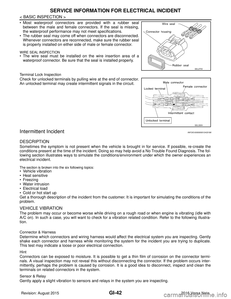
• Most waterproof connectors are provided with a rubber sealbetween the male and female connectors. If the seal is missing,
the waterproof performance may not meet specifications.
• The rubber seal may come off when connectors are disconnected. Whenever connectors are reconnected, make sure the rubber seal
is properly installed on either side of male or female connector.
WIRE SEAL INSPECTION
• The wire seal must be installed on the wire insertion area of awaterproof connector. Be sure that the seal is installed properly.
Terminal Lock Inspection
Check for unlocked terminals by pulling wire at the end of connector.
An unlocked terminal may create intermittent signals in the circuit.
Intermittent IncidentINFOID:0000000012433186
DESCRIPTION
Sometimes the symptom is not present when the vehicle is brought in for service. If possible, re-create the
conditions present at the time of the incident. Doi ng so may help avoid a No Trouble Found Diagnosis. The fol-
lowing section illustrates ways to simulate the condi tions/environment under which the owner experiences an
electrical incident.
The section is broken into the six following topics:
• Vehicle vibration
• Heat sensitive
• Freezing
• Water intrusion
• Electrical load
• Cold or hot start up
Get a thorough description of the incident from the customer. It is important for simulating the conditions of the
problem.
VEHICLE VIBRATION
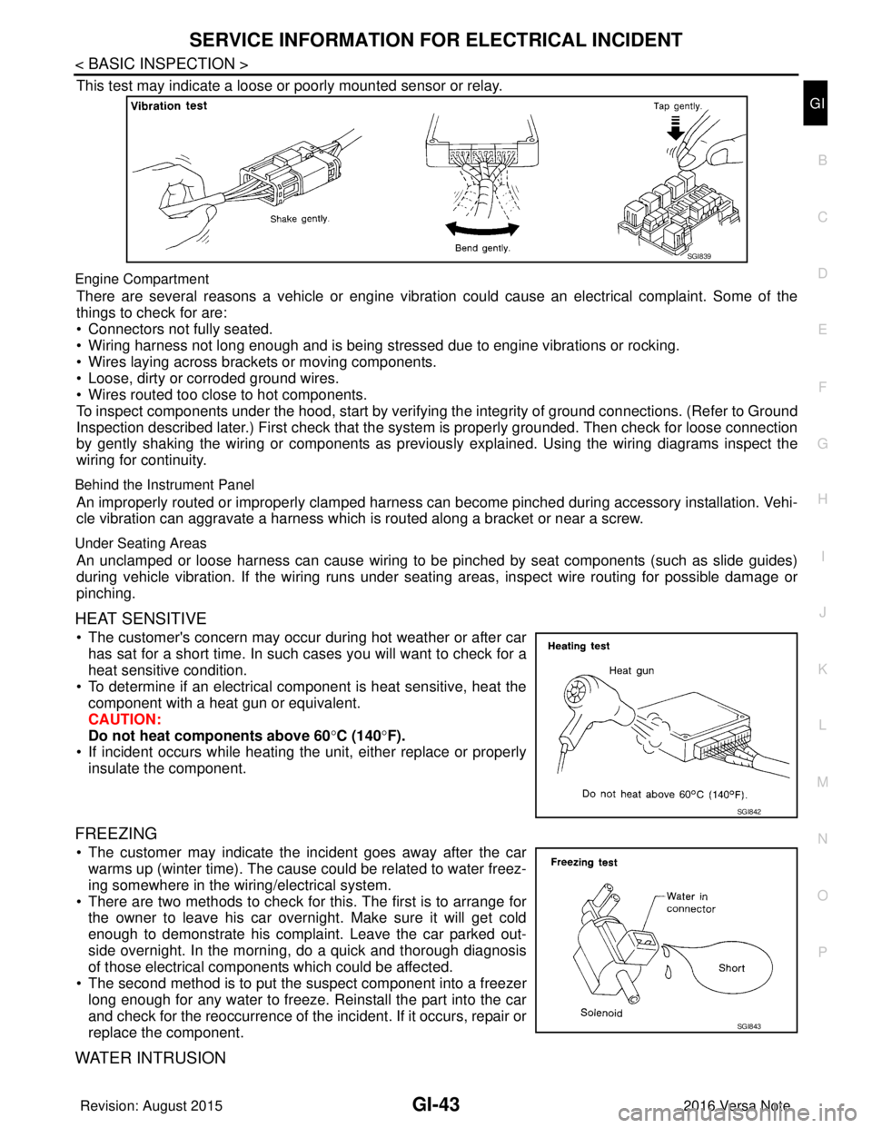
The problem may occur or become worse while driving on a rough road or when engine is vibrating (idle with
A/C on). In such a case, you will want to check for a vi bration related condition. Refer to the following illustra-
tion.
Connector & Harness
Determine which connectors and wiring harness would affect the electrical system you are inspecting. Gently
shake each connector and harness while monitoring the sy stem for the incident you are trying to duplicate.
This test may indicate a loose or poor electrical connection.
Hint
Connectors can be exposed to moisture. It is possible to get a thin film of corrosion on the connector termi-
nals. A visual inspection may not reveal this without disconnecting the connector. If the problem occurs inter-
mittently, perhaps the problem is caused by corrosion. It is a good idea to disconnect, inspect and clean the
terminals on related connectors in the system.
Sensor & Relay
Gently apply a slight vibration to sensors and relays in the system you are inspecting.
SEL275V
SEL330V
Revision: August 2015 2016 Versa Note
cardiagn.com
Page 1931 of 3641
SERVICE INFORMATION FOR ELECTRICAL INCIDENTGI-43
< BASIC INSPECTION >
C
DE
F
G H
I
J
K L
M B
GI
N
O P
This test may indicate a loose or poorly mounted sensor or relay.
Engine Compartment
There are several reasons a vehicle or engine vibration could cause an electrical complaint. Some of the
things to check for are:
• Connectors not fully seated.
• Wiring harness not long enough and is being stressed due to engine vibrations or rocking.
• Wires laying across brackets or moving components.
• Loose, dirty or corroded ground wires.
• Wires routed too close to hot components.
To inspect components under the hood, start by verifyi ng the integrity of ground connections. (Refer to Ground
Inspection described later.) First check that the system is properly grounded. Then check for loose connection
by gently shaking the wiring or components as previous ly explained. Using the wiring diagrams inspect the
wiring for continuity.
Behind the Instrument Panel
An improperly routed or improperly clamped harness can become pinched during accessory installation. Vehi-
cle vibration can aggravate a harness which is routed along a bracket or near a screw.
Under Seating Areas
An unclamped or loose harness can cause wiring to be pinched by seat components (such as slide guides)
during vehicle vibration. If the wiring runs under s eating areas, inspect wire routing for possible damage or
pinching.
HEAT SENSITIVE
• The customer's concern may occur during hot weather or after car has sat for a short time. In such cases you will want to check for a
heat sensitive condition.
• To determine if an electrical component is heat sensitive, heat the component with a heat gun or equivalent.
CAUTION:
Do not heat components above 60 °C (140° F).
• If incident occurs while heating t he unit, either replace or properly
insulate the component.
FREEZING
• The customer may indicate the incident goes away after the car warms up (winter time). The cause could be related to water freez-
ing somewhere in the wiring/electrical system.
• There are two methods to check for this. The first is to arrange for the owner to leave his car overnight. Make sure it will get cold
enough to demonstrate his complaint. Leave the car parked out-
side overnight. In the morning, do a quick and thorough diagnosis
of those electrical components which could be affected.
• The second method is to put the suspect component into a freezer long enough for any water to freeze. Reinstall the part into the car
and check for the reoccurrence of the incident. If it occurs, repair or
replace the component.
WATER INTRUSION
SGI839
SGI842
SGI843
Revision: August 2015 2016 Versa Note
cardiagn.com