2016 NISSAN NOTE engine
[x] Cancel search: enginePage 2746 of 3641
PRECAUTIONSWT-3
< PRECAUTION >
C
DF
G H
I
J
K L
M A
B
WT
N
O P
PRECAUTION
PRECAUTIONS
Precaution for Supplemental Restraint System (SRS) "AIR BAG" and "SEAT BELT
PRE-TENSIONER"
INFOID:0000000012432421
The Supplemental Restraint System such as “AIR BAG” and “SEAT BELT PRE-TENSIONER”, used along
with a front seat belt, helps to reduce the risk or severi ty of injury to the driver and front passenger for certain
types of collision. Information necessary to service the system safely is included in the SR and SB section of
this Service Manual.
WARNING:
• To avoid rendering the SRS inoper ative, which could increase the risk of personal injury or death in
the event of a collision which would result in air bag inflation, all maintenance must be performed by
an authorized NISSAN/INFINITI dealer.
• Improper maintenance, including in correct removal and installation of the SRS, can lead to personal
injury caused by unintentional act ivation of the system. For removal of Spiral Cable and Air Bag
Module, see the SR section.
• Do not use electrical test equipm ent on any circuit related to the SRS unless instructed to in this
Service Manual. SRS wiring harnesses can be identi fied by yellow and/or orange harnesses or har-
ness connectors.
PRECAUTIONS WHEN USING POWER TOOLS (AIR OR ELECTRIC) AND HAMMERS
WARNING:
• When working near the Airbag Diagnosis Sensor Un it or other Airbag System sensors with the Igni-
tion ON or engine running, DO NOT use air or el ectric power tools or strike near the sensor(s) with a
hammer. Heavy vibration could activate the sensor( s) and deploy the air bag(s), possibly causing
serious injury.
• When using air or electric power tools or hammers, always switch the Ignition OFF, disconnect the
battery and wait at least three mi nutes before performing any service.
Service Notice and Precautions for TPMSINFOID:0000000012432422
WARNING:
Radio waves could adversely affect electric medical equipment. Those who use a pacemaker should
contact the electric medical equipment manufacturer for the possible influences before use.
• Low tire pressure warning lamp blinks for 1 minute, then turns ON when occurring any malfunction except low tire pressure. Erase the self-diagnosis memories fo r Tire Pressure Monitoring System (TPMS), or regis-
ter the ID to turn low tire pressure warning lamp OFF. For ID registration, refer to WT-22, "
Work Procedure".
• ID registration is required when replacing or rotating wheels, replacing tire pressure sensor or BCM. Refer to WT-22, "
Work Procedure".
• Replace grommet seal, valve core and valve cap of tire pressure sensor in TPMS, when replacing each tire by reaching the wear limit. Refer to WT-49, "
Removal and Installation".
• Because the tire pressure sensor conforms to North America radio law, the following items must be
observed.
- The sensor may be used only in North America.
- It may not be used in any method other than the specified method.
- It must not be disassembled or modified.
Service Notice and Pr ecautions for Road WheelINFOID:0000000012432423
• Genuine NISSAN aluminum wheel is designed for each type of vehicle. Use it on the specified vehicle only.
• Use Genuine NISSAN parts for the road wheels, valve caps and wheel nuts.
• Always use them after adjusting the wheel balance. For the balance weights, use Genuine NISSAN alumi-
num wheel weights.
• Use caution when handling the aluminum wheels, because they can be easily scratched. When removing
dirt, do not use any abrasives, a wire brush, or other items that may scratch the coating. Use a neutral deter-
gent if a detergent is needed.
• After driving on roads scattered with anti-icing salts, wash off the wheels completely.
• When installing road wheels onto the vehicle, always wipe off any dirt or foreign substances to prevent them
from being trapped between the contact surfaces of wheel.
Revision: August 2015 2016 Versa Note
cardiagn.com
Page 2751 of 3641
WT-8
< SYSTEM DESCRIPTION >
SYSTEM
SYSTEM
TIRE PRESSURE MONITORING SYSTEM
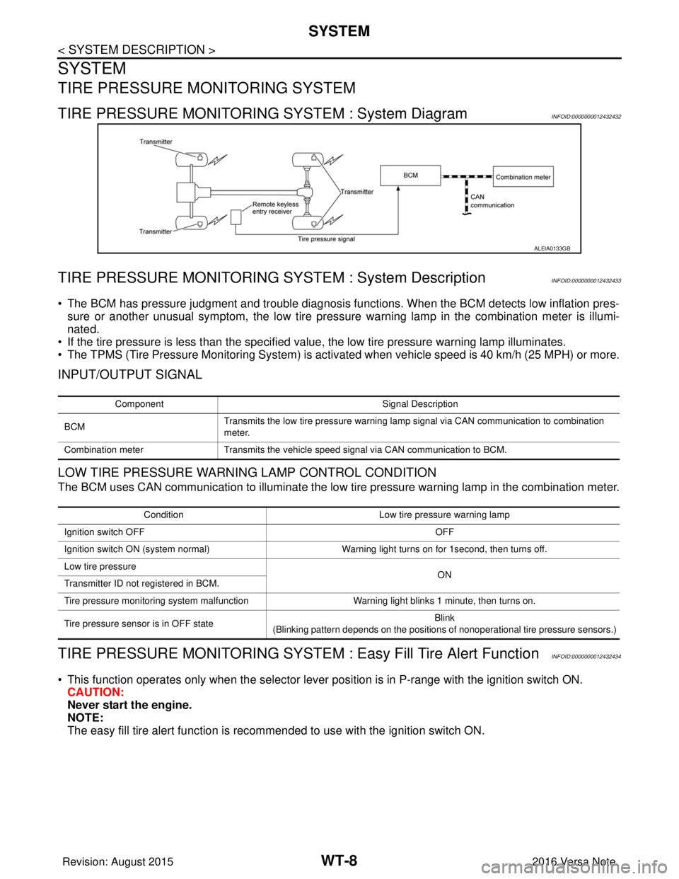
TIRE PRESSURE MONITORING SYSTEM : System DiagramINFOID:0000000012432432
TIRE PRESSURE MONITORING SY STEM : System DescriptionINFOID:0000000012432433
• The BCM has pressure judgment and trouble diagnosis functions. When the BCM detects low inflation pres-
sure or another unusual symptom, the low tire pressure warning lamp in the combination meter is illumi-
nated.
• If the tire pressure is less than the specified value, the low tire pressure warning lamp illuminates.
• The TPMS (Tire Pressure Monitoring System) is activated when vehicle s peed is 40 km/h (25 MPH) or more.
INPUT/OUTPUT SIGNAL
LOW TIRE PRESSURE WARNING LAMP CONTROL CONDITION
The BCM uses CAN communication to illuminate the low tire pressure warning lamp in the combination meter.
TIRE PRESSURE MONITORING SYSTEM : Easy Fill Tire Alert FunctionINFOID:0000000012432434
• This function operates only when the selector lever position is in P-range with the ignition switch ON.
CAUTION:
Never start the engine.
NOTE:
The easy fill tire alert function is reco mmended to use with the ignition switch ON.
ALEIA0133GB
Component Signal Description
BCM Transmits the low tire pressure warning lamp signal via CAN communication to combination
meter.
Combination meter Transmits the vehicle speed signal via CAN communication to BCM.
Condition Low tire pressure warning lamp
Ignition switch OFF OFF
Ignition switch ON (system normal) Warning light turns on for 1second, then turns off.
Low tire pressure ON
Transmitter ID not registered in BCM.
Tire pressure monitoring system malfunction Warning light blinks 1 minute, then turns on.
Tire pressure sensor is in OFF state Blink
(Blinking pattern depends on the positions of nonoperational tire pressure sensors.)
Revision: August 2015 2016 Versa Note
cardiagn.com
Page 2799 of 3641
SB-2
< PRECAUTION >
PRECAUTIONS
PRECAUTION
PRECAUTIONS
Precaution for Supplemental Restraint System (SRS) "AIR BAG" and "SEAT BELT
PRE-TENSIONER"
INFOID:0000000012430695
The Supplemental Restraint System such as “A IR BAG” and “SEAT BELT PRE-TENSIONER”, used along
with a front seat belt, helps to reduce the risk or severity of injury to the driver and front passenger for certain
types of collision. Information necessary to service the system safely is included in the SR and SB section of
this Service Manual.
WARNING:
• To avoid rendering the SRS inopera tive, which could increase the risk of personal injury or death in
the event of a collision which would result in air bag inflation, all maintenance must be performed by
an authorized NISSAN/INFINITI dealer.
• Improper maintenance, including in correct removal and installation of the SRS, can lead to personal
injury caused by unintent ional activation of the system. For re moval of Spiral Cable and Air Bag
Module, see the SR section.
• Do not use electrical test equipmen t on any circuit related to the SRS unless instructed to in this
Service Manual. SRS wiring harn esses can be identified by yellow and/or orange harnesses or har-
ness connectors.
PRECAUTIONS WHEN USING POWER TOOLS (AIR OR ELECTRIC) AND HAMMERS
WARNING:
• When working near the Airbag Diagnosis Sensor Unit or other Airbag System sensors with the Igni-
tion ON or engine running, DO NOT use air or electri c power tools or strike near the sensor(s) with a
hammer. Heavy vibration could activate the sensor( s) and deploy the air bag(s), possibly causing
serious injury.
• When using air or electric power tools or hammers , always switch the Ignition OFF, disconnect the
battery and wait at least three minutes before performing any service.
Precaution for Seat Belt ServiceINFOID:0000000012430696
CAUTION:
• Before removing the seat belt pre-tensioner assembl y, turn the ignition switch OFF, disconnect both
battery terminals and wait at least three minutes. For approximately three minutes after the battery
terminals have been removed, it is still possible for the air bag and seat belt pre-tensioner to deploy.
Therefore, do not attempt work on any SRS connectors or wires until at least three minutes have
passed.
• After replacing or reinstalling seat belt pre -tensioner assembly or reconnecting seat belt pre-ten-
sioner assembly connector, make sure entire SRS operates properly. Refer to SRC-14, "
Description".
• Do not disassemble buckle or seat belt assembly.
• Replace anchor bolts if th ey are deformed or worn out.
• Do not oil tongue or buckle.
• If any component of seat belt assembly is questionable, do not re pair. Replace the whole seat belt
assembly.
• If webbing is cut, frayed or damaged, replace seat belt assembly.
• When replacing seat belt assembly, use a genuine NISSAN seat belt assembly.
Precaution for WorkINFOID:0000000012430697
• When removing or disassembling each component, be careful not to damage or deform it. If a component may be subject to interference, be sure to protect it with a shop cloth.
• When removing (disengaging) components with a screwdriver or similar tool, be sure to wrap the component with a shop cloth or vinyl tape to protect it.
• Protect the removed parts with a shop cloth and prevent them from being dropped.
• Replace a deformed or damaged clip.
• If a part is specified as a non-reusable part, always replace it with a new one.
• Be sure to tighten bolts and nuts securely to the specified torque.
• After installation is complete, be sure to check that each part works properly.
• Follow the steps below to clean components:
Revision: August 2015 2016 Versa Note
cardiagn.com
Page 2815 of 3641

SE-2
< PRECAUTION >
PRECAUTIONS
PRECAUTION
PRECAUTIONS
Precaution for Supplemental Restraint System (SRS) "AIR BAG" and "SEAT BELT
PRE-TENSIONER"
INFOID:0000000012432026
The Supplemental Restraint System such as “A IR BAG” and “SEAT BELT PRE-TENSIONER”, used along
with a front seat belt, helps to reduce the risk or severity of injury to the driver and front passenger for certain
types of collision. Information necessary to service the system safely is included in the SR and SB section of
this Service Manual.
WARNING:
• To avoid rendering the SRS inopera tive, which could increase the risk of personal injury or death in
the event of a collision which would result in air bag inflation, all maintenance must be performed by
an authorized NISSAN/INFINITI dealer.
• Improper maintenance, including in correct removal and installation of the SRS, can lead to personal
injury caused by unintent ional activation of the system. For re moval of Spiral Cable and Air Bag
Module, see the SR section.
• Do not use electrical test equipmen t on any circuit related to the SRS unless instructed to in this
Service Manual. SRS wiring harn esses can be identified by yellow and/or orange harnesses or har-
ness connectors.
PRECAUTIONS WHEN USING POWER TOOLS (AIR OR ELECTRIC) AND HAMMERS
WARNING:
• When working near the Airbag Diagnosis Sensor Unit or other Airbag System sensors with the Igni-
tion ON or engine running, DO NOT use air or electri c power tools or strike near the sensor(s) with a
hammer. Heavy vibration could activate the sensor( s) and deploy the air bag(s), possibly causing
serious injury.
• When using air or electric power tools or hammers , always switch the Ignition OFF, disconnect the
battery and wait at least three minutes before performing any service.
Precaution for WorkINFOID:0000000012432027
• When removing or disassembling each component, be careful not to damage or deform it. If a component may be subject to interference, be sure to protect it with a shop cloth.
• When removing (disengaging) components with a screwdriver or similar tool, be sure to wrap the component with a shop cloth or vinyl tape to protect it.
• Protect the removed parts with a shop cloth and prevent them from being dropped.
• Replace a deformed or damaged clip.
• If a part is specified as a non-reusable part, always replace it with a new one.
• Be sure to tighten bolts and nuts securely to the specified torque.
• After installation is complete, be sure to check that each part works properly.
• Follow the steps below to clean components:
- Water soluble dirt:
• Dip a soft cloth into lukewarm water, wring the water out of the cloth and wipe the dirty area.
• Then rub with a soft, dry cloth.
- Oily dirt:
• Dip a soft cloth into lukewarm water with mild detergent (concentration: within 2 to 3%) and wipe the dirty area.
• Then dip a cloth into fresh water, wring the water out of the cloth and wipe the detergent off.
• Then rub with a soft, dry cloth.
- Do not use organic solvent such as thinner, benzene, alcohol or gasoline.
- For genuine leather seats, use a genuine leather seat cleaner.
Revision: August 2015 2016 Versa Note
cardiagn.com
Page 2816 of 3641
PREPARATIONSE-3
< PREPARATION >
C
DE
F
G H
I
K L
M A
B
SE
N
O P
PREPARATION
PREPARATION
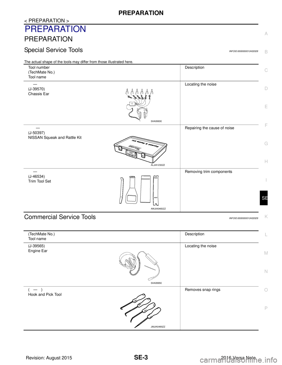
Special Service ToolsINFOID:0000000012432028
The actual shape of the tools may di ffer from those illustrated here.
Commercial Service ToolsINFOID:0000000012432029
Tool number
(TechMate No.)
Tool name Description
—
(J-39570)
Chassis Ear Locating the noise
—
(J-50397)
NISSAN Squeak and Rattle Kit Repairing the cause of noise
—
(J-46534)
Trim Tool Set Removing trim components
SIIA0993E
ALJIA1232ZZ
AWJIA0483ZZ
(TechMate No.)
Tool name
Description
(J-39565)
Engine Ear Locating the noise
(—)
Hook and Pick Tool Removes snap rings
SIIA0995E
JMJIA0490ZZ
Revision: August 2015
2016 Versa Note
cardiagn.com
Page 2822 of 3641
SQUEAK AND RATTLE TROUBLE DIAGNOSESSE-9
< SYMPTOM DIAGNOSIS >
C
DE
F
G H
I
K L
M A
B
SE
N
O P
If possible, drive the vehicle with the customer until the noise is duplicated. Note any additional information on
the Diagnostic Worksheet regarding the conditions or lo cation of the noise. This information can be used to
duplicate the same conditions when you confirm the repair.
If the noise can be duplicated easily during the test drive, to help identify the source of the noise, try to dupli-
cate the noise with the vehicle stopped by doing one or all of the following:
1) Close a door.
2) Tap or push/pull around the area where the noise appears to be coming from.
3) Rev the engine.
4) Use a floor jack to recreate vehicle “twist”.
5) At idle, apply engine load (electrical load, half-clutch on M/T model, drive position on CVT and A/T models).
6) Raise the vehicle on a hoist and hit a tire with a rubber hammer.
• Drive the vehicle and attempt to duplicate the conditions the customer states exist when the noise occurs.
• If it is difficult to duplicate the noise, drive the vehicle slowly on an undulating or rough road to stress the
vehicle body.
CHECK RELATED SERVICE BULLETINS
After verifying the customer concern or symptom, check ASIST for Technical Service Bulletins (TSBs) related
to that concern or symptom.
If a TSB relates to the symptom, follow the procedure to repair the noise.
LOCATE THE NOISE AND IDENTIFY THE ROOT CAUSE
1. Narrow down the noise to a general area. To help pinpoint the source of the noise, use a listening tool (Chassis Ear: J-39570, Engine Ear: J-39565 and mechanic's stethoscope).
2. Narrow down the noise to a more specific area and identify the cause of the noise by: • removing the components in the area that you suspect the noise is coming from.Do not use too much force when removing clips and fasteners, otherwise clips and fasteners can be
broken or lost during the repair, resulting in the creation of new noise.
• tapping or pushing/pulling the component that you suspect is causing the noise.
Do not tap or push/pull the component with excessive force, otherwise the noise will be eliminated only
temporarily.
• feeling for a vibration with your hand by touching the component(s) that you suspect is (are) causing the
noise.
• placing a piece of paper between components that you suspect are causing the noise.
• looking for loose components and contact marks. Refer to SE-9, "
Generic Squeak and Rattle Troubleshooting".
REPAIR THE CAUSE
• If the cause is a loose component, tighten the component securely.
• If the cause is insufficient clearance between components:
- separate components by repositioning or loos ening and retightening the component, if possible.
- insulate components with a suitable insulator such as urethane pads, foam blocks, felt cloth tape or urethane tape. A NISSAN Squeak and Rattle Kit (J-50397) is available through your authorized NISSAN Parts Depart-
ment.
CAUTION:
Do not use excessive force as many components are constructed of plastic and may be damaged.
NOTE:
• Always check with the Parts Department for the latest parts information.
• The materials contained in the NISSAN Squeak and Rattle Kit (J-50397) are listed on the inside cover of the
kit; and can each be ordered separately as needed.
• The following materials not found in the kit can also be used to repair squeaks and rattles.
- SILICONE GREASE: Use instead of UHMW tape that will be visible or does not fit. The silicone grease will
only last a few months.
- SILICONE SPRAY: Use when grease cannot be applied.
- DUCT TAPE: Use to eliminate movement.
CONFIRM THE REPAIR
Confirm that the cause of a noise is repaired by test driving the vehicle. Operate the vehicle under the same
conditions as when the noise originally occurred. Refer to the notes on the Diagnostic Worksheet.
Generic Squeak and Rattle TroubleshootingINFOID:0000000012432032
Refer to Table of Contents for specific component removal and installation information.
Revision: August 2015 2016 Versa Note
cardiagn.com
Page 2824 of 3641

SQUEAK AND RATTLE TROUBLE DIAGNOSESSE-11
< SYMPTOM DIAGNOSIS >
C
DE
F
G H
I
K L
M A
B
SE
N
O P
1. Loose harness or harness connectors.
2. Front console map/reading lamp lens loose.
3. Loose screws at console attachment points.
SEATS
When isolating seat noise it's important to note the position the seat is in and the load placed on the seat when
the noise is present. These conditions should be duplicated when verifying and isolating the cause of the
noise.
Cause of seat noise include:
1. Headrest rods and holder
2. A squeak between the seat pad cushion and frame
3. The rear seatback lock and bracket
These noises can be isolated by moving or pressing on the suspected components while duplicating the con-
ditions under which the noise occurs. Most of thes e incidents can be repaired by repositioning the component
or applying urethane tape to the contact area.
UNDERHOOD
Some interior noise may be caused by components under the hood or on the engine wall. The noise is then
transmitted into the passenger compartment.
Causes of transmitted underhood noise include:
1. Any component installed to the engine wall
2. Components that pass through the engine wall
3. Engine wall mounts and connectors
4. Loose radiator installation pins
5. Hood bumpers out of adjustment
6. Hood striker out of adjustment
These noises can be difficult to isolate since they cannot be reached from the interior of the vehicle. The best
method is to secure, move or insulate one component at a time and test drive the vehicle. Also, engine rpm or
load can be changed to isolate the noise. Repairs can usually be made by moving, adjusting, securing, or
insulating the component causing the noise.
Revision: August 2015 2016 Versa Note
cardiagn.com
Page 2858 of 3641

SEC-1
BODY EXTERIOR, DOORS, ROOF & VEHICLE SECURITY
C
DE
F
G H
I
J
L
M
SECTION SEC
A
B
SEC
N
O P
CONTENTS
SECURITY CONTROL SYSTEM
WITH INTELLIGENT KEY SYSTEM
PRECAUTION ....... ........................................
5
PRECAUTIONS .............................................. .....5
Precaution for Supplemental Restraint System
(SRS) "AIR BAG" and "SEAT BELT PRE-TEN-
SIONER" ............................................................. ......
5
Precaution for Work ..................................................5
PREPARATION ............................................6
PREPARATION .............................................. .....6
Special Service Tool ........................................... ......6
SYSTEM DESCRIPTION ..............................7
COMPONENT PARTS ................................... .....7
Component Parts Location .................................. ......7
CVT Shift Selector (Park Position Switch) ................9
BCM ..........................................................................9
ECM ..........................................................................9
IPDM E/R ................................................................10
NATS Antenna Amp. ...............................................10
Combination Meter ..................................................10
Door Switch .............................................................10
Outside Key Antenna ..............................................10
Inside Key Antenna .................................................10
Remote Keyless Entry Receiver .............................10
Intelligent Key ..........................................................10
Push-button Ignition Switch .....................................10
Security Indicator Lamp ...................................... ....10
Starter Relay ...........................................................10
Stop Lamp Switch ...................................................11
Transmission Range Switch ....................................11
SYSTEM .............................................................12
INTELLIGENT KEY SYSTEM/ENGINE START
FUNCTION ............................................................. ....
12
INTELLIGENT KEY SYSTEM/ENGINE START
FUNCTION : System Description ............................
12
NISSAN ANTI-THEFT SYSTEM ................................14
NISSAN ANTI-THEFT SYST EM : System De-
scription ............................................................... ....
15
DIAGNOSIS SYSTEM (BCM) ...........................18
COMMON ITEM ..................................................... ....18
COMMON ITEM : CONSULT Function (BCM -
COMMON ITEM) .....................................................
18
INTELLIGENT KEY ................................................ ....19
INTELLIGENT KEY : CONSULT Function (BCM -
INTELLIGENT KEY) ................................................
19
THEFT ALM ........................................................... ....21
THEFT ALM : CONSULT Function (BCM -
THEFT) ....................................................................
21
IMMU ...................................................................... ....21
IMMU : CONSULT Function (BCM - IMMU) ............21
ECU DIAGNOSIS INFORMATION ..............23
ECM, IPDM E/R, BCM .......................................23
List of ECU Reference ......................................... ....23
WIRING DIAGRAM ......................................24
INTELLIGENT KEY SYSTEM/ENGINE
START FUNCTION ...........................................
24
Wiring Diagram .................................................... ....24
NVIS - WITH INTELLIGENT KEY SYSTEM .....37
Wiring Diagram ........................................................37
BASIC INSPECTION ...................................46
DIAGNOSIS AND REPAIR WORK FLOW .......46
Work Flow ............................................................ ....46
ADDITIONAL SERVICE WHEN REPLACING
CONTROL UNIT ................................................
49
ECM ........................................................................ ....49
Revision: August 2015 2016 Versa Note
cardiagn.com