Page 3598 of 3641
DIAGNOSIS AND REPAIR WORKFLOWWW-33
< BASIC INSPECTION >
C
DE
F
G H
I
J
K
M A
B
WW
N
O P
BASIC INSPECTION
DIAGNOSIS AND REPAIR WORKFLOW
Work FlowINFOID:0000000012433212
WORK FLOW
DETAILED FLOW
1. REVIEW CUSTOMER COMPLAINT
Review customer complaint. Try to obtain detailed information about the conditions when the symptom occurs.
>> GO TO 2.
2. VERIFY THE SYMPTOM
Verify the symptom by performing an operational check. Refer to WW-8, "
FRONT WIPER AND WASHER
SYSTEM : System Description".
>> GO TO 3.
3.PERFORM TROUBLE DIAGNOSIS BY SYMPTOM
Diagnose the vehicle by performing the appropriate trouble diagnosis. Refer to WW-50, "
Symptom Table".
>> GO TO 4.
4. REPAIR OR REPLACE MALFUNCTIONING PARTS
Repair or replace the specific parts.
>> GO TO 5.
5. FINAL CHECK
AWLIA1887GB
Revision: August 2015 2016 Versa Note
cardiagn.com
Page 3605 of 3641

WW-40
< DTC/CIRCUIT DIAGNOSIS >
FRONT WIPER AUTO STOP SIGNAL CIRCUIT
FRONT WIPER AUTO STOP SIGNAL CIRCUIT
Component Function CheckINFOID:0000000012433219
1. CHECK FRONT WIPER (AUTO STOP) SIGNAL
1. Select FR WIPER STOP of BCM (WIPER) data monitor item.
2. Operate the front wiper.
3. Check that FR WIPER STOP changes from ON to OFF according to the wiper position.
Is the inspection result normal?
YES >> Front wiper auto stop signal circuit is normal.
NO >> Refer to WW-40, "
Diagnosis Procedure".
Diagnosis ProcedureINFOID:0000000012433220
Regarding Wiring Diagram information, refer to WW-22, "Wiring Diagram".
1. CHECK FRONT WIPER MOTOR (AUTO STOP) OUTPUT VOLTAGE
1. Turn the ignition switch ON.
2. Check voltage between IPDM E/R harness connector and ground.
Is the inspection result normal?
YES >> Check for intermittent failure.
NO >> GO TO 2.
2. CHECK FRONT WIPER MOTOR (AUTO STOP) SHORT CIRCUIT
1. Turn the ignition switch OFF.
2. Disconnect IPDM E/R and front wiper motor.
3. Check continuity between IP DM E/R harness connector and ground.
Is the inspection result normal?
YES >> GO TO 3.
NO >> Repair or replace harness.
3. CHECK FRONT WIPER MOTOR (AUTO STOP) CIRCUIT CONTINUITY
Check continuity between IPDM E/R harness c onnector and front wiper motor harness connector.
Is the inspection result normal?
Data monitor ConditionStatus
FR WIPER STOP Front wiper motor Stop position
ON
Except stop position OFF
IPDM E/R
GroundFRONT WIPER
Vo l ta g e
(Approx.)
Connector Terminal
E46 74 Except stop position
Battery voltage
Stop position 0 V
IPDM E/R
GroundContinuity
Connector Terminal
E46 74 No
IPDM E/R Front wiper motor
Continuity
Connector TerminalConnector Terminal
E46 74E1 4Yes
Revision: August 2015 2016 Versa Note
cardiagn.com
Page 3613 of 3641

WW-48
< DTC/CIRCUIT DIAGNOSIS >
REAR WIPER AUTO STOP SIGNAL CIRCUIT
REAR WIPER AUTO STOP SIGNAL CIRCUIT
Component Function CheckINFOID:0000000012433227
1. CHECK REAR WIPER (AUTO STOP) OPERATION
CONSULT DATA MONITOR
1. Select WIPER of BCM data monitor item.
2. Operate the rear wiper.
3. Check that RR WIPER STOP changes to ON and OFF linked with the wiper operation.
Is the inspection result normal?
YES >> Rear wiper auto stop signal circuit is normal.
NO >> Refer to WW-48, "
Diagnosis Procedure".
Diagnosis ProcedureINFOID:0000000012433228
Regarding Wiring Diagram information, refer to WW-28, "Wiring Diagram".
1. CHECK REAR WIPER MOTOR AUTO STOP CIRCUITS FOR OPEN
1. Turn ignition switch OFF.
2. Disconnect BCM and rear wiper motor.
3. Check continuity between BCM harness connector terminal and rear wiper motor harness connector ter- minal.
With Intelligent Key system
Without Intelligent Key system
Is inspection result normal?
YES >> GO TO 2.
NO >> Repair or replace harness.
2. CHECK AUTO STOP CIRCUITS FOR SHORT TO GROUND
Check continuity between BCM harness connector terminal and ground.
With Intelligent Key system
Without Intelligent Key system
Monitor item ConditionMonitor status
RR WIPER STOP Rear wiper motorStop position
ON
Except stop position OFF
BCM Rear wiper motor
Continuity
Connector Terminal Connector Terminal
M100 44D502 3Yes
BCM Rear wiper motor
Continuity
Connector Terminal Connector Terminal
M20 56D502 3Yes
BCM
GroundContinuity
Connector Terminal
M100 44 No
BCM GroundContinuity
Connector Terminal
M20 56 No
Revision: August 2015 2016 Versa Note
cardiagn.com
Page 3618 of 3641

FRONT WIPER DOES NOT OPERATEWW-53
< SYMPTOM DIAGNOSIS >
C
DE
F
G H
I
J
K
M A
B
WW
N
O P
FRONT WIPER DO ES NOT OPERATE
DescriptionINFOID:0000000012433230
The front wiper does not operate under any operation conditions.
Diagnosis ProcedureINFOID:0000000012433231
Regarding Wiring Diagram information, refer to WW-22, "Wiring Diagram".
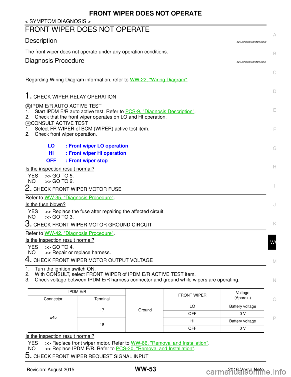
1. CHECK WIPER RELAY OPERATION
IPDM E/R AUTO ACTIVE TEST
1. Start IPDM E/R auto active test. Refer to PCS-9, "
Diagnosis Description".
2. Check that the front wiper operates on LO and HI operation.
CONSULT ACTIVE TEST
1. Select FR WIPER of BCM (WIPER) active test item.
2. Check front wiper operation.
Is the inspection result normal?
YES >> GO TO 5.
NO >> GO TO 2.
2. CHECK FRONT WIPER MOTOR FUSE
Refer to WW-35, "
Diagnosis Procedure".
Is the fuse blown?
YES >> Replace the fuse after repairing the affected circuit.
NO >> GO TO 3.
3. CHECK FRONT WIPER MOTOR GROUND CIRCUIT
Refer to WW-42, "
Diagnosis Procedure".
Is the inspection result normal?
YES >> GO TO 4.
NO >> Repair or replace harness.
4. CHECK FRONT WIPER MOTOR OUTPUT VOLTAGE
1. Turn the ignition switch ON.
2. With CONSULT, select FRONT WIPER of IPDM E/R ACTIVE TEST item.
3. Check voltage between IPDM E/R harness connector and ground while wipers are operating.
Is the inspection result normal?
YES >> Replace front wiper motor. Refer to WW-66, "Removal and Installation".
NO >> Replace IPDM E/R. Refer to PCS-30, "
Removal and Installation".
5. CHECK FRONT WIPER REQUEST SIGNAL INPUTLO : Front wiper LO operation
HI : Front wiper HI operation
OFF : Front wiper stop
IPDM E/R
GroundFRONT WIPER
Vo l ta g e
(Approx.)
Connector Terminal
E45 17
LO
Battery voltage
OFF 0 V
18 HI
Battery voltage
OFF 0 V
Revision: August 2015 2016 Versa Note
cardiagn.com
Page 3619 of 3641

WW-54
< SYMPTOM DIAGNOSIS >
FRONT WIPER DOES NOT OPERATE
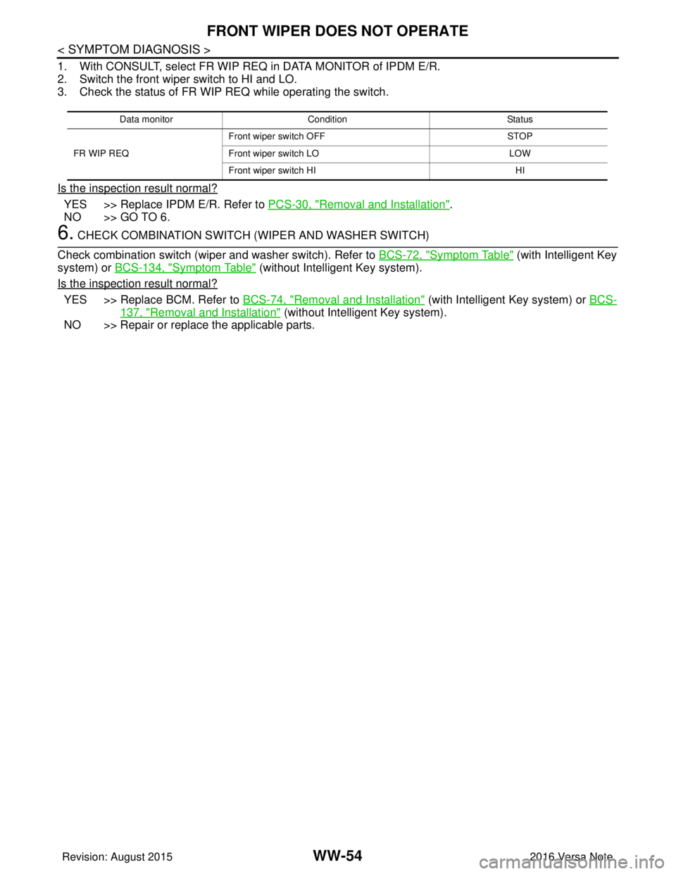
1. With CONSULT, select FR WIP REQ in DATA MONITOR of IPDM E/R.
2. Switch the front wiper switch to HI and LO.
3. Check the status of FR WIP REQ while operating the switch.
Is the inspection result normal?
YES >> Replace IPDM E/R. Refer to PCS-30, "Removal and Installation".
NO >> GO TO 6.
6. CHECK COMBINATION SWITCH (WIPER AND WASHER SWITCH)
Check combination switch (wiper and washer switch). Refer to BCS-72, "
Symptom Table" (with Intelligent Key
system) or BCS-134, "
Symptom Table" (without Intelligent Key system).
Is the inspection result normal?
YES >> Replace BCM. Refer to BCS-74, "Removal and Installation" (with Intelligent Key system) or BCS-
137, "Removal and Installation" (without Intelligent Key system).
NO >> Repair or replace the applicable parts.
Data monitor Condition Status
FR WIP REQ Front wiper switch OFF
STOP
Front wiper switch LO LOW
Front wiper switch HI HI
Revision: August 2015 2016 Versa Note
cardiagn.com