2016 NISSAN NOTE air condition
[x] Cancel search: air conditionPage 3536 of 3641

WCS
DIAGNOSIS SYSTEM (BCM) (WITH INTELLIGENT KEY SYSTEM)
WCS-21
< SYSTEM DESCRIPTION >
C
D E
F
G H
I
J
K L
M B A
O P
DIAGNOSIS SYSTEM (BCM) (WIT H INTELLIGENT KEY SYSTEM)
COMMON ITEM
COMMON ITEM : CONSULT Function (BCM - COMMON ITEM)INFOID:0000000012542986
APPLICATION ITEM
CONSULT performs the following functions via CAN communication with BCM.
SYSTEM APPLICATION
BCM can perform the following functions.
Direct Diagnostic Mode Description
ECU Identification The BCM part number is displayed.
Self Diagnostic Result The BCM self diagnostic results are displayed.
Data Monitor The BCM input/output data is displayed in real time.
Active Test The BCM activates outputs to test components.
Work support The settings for BCM functions can be changed.
Configuration • The vehicle specification can be read and saved.
• The vehicle specification can be written when replacing BCM.
CAN DIAG SUPPORT MNTR The result of transmit/receive diagnosis of CAN communication is displayed.
System Sub System Direct Diagnostic Mode
ECU Identification
Self Diagnostic Result
Data Monitor
Active Test
Work support
Configuration
CAN DIAG SUPPORT MNTR
Door lock
DOOR LOCK ×××
Rear window defogger REAR DEFOGGER ××
Warning chime BUZZER ××
Interior room lamp timer INT LAMP ×××
Exterior lamp HEAD LAMP ×××
Wiper and washer WIPER ×××
Turn signal and hazard warning lamps FLASHER ×××
Air conditioner AIR CONDITIONER ×
Intelligent Key system INTELLIGENT KEY ××××
Combination switch COMB SW ×
BCM BCM× × ×××
Immobilizer IMMU ××××
Interior room lamp battery saver BATTERY SAVER ×××
Vehicle security system THEFT ALM ××
RAP system RETAINED PWR ×
Signal buffer system SIGNAL BUFFER ×
TPMS AIR PRESSURE MONITOR ××××
Panic alarm system PANIC ALARM ×
Revision: August 2015 2016 Versa Note
cardiagn.com
Page 3538 of 3641

WCS
DIAGNOSIS SYSTEM (BCM) (WITHOUT INTELLIGENT KEY SYSTEM)WCS-23
< SYSTEM DESCRIPTION >
C
DE
F
G H
I
J
K L
M B A
O P
DIAGNOSIS SYSTEM (BCM) (WITHO UT INTELLIGENT KEY SYSTEM)
COMMON ITEM
COMMON ITEM : CONSULT Function (BCM - COMMON ITEM)INFOID:0000000012542988
APPLICATION ITEM
CONSULT performs the following functions via CAN communication with BCM.
SYSTEM APPLICATION
BCM can perform the following functions.
Direct Diagnostic Mode Description
ECU Identification The BCM part number is displayed.
Self Diagnostic Result The BCM self diagnostic results are displayed.
Data Monitor The BCM input/output data is displayed in real time.
Active Test The BCM activates outputs to test components.
Work support The settings for BCM functions can be changed.
Configuration • The vehicle specification can be read and saved.
• The vehicle specification can be written when replacing BCM.
CAN DIAG SUPPORT MNTR The result of transmit/receive diagnosis of CAN communication is displayed.
System Sub System Direct Diagnostic Mode
ECU Identification
Self Diagnostic Result
Data Monitor
Active Test
Work support
Configuration
CAN DIAG SUPPORT MNTR
Door lock
DOOR LOCK ×××
Rear window defogger REAR DEFOGGER ××
Warning chime BUZZER ××
Interior room lamp timer INT LAMP ×××
Remote keyless entry system MULTI REMOTE ENT ×××
Exterior lamp HEAD LAMP ×××
Wiper and washer WIPER ×××
Turn signal and hazard warning lamps FLASHER ××
Air conditioner AIR CONDITIONER ×
Combination switch COMB SW ×
BCM BCM× × ×××
Immobilizer IMMU ×××
Interior room lamp battery saver BATTERY SAVER ×××
Vehicle security system THEFT ALM ××
RAP system RETAINED PWR ××
Signal buffer system SIGNAL BUFFER ×
TPMS AIR PRESSURE MONITOR ××××
Panic alarm system PANIC ALARM ×
Revision: August 2015 2016 Versa Note
cardiagn.com
Page 3547 of 3641
WCS-32
< BASIC INSPECTION >
DIAGNOSIS AND REPAIR WORK FLOW
BASIC INSPECTION
DIAGNOSIS AND REPAIR WORK FLOW
Work FlowINFOID:0000000012432685
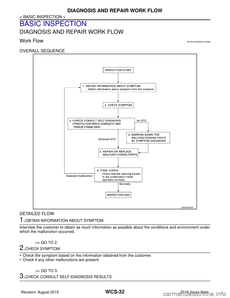
OVERALL SEQUENCE
DETAILED FLOW
1.OBTAIN INFORMATION ABOUT SYMPTOM
Interview the customer to obtain as much inform ation as possible about the conditions and environment under
which the malfunction occurred.
>> GO TO 2.
2.CHECK SYMPTOM
• Check the symptom based on the inform ation obtained from the customer.
• Check if any other malfunctions are present.
>> GO TO 3.
3.CHECK CONSULT SELF-DIAGNOSIS RESULTS
JSNIA4485GB
Revision: August 2015 2016 Versa Note
cardiagn.com
Page 3553 of 3641
WCS-38
< DTC/CIRCUIT DIAGNOSIS >
METER BUZZER CIRCUIT
METER BUZZER CIRCUIT
Component Function CheckINFOID:0000000012432690
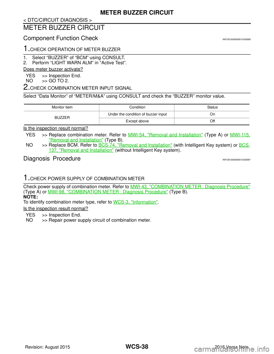
1.CHECK OPERATION OF METER BUZZER
1. Select “BUZZER” of “BCM” using CONSULT.
2. Perform “LIGHT WARN ALM” in “Active Test”.
Does meter buzzer activate?
YES >> Inspection End.
NO >> GO TO 2.
2.CHECK COMBINATION METER INPUT SIGNAL
Select “Data Monitor” of “METER/M&A” using CONSULT and check the “BUZZER” monitor value.
Is the inspection result normal?
YES >> Replace combination meter. Refer to MWI-54, "Removal and Installation" (Type A) or MWI-115,
"Removal and Installation" (Type B).
NO >> Replace BCM. Refer to BCS-74, "
Removal and Installation" (with Intelligent Key system) or BCS-
137, "Removal and Installation" (without Intelligent Key system).
Diagnosis ProcedureINFOID:0000000012432691
1.CHECK POWER SUPPLY OF COMBINATION METER
Check power supply of combination meter. Refer to MWI-43, "
COMBINATION METER : Diagnosis Procedure"
(Type A) or MWI-98, "COMBINATION METER : Diagnosis Procedure" (Type B).
NOTE:
To identify combination meter type, refer to WCS-3, "
Information".
Is the inspection result normal?
YES >> Inspection End.
NO >> Repair power supply circuit of combination meter.
Monitor item Condition Status
BUZZER Under the condition of buzzer input
On
Except above Off
Revision: August 2015 2016 Versa Note
cardiagn.com
Page 3555 of 3641
WCS-40
< DTC/CIRCUIT DIAGNOSIS >
SEAT BELT BUCKLE SWITCH SIGNAL CIRCUIT
YES >> GO TO 3.
NO >> Repair or replace harness or connector.
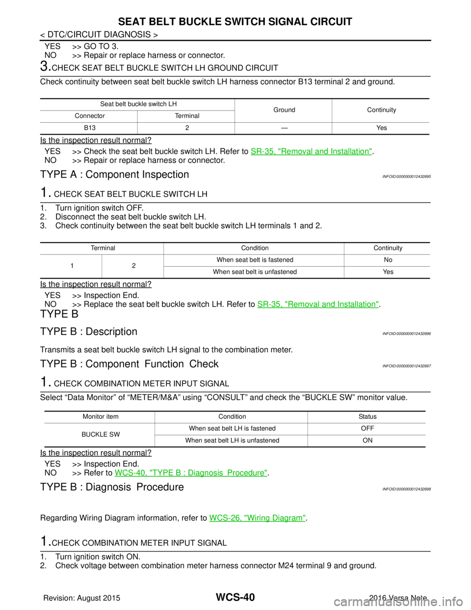
3.CHECK SEAT BELT BUCKLE SWITCH LH GROUND CIRCUIT
Check continuity between seat belt buckle swit ch LH harness connector B13 terminal 2 and ground.
Is the inspection result normal?
YES >> Check the seat belt buckle switch LH. Refer to SR-35, "Removal and Installation".
NO >> Repair or replace harness or connector.
TYPE A : Component InspectionINFOID:0000000012432695
1. CHECK SEAT BELT BUCKLE SWITCH LH
1. Turn ignition switch OFF.
2. Disconnect the seat belt buckle switch LH.
3. Check continuity between the seat belt buckle switch LH terminals 1 and 2.
Is the inspection result normal?
YES >> Inspection End.
NO >> Replace the seat belt buckle switch LH. Refer to SR-35, "
Removal and Installation".
TYPE B
TYPE B : DescriptionINFOID:0000000012432696
Transmits a seat belt buckle switch LH signal to the combination meter.
TYPE B : Component Function CheckINFOID:0000000012432697
1. CHECK COMBINATION METER INPUT SIGNAL
Select “Data Monitor” of “METER/M&A” using “C ONSULT” and check the “BUCKLE SW” monitor value.
Is the inspection result normal?
YES >> Inspection End.
NO >> Refer to WCS-40, "
TYPE B : DiagnosisProcedure".
TYPE B : Diagnosis ProcedureINFOID:0000000012432698
Regarding Wiring Diagram information, refer to WCS-26, "Wiring Diagram".
1.CHECK COMBINATION METER INPUT SIGNAL
1. Turn ignition switch ON.
2. Check voltage between combination meter harness connector M24 terminal 9 and ground.
Seat belt buckle switch LH GroundContinuity
Connector Terminal
B13 2—Yes
Terminal ConditionContinuity
12 When seat belt is fastened
No
When seat belt is unfastened Yes
Monitor itemCondition Status
BUCKLE SW When seat belt LH is fastened
OFF
When seat belt LH is unfastened ON
Revision: August 2015 2016 Versa Note
cardiagn.com
Page 3556 of 3641
WCS
SEAT BELT BUCKLE SWITCH SIGNAL CIRCUIT
WCS-41
< DTC/CIRCUIT DIAGNOSIS >
C
D E
F
G H
I
J
K L
M B A
O P
Is the inspection result normal?
YES >> Replace combination meter. Refer to MWI-115, "Removal and Installation" (Type B).
NO >> GO TO 2.
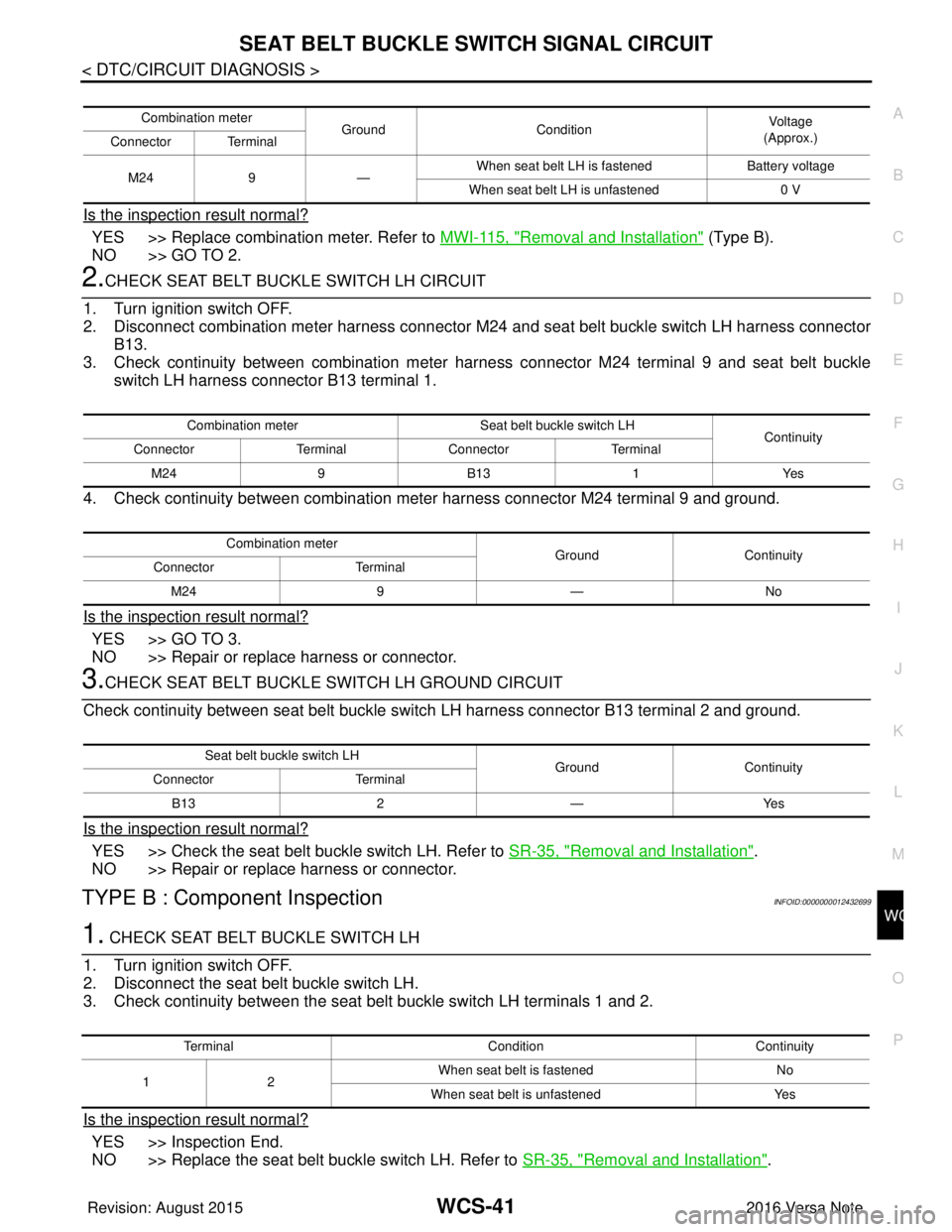
2.CHECK SEAT BELT BUCKLE SWITCH LH CIRCUIT
1. Turn ignition switch OFF.
2. Disconnect combination meter harness connector M24 and seat belt buckle switch LH harness connector
B13.
3. Check continuity between combination meter har ness connector M24 terminal 9 and seat belt buckle
switch LH harness connector B13 terminal 1.
4. Check continuity between combination meter harness connector M24 terminal 9 and ground.
Is the inspection result normal?
YES >> GO TO 3.
NO >> Repair or replace harness or connector.
3.CHECK SEAT BELT BUCKLE SWITCH LH GROUND CIRCUIT
Check continuity between seat belt buckle swit ch LH harness connector B13 terminal 2 and ground.
Is the inspection result normal?
YES >> Check the seat belt buckle switch LH. Refer to SR-35, "Removal and Installation".
NO >> Repair or replace harness or connector.
TYPE B : Component InspectionINFOID:0000000012432699
1. CHECK SEAT BELT BUCKLE SWITCH LH
1. Turn ignition switch OFF.
2. Disconnect the seat belt buckle switch LH.
3. Check continuity between the seat belt buckle switch LH terminals 1 and 2.
Is the inspection result normal?
YES >> Inspection End.
NO >> Replace the seat belt buckle switch LH. Refer to SR-35, "
Removal and Installation".
Combination meter
GroundCondition Vo l ta g e
(Approx.)
Connector Terminal
M24 9— When seat belt LH is fastened
Battery voltage
When seat belt LH is unfastened 0 V
Combination meterSeat belt buckle switch LH
Continuity
Connector TerminalConnector Terminal
M24 9B13 1Yes
Combination meter GroundContinuity
Connector Terminal
M24 9— No
Seat belt buckle switch LH
GroundContinuity
Connector Terminal
B13 2—Yes
Terminal ConditionContinuity
12 When seat belt is fastened
No
When seat belt is unfastened Yes
Revision: August 2015 2016 Versa Note
cardiagn.com
Page 3557 of 3641
WCS-42
< DTC/CIRCUIT DIAGNOSIS >
PARKING BRAKE SWITCH SIGNAL CIRCUIT
PARKING BRAKE SWITCH SIGNAL CIRCUIT
TYPE A
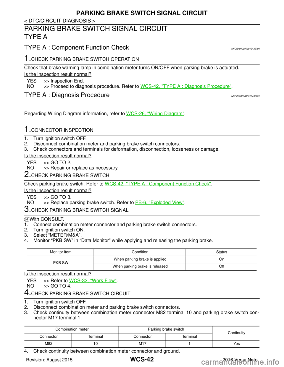
TYPE A : Component Function CheckINFOID:0000000012432700
1.CHECK PARKING BRAKE SWITCH OPERATION
Check that brake warning lamp in combination me ter turns ON/OFF when parking brake is actuated.
Is the inspection result normal?
YES >> Inspection End.
NO >> Proceed to diagnosis procedure. Refer to WCS-42, "
TYPE A : Diagnosis Procedure".
TYPE A : Diagnosis ProcedureINFOID:0000000012432701
Regarding Wiring Diagram information, refer to WCS-26, "Wiring Diagram".
1.CONNECTOR INSPECTION
1. Turn ignition switch OFF.
2. Disconnect combination meter and parking brake switch connectors.
3. Check connectors and terminals for deformation, disconnection, looseness or damage.
Is the inspection result normal?
YES >> GO TO 2.
NO >> Repair or replace as necessary.
2.CHECK PARKING BRAKE SWITCH
Check parking brake switch. Refer to WCS-42, "
TYPE A : Component Function Check".
Is the inspection result normal?
YES >> GO TO 3.
NO >> Replace parking brake switch. Refer to PB-6, "
Exploded View".
3.CHECK PARKING BRAKE SWITCH SIGNAL
With CONSULT.
1. Connect combination meter connector and parking brake switch connectors.
2. Turn ignition switch ON.
3. Select “METER/M&A”.
4. Monitor “PKB SW” in “Data Monitor” while applying and releasing the parking brake.
Is the inspection result normal?
YES >> Refer to WCS-32, "Work Flow".
NO >> GO TO 4.
4.CHECK PARKING BRAKE SWITCH CIRCUIT
1. Turn ignition switch OFF.
2. Disconnect combination meter and parking brake switch connectors.
3. Check continuity between combination meter connec tor M82 terminal 10 and parking brake switch con-
nector M17 terminal 1.
4. Check continuity between combination meter connector and ground.
Monitor item Condition Status
PKB SW When parking brake is applied
On
When parking brake is released Off
Combination meterParking brake switch
Continuity
Connector TerminalConnector Terminal
M82 10 M171Yes
Revision: August 2015 2016 Versa Note
cardiagn.com
Page 3558 of 3641
WCS
PARKING BRAKE SWITCH SIGNAL CIRCUITWCS-43
< DTC/CIRCUIT DIAGNOSIS >
C
DE
F
G H
I
J
K L
M B A
O P
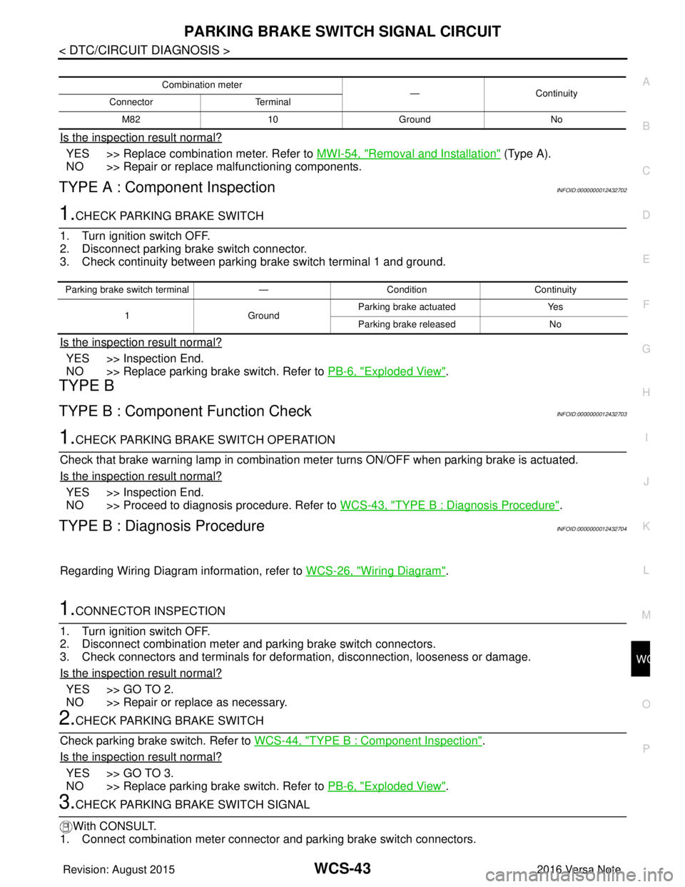
Is the inspection result normal?
YES >> Replace combination meter. Refer to MWI-54, "Removal and Installation" (Type A).
NO >> Repair or replace malfunctioning components.
TYPE A : Component InspectionINFOID:0000000012432702
1.CHECK PARKING BRAKE SWITCH
1. Turn ignition switch OFF.
2. Disconnect parking brake switch connector.
3. Check continuity between parking brake switch terminal 1 and ground.
Is the inspection result normal?
YES >> Inspection End.
NO >> Replace parking brake switch. Refer to PB-6, "
Exploded View".
TYPE B
TYPE B : Component Function CheckINFOID:0000000012432703
1.CHECK PARKING BRA KE SWITCH OPERATION
Check that brake warning lamp in combination meter turns ON/OFF when parking brake is actuated.
Is the inspection result normal?
YES >> Inspection End.
NO >> Proceed to diagnosis procedure. Refer to WCS-43, "
TYPE B : Diagnosis Procedure".
TYPE B : Diagnosis ProcedureINFOID:0000000012432704
Regarding Wiring Diagram information, refer to WCS-26, "Wiring Diagram".
1.CONNECTOR INSPECTION
1. Turn ignition switch OFF.
2. Disconnect combination meter and parking brake switch connectors.
3. Check connectors and terminals for deformation, disconnection, looseness or damage.
Is the inspection result normal?
YES >> GO TO 2.
NO >> Repair or replace as necessary.
2.CHECK PARKING BRAKE SWITCH
Check parking brake switch. Refer to WCS-44, "
TYPE B : Component Inspection".
Is the inspection result normal?
YES >> GO TO 3.
NO >> Replace parking brake switch. Refer to PB-6, "
Exploded View".
3.CHECK PARKING BRAKE SWITCH SIGNAL
With CONSULT.
1. Connect combination meter connector and parking brake switch connectors.
Combination meter —Continuity
Connector Terminal
M82 10 Ground No
Parking brake switch terminal —Condition Continuity
1 GroundParking brake actuated
Yes
Parking brake released No
Revision: August 2015 2016 Versa Note
cardiagn.com