2016 NISSAN NOTE key
[x] Cancel search: keyPage 2299 of 3641
![NISSAN NOTE 2016 Service Repair Manual LAN
BCM BRANCH LINE CIRCUITLAN-111
< DTC/CIRCUIT DIAGNOSIS > [CAN SYSTEM (TYPE 504)]
C
D
E
F
G H
I
J
K L
B A
O P
N
BCM BRANCH LINE CIRCUIT
Diagnosis ProcedureINFOID:0000000012785748
1.CHECK CONNECTOR
NISSAN NOTE 2016 Service Repair Manual LAN
BCM BRANCH LINE CIRCUITLAN-111
< DTC/CIRCUIT DIAGNOSIS > [CAN SYSTEM (TYPE 504)]
C
D
E
F
G H
I
J
K L
B A
O P
N
BCM BRANCH LINE CIRCUIT
Diagnosis ProcedureINFOID:0000000012785748
1.CHECK CONNECTOR](/manual-img/5/57363/w960_57363-2298.png)
LAN
BCM BRANCH LINE CIRCUITLAN-111
< DTC/CIRCUIT DIAGNOSIS > [CAN SYSTEM (TYPE 504)]
C
D
E
F
G H
I
J
K L
B A
O P
N
BCM BRANCH LINE CIRCUIT
Diagnosis ProcedureINFOID:0000000012785748
1.CHECK CONNECTOR
1. Turn the ignition switch OFF.
2. Disconnect the battery cabl e from the negative terminal.
3. Check the terminals and connectors of the BC M for damage, bend and loose connection (unit side and
connector side).
Is the inspection result normal?
YES >> GO TO 2.
NO >> Repair the terminal and connector.
2.CHECK HARNESS FOR OPEN CIRCUIT
1. Disconnect the connector of BCM.
2. Check the resistance between the BCM harness connector terminals.
- With intelligent key
- Without intelligent key
Is the measurement value within the specification?
YES >> GO TO 3.
NO >> Repair the BCM branch line.
3.CHECK POWER SUPPLY AND GROUND CIRCUIT
Check the power supply and the ground circuit of the BCM. Refer to the following.
• With Intelligent Key system: BCS-67, "
Diagnosis Procedure"
• Without Intelligent Key system: BCS-129, "Diagnosis Procedure"
Is the inspection result normal?
YES (Present error)>>Replace the BCM. Refer to the following.
• With Intelligent Key system: BCS-74, "
Removal and Installation"
• Without Intelligent Key system: BCS-137, "Removal and Installation"
YES (Past error)>>Error was detected in the BCM branch line.
NO >> Repair the power supply and the ground circuit.
BCM harness connector Resistance (Ω)
Connector No. Terminal No.
M97 39 40 Approx. 108 – 132
BCM harness connector Resistance (Ω)
Connector No. Terminal No.
M18 3940Approx. 108 – 132
Revision: August 2015 2016 Versa Note
cardiagn.com
Page 2313 of 3641
![NISSAN NOTE 2016 Service Repair Manual LAN
BCM BRANCH LINE CIRCUITLAN-125
< DTC/CIRCUIT DIAGNOSIS > [CAN SYSTEM (TYPE 505)]
C
D
E
F
G H
I
J
K L
B A
O P
N
BCM BRANCH LINE CIRCUIT
Diagnosis ProcedureINFOID:0000000012785733
1.CHECK CONNECTOR
NISSAN NOTE 2016 Service Repair Manual LAN
BCM BRANCH LINE CIRCUITLAN-125
< DTC/CIRCUIT DIAGNOSIS > [CAN SYSTEM (TYPE 505)]
C
D
E
F
G H
I
J
K L
B A
O P
N
BCM BRANCH LINE CIRCUIT
Diagnosis ProcedureINFOID:0000000012785733
1.CHECK CONNECTOR](/manual-img/5/57363/w960_57363-2312.png)
LAN
BCM BRANCH LINE CIRCUITLAN-125
< DTC/CIRCUIT DIAGNOSIS > [CAN SYSTEM (TYPE 505)]
C
D
E
F
G H
I
J
K L
B A
O P
N
BCM BRANCH LINE CIRCUIT
Diagnosis ProcedureINFOID:0000000012785733
1.CHECK CONNECTOR
1. Turn the ignition switch OFF.
2. Disconnect the battery cabl e from the negative terminal.
3. Check the terminals and connectors of the BC M for damage, bend and loose connection (unit side and
connector side).
Is the inspection result normal?
YES >> GO TO 2.
NO >> Repair the terminal and connector.
2.CHECK HARNESS FOR OPEN CIRCUIT
1. Disconnect the connector of BCM.
2. Check the resistance between the BCM harness connector terminals.
- With intelligent key
- Without intelligent key
Is the measurement value within the specification?
YES >> GO TO 3.
NO >> Repair the BCM branch line.
3.CHECK POWER SUPPLY AND GROUND CIRCUIT
Check the power supply and the ground circuit of the BCM. Refer to the following.
• With Intelligent Key system: BCS-67, "
Diagnosis Procedure"
• Without Intelligent Key system: BCS-129, "Diagnosis Procedure"
Is the inspection result normal?
YES (Present error)>>Replace the BCM. Refer to the following.
• With Intelligent Key system: BCS-74, "
Removal and Installation"
• Without Intelligent Key system: BCS-137, "Removal and Installation"
YES (Past error)>>Error was detected in the BCM branch line.
NO >> Repair the power supply and the ground circuit.
BCM harness connector Resistance (Ω)
Connector No. Terminal No.
M97 39 40 Approx. 108 – 132
BCM harness connector Resistance (Ω)
Connector No. Terminal No.
M18 3940Approx. 108 – 132
Revision: August 2015 2016 Versa Note
cardiagn.com
Page 2323 of 3641

MA-8
< PERIODIC MAINTENANCE >
PERIODIC MAINTENANCE
NOTE:
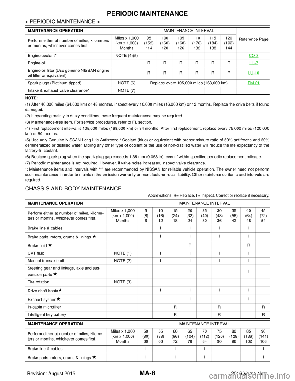
(1) After 40,000 miles (64,000 km) or 48 months, inspect every 10,000 miles (16,000 km) or 12 months. Replace the drive belts if found
damaged.
(2) If operating mainly in dusty conditions, more frequent maintenance may be required.
(3) Maintenance-free item. For service procedures, refer to FL section.
(4) First replacement interval is 105,000 miles (168,000 km) or 84 months. After first replacement, replace every 75,000 miles (120,000
km) or 60 months.
(5) Use only Genuine NISSAN Long Life Antifreeze / Coolant (blue) or equivalent with proper mixture ratio of 50% antifreeze and 50%
demineralized or distilled water. Mixing any other type of coolant or the use of non-distilled water will reduce the life expec tancy of the
factory-fill coolant.
(6) Replace spark plug when the spark plug gap exceeds 1.35 mm (0.053 in), even if within specified periodic replacement mileag e.
(7) Periodic maintenance is not required. However, if valve noise increases, inspect valve clearance.
*: Maintenance items and intervals with “*” are recommended by NISSAN for reli able vehicle operation. The owner need not perform
such maintenance in order to maintain the emission warranty or manufacturer recall liability. Other maintenance items and inter vals are
required.
CHASSIS AND BODY MAINTENANCE
Abbreviations: R= Replace. I = Inspec t. Correct or replace if necessary.
Engine coolant* NOTE (4)(5) CO-8
Engine oil RRRRRRLU-7
Engine oil filter (Use genuine NISSAN engine
oil filter or equivalent) RRRRRR
LU-10
Spark plugs (Platinum-tipped)NOTE (6) Replace every 105,000 miles (168,000 km) EM-21
Intake & exhaust valve clearance*NOTE (7)
MAINTENANCE OPERATION
MAINTENANCE INTERVAL
Reference Page
Perform either at number of miles, kilometers
or months, whichever comes first. Miles x 1,000
(km x 1,000)
Months 95
(152)
11 4 100
(160)
120 105
(168)
126 11 0
(176)
132 11 5
(184)
138 120
(192)
144
MAINTENANCE OPERATION MAINTENANCE INTERVAL
Perform either at number of miles, kilome-
ters or months, whichever comes first. Miles x 1,000
(km x 1,000)
Months 5
(8)
6 10
(16)
12 15
(24)
18 20
(32)
24 25
(40)
30 30
(48)
36 35
(56)
42 40
(64)
48 45
(72)
54
Brake line & cables IIII
Brake pads, rotors, drums & linings IIII
Brake fluid RR
CVT fluid NOTE (1)IIII
Manual transaxle oil NOTE (2)IIII
Steering gear and linkage, axle and sus-
pension parts II
Tire rotation NOTE (3)
Drive shaft boots IIII
Exhaust system II
In-cabin microfilter RRR
Intelligent key battery RRR
MAINTENANCE OPERATION MAINTENANCE INTERVAL
Perform either at number of miles, kilome-
ters or months, whichever comes first. Miles x 1,000
(km x 1,000) Months 50
(80) 60 55
(88) 66 60
(96) 72 65
(104) 78 70
(112) 84 75
(120) 90 80
(128) 96 85
(136) 102 90
(144) 108
Brake line & cables III II
Brake pads, rotors, drums & linings IIIII
Revision: August 2015
2016 Versa Note
cardiagn.com
Page 2324 of 3641

PERIODIC MAINTENANCEMA-9
< PERIODIC MAINTENANCE >
C
DE
F
G H
I
J
K L
M B
MA
N
O A
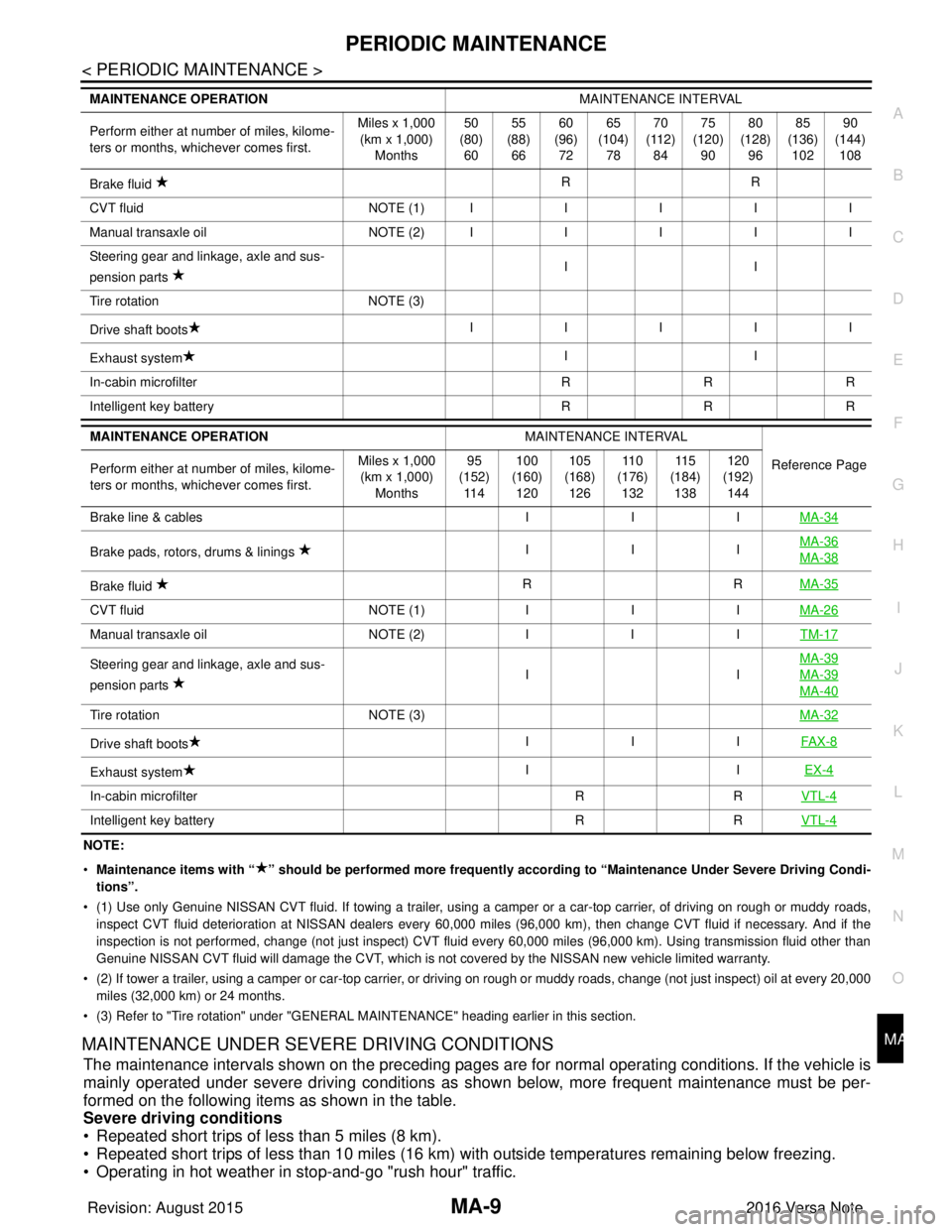
NOTE:
•
Maintenance items with “ ” shoul d be performed more frequently according to “Maintenance Under Severe Driving Condi-
tions”.
• (1) Use only Genuine NISSAN CVT fluid. If towing a trailer, using a camper or a car-top carrier, of driving on rough or muddy roads,
inspect CVT fluid deterioration at NISSAN dealers every 60,000 miles (96,000 km), then change CVT fluid if necessary. And if th e
inspection is not performed, change (not just inspect) CVT fluid every 60,000 miles (96,000 km). Using transmission fluid other than
Genuine NISSAN CVT fluid will damage the CVT, which is not covered by the NISSAN new vehicle limited warranty.
• (2) If tower a trailer, using a camper or car-top carrier, or driving on rough or muddy roads, change (not just inspect) oil a t every 20,000
miles (32,000 km) or 24 months.
• (3) Refer to "Tire rotation" under "GENERAL MAINTENANCE" heading earlier in this section.
MAINTENANCE UNDER SEVERE DRIVING CONDITIONS
The maintenance intervals shown on the preceding pages are for normal operating conditions. If the vehicle is
mainly operated under severe driving conditions as shown below, more frequent maintenance must be per-
formed on the following items as shown in the table.
Severe driving conditions
• Repeated short trips of less than 5 miles (8 km).
• Repeated short trips of less than 10 miles (16 km) wi th outside temperatures remaining below freezing.
• Operating in hot weather in stop-and-go "rush hour" traffic.
Brake fluid RR
C VT flu id NO TE (1)IIIII
M anu al t ra nsa xle o il NO TE (2)IIIII
Steering gear and linkage, axle and sus-
pension parts II
Tire rotation NOTE (3)
Drive shaft boots IIIII
Exhaust system II
In-cabin microfilter RRR
Intelligent key battery RRR
MAINTENANCE OPERATION MAINTENANCE INTERVAL
Reference Page
Perform either at number of miles, kilome-
ters or months, whichever comes first. Miles x 1,000
(km x 1,000) Months 95
(152) 11 4 100
(160) 120 105
(168) 126 11 0
(176) 132 11 5
(184) 138 120
(192) 144
Brake line & cables IIIMA-34
Brake pads, rotors, drums & linings IIIMA-36MA-38
Brake fluid
RR
MA-35
CVT fluid NOTE (1)IIIMA-26
Manual transaxle oil NOTE (2)IIITM-17
Steering gear and linkage, axle and sus-
pension parts IIMA-39MA-39
MA-40
Tire rotation
NOTE (3) MA-32
Drive shaft boots III
FAX-8
Exhaust system II
EX-4
In-cabin microfilter RRVTL-4
Intelligent key battery RRVTL-4
MAINTENANCE OPERATION MAINTENANCE INTERVAL
Perform either at number of miles, kilome-
ters or months, whichever comes first. Miles x 1,000
(km x 1,000)
Months 50
(80)
60 55
(88)
66 60
(96)
72 65
(104)
78 70
(112)
84 75
(120)
90 80
(128)
96 85
(136)
102 90
(144)
108
Revision: August 2015 2016 Versa Note
cardiagn.com
Page 2356 of 3641

CHASSIS AND BODY MAINTENANCEMA-41
< PERIODIC MAINTENANCE >
C
DE
F
G H
I
J
K L
M B
MA
N
O A
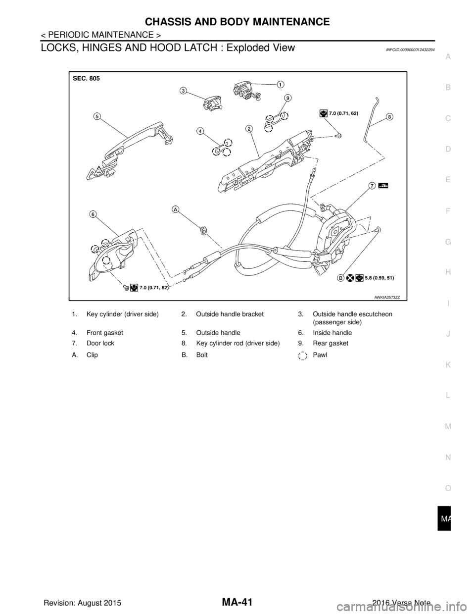
LOCKS, HINGES AND HOOD
LATCH : Exploded ViewINFOID:0000000012432294
1. Key cylinder (driver side) 2. Outside handle bracket 3. Outside handle escutcheon
(passenger side)
4. Front gasket 5. Outside handle 6. Inside handle
7. Door lock 8. Key cylinder rod (driver side) 9. Rear gasket
A. Clip B. Bolt Pawl
AWKIA2573ZZ
Revision: August 2015 2016 Versa Note
cardiagn.com
Page 2361 of 3641

MWI
MWI-3
C
DE
F
G H
I
J
K L
M B
A
O P
OIL PRESSURE WARNING
LAMP ...........................
65
OIL PRESSURE WARNING LAMP : System De-
scription ............................................................... ....
65
METER ILLUMINATION CONTROL ..................... ....65
METER ILLUMINATION CONTROL : System De-
scription ...................................................................
66
INFORMATION DISPLAY ..................................... ....66
INFORMATION DISPLAY : System Description .....66
OPERATION ................................................... ....68
Switch Name and Function ................................. ....68
DIAGNOSIS SYSTEM (COMBINATION
METER) ..............................................................
69
On Board Diagnosis Function ............................. ....69
CONSULT Function (METER/M&A) .......................71
ECU DIAGNOSIS INFORMATION ..............74
COMBINATION METER ................................. ....74
Reference Value ................................................. ....74
Fail-safe ..................................................................77
DTC Index ...............................................................77
BCM (BODY CONTROL MODULE) ...................78
List of ECU Reference ........................................ ....78
WIRING DIAGRAM ......................................79
METER SYSTEM ............................................ ....79
Wiring Diagram ................................................... ....79
BASIC INSPECTION ...................................92
DIAGNOSIS AND REPAIR WORK FLOW .... ....92
Work Flow ........................................................... ....92
DTC/CIRCUIT DIAGNOSIS .........................93
U1000 CAN COMM CI RCUIT .............................93
DTC Logic ........................................................... ....93
Diagnosis Procedure ..............................................93
U1010 CONTROL UNIT (CAN) ..........................94
Description ..............................................................94
DTC Logic ...............................................................94
Diagnosis Procedure ...............................................94
B2205 VEHICLE SPEED ....................................95
Description ..............................................................95
DTC Logic ...............................................................95
Diagnosis Procedure ..............................................95
B2267 ENGINE SPEED .....................................96
Description .......................................................... ....96
DTC Logic ...............................................................96
Diagnosis Procedure ...............................................96
B2268 WATER TEMP ........................................97
Description .......................................................... ....97
DTC Logic ...............................................................97
Diagnosis Procedure ........................................... ....97
POWER SUPPLY AND GROUND CIRCUIT ....98
COMBINATION METER ........................................ ....98
COMBINATION METER : Diagnosis Procedure .....98
BCM (BODY CONTROL SYSTEM) (WITHOUT IN-
TELLIGENT KEY SYSTEM) .................................. ....
98
BCM (BODY CONTROL SYSTEM) (WITHOUT
INTELLIGENT KEY SYSTEM) : Diagnosis Proce-
dure ..................................................................... ....
98
BCM (BODY CONTROL SYSTEM) (WITH INTEL-
LIGENT KEY SYSTEM) .............................................
99
BCM (BODY CONTROL SYSTEM) (WITH INTEL-
LIGENT KEY SYSTEM) : Diagnosis Procedure .. ....
99
FUEL LEVEL SENSOR SIGNAL CIRCUIT ....101
Description .............................................................101
Component Function Check ..................................101
Diagnosis Procedure ............................................101
Component Inspection ...........................................102
STEERING SWITCH .......................................103
Diagnosis Procedure .............................................103
AMBIENT SENSOR SIGNAL CIRCUIT ..........104
Description .............................................................104
Diagnosis Procedure ............................................104
Component Inspection ...........................................105
WASHER FLUID LEVEL SWITCH CIRCUIT ..106
Description .............................................................106
Diagnosis Procedure .............................................106
Component Inspection ...........................................106
SYMPTOM DIAGNOSIS ............................107
THE FUEL GAUGE INDICATOR DOES NOT
OPERATE .......................................................
107
Description ........................................................... ..107
Diagnosis Procedure .............................................107
THE OIL PRESSURE WARNING LAMP
DOES NOT TURN ON .....................................
108
Description .............................................................108
Diagnosis Procedure .............................................108
THE OIL PRESSURE WARNING LAMP
DOES NOT TURN OFF ...................................
109
Description .............................................................109
Diagnosis Procedure .............................................109
THE DOOR OPEN WARNING CONTINUES
DISPLAYING, OR DOES NOT DISPLAY .......
110
Description .............................................................110
Diagnosis Procedure .............................................110
THE PARKING BRAKE RELEASE WARNING
CONTINUES DISPLAYING, OR DOES NOT
DISPLAY .........................................................
111
Revision: August 2015 2016 Versa Note
cardiagn.com
Page 2417 of 3641
![NISSAN NOTE 2016 Service Repair Manual MWI
COMPONENT PARTSMWI-59
< SYSTEM DESCRIPTION > [TYPE B]
C
D
E
F
G H
I
J
K L
M B A
O P
METER SYSTEM : Combination MeterINFOID:0000000012432600
The combination meter controls the following items a cco NISSAN NOTE 2016 Service Repair Manual MWI
COMPONENT PARTSMWI-59
< SYSTEM DESCRIPTION > [TYPE B]
C
D
E
F
G H
I
J
K L
M B A
O P
METER SYSTEM : Combination MeterINFOID:0000000012432600
The combination meter controls the following items a cco](/manual-img/5/57363/w960_57363-2416.png)
MWI
COMPONENT PARTSMWI-59
< SYSTEM DESCRIPTION > [TYPE B]
C
D
E
F
G H
I
J
K L
M B A
O P
METER SYSTEM : Combination MeterINFOID:0000000012432600
The combination meter controls the following items a ccording to the signals received from each unit via CAN
communication and the signals from switches and sensors:
• Measuring instruments
• Indicator lamps
• Warning lamps
• Meter illumination control
• Information display
ARRANGEMENT OF COMBINATION METER
3. Washer fluid level switch Transmits the washer fluid level switch signal to the combination meter (for Cana-
da).
Refer to
WW-6, "
Component Parts Location" for detailed installation location.
4. Engine oil pressure sensor Transmits the engine oil pressure sensor signal to the ECM.
Refer to
EM-93, "
Exploded View" for detailed installation location.
5. Ambient sensor Transmits the ambient sensor signal to the combination meter.
6. TCM Transmits the shift position signal to the combination meter via CAN communica-
tion (with CVT).
Refer to
TM-61, "
CVT CONTROL SYSTEM : Component Parts Location" for de-
tailed installation location.
7. ECM Transmits the following signals to the combination meter via CAN communication:
• Engine speed signal
• Engine coolant temperature signal
• Fuel consumption monitor signal
• Engine oil pressure sensor signal
Refer to
EC-14, "
ENGINE CONTROL SYSTEM : ComponentPartsLocation" for
detailed installation location.
8. BCM Transmits the following signals to the combination meter via CAN communication:
• Door switch signal
• Buzzer signal
Refer to
BCS-6, "
BODY CONTROL SYSTEM : Component Parts Location" (with
Intelligent Key system) or BCS-77, "
BODY CONTROL SYSTEM : Component
Parts Location" (without Intelligent Key system) for detailed installation location.
9. Steering wheel audio control switches
(meter control switch) Transmits the meter control switch signal to the combination meter.
10. Combination meter Refer to MWI-59, "
METER SYSTEM : Combination Meter".
11 . Fuel level sensor unit and fuel pump (fuel
level sensor) Transmits the fuel level sensor signal to the combination meter.
No.
Component Function
AWNIA3630ZZ
Revision: August 2015 2016 Versa Note
cardiagn.com
Page 2421 of 3641
![NISSAN NOTE 2016 Service Repair Manual MWI
SYSTEMMWI-63
< SYSTEM DESCRIPTION > [TYPE B]
C
D
E
F
G H
I
J
K L
M B A
O P
SPEEDOMETER
SPEEDOMETER : System DescriptionINFOID:0000000012432603
SYSTEM DIAGRAM
DESCRIPTION
The ABS actuator and elect NISSAN NOTE 2016 Service Repair Manual MWI
SYSTEMMWI-63
< SYSTEM DESCRIPTION > [TYPE B]
C
D
E
F
G H
I
J
K L
M B A
O P
SPEEDOMETER
SPEEDOMETER : System DescriptionINFOID:0000000012432603
SYSTEM DIAGRAM
DESCRIPTION
The ABS actuator and elect](/manual-img/5/57363/w960_57363-2420.png)
MWI
SYSTEMMWI-63
< SYSTEM DESCRIPTION > [TYPE B]
C
D
E
F
G H
I
J
K L
M B A
O P
SPEEDOMETER
SPEEDOMETER : System DescriptionINFOID:0000000012432603
SYSTEM DIAGRAM
DESCRIPTION
The ABS actuator and electric unit (control unit) receives each wheel speed sensor signal and provides a vehi-
cle speed signal to the combination meter via CAN communication.
TACHOMETER
Information display Trip com-
puterCurrent fuel consump-
tion
• When reception time of an abnormal signal is 2 seconds or
less, the last received datum is used for calculation to indi-
cate the result.
• When reception time of an abnormal signal is more than two seconds, the last result calculated during normal condition is
indicated.
Average fuel consump-
tion
Distance to empty
Odo/trip meter An indicated value is maintained at communications blackout.
Buzzer The buzzer turns OFF by suspending communication.
Warning lamp/indicator lamp ABS warning lamp
The lamp turns ON by suspending communication.
Slip indicator lamp
Malfunction indicator lamp (MIL)
VDC OFF indicator lamp
EPS warning lamp
Brake warning lamp
High beam indicator lamp
The lamp turns OFF by suspending communication.
Turn signal indicator lamp
Door warning lamp
Light indicator lamp
Engine oil pressure warning lamp
High water temperature warning
lamp
Key warning lamp
O/D OFF indicator lamp
Shift P warning lamp
Engine start operation indicator lamp
Function
Specifications
AWNIA2379GB
Revision: August 2015 2016 Versa Note
cardiagn.com